


P5SD2-VM
Motherboard

E4207
Revised Edition V3
September 2008
Copyright © 2008 ASUSTeK Computer INC. All Rights Reserved.
No part of this manual, including the products and software described in it, may be reproduced, transmitted, transcribed, stored in a retrieval system, or translated into any language in any form or by any means, except documentation kept by the purchaser for backup purposes, without the express written permission of ASUSTeK Computer INC. (“ASUS”).
Product warranty or service will not be extended if: (1) the product is repaired, modified or altered, unless such repair, modification of alteration is authorized in writing byASUS; or (2) the serial number of the product is defaced or missing.
ASUS PROVIDES THIS MANUAL “AS IS” WITHOUT WARRANTY OF ANY KIND, EITHER EXPRESS OR IMPLIED, INCLUDING BUT NOT LIMITED TO THE IMPLIED WARRANTIES OR CONDITIONS OF MERCHANTABILITY OR FITNESS FOR A PARTICULAR PURPOSE. IN NO EVENT SHALL ASUS, ITS DIRECTORS, OFFICERS, EMPLOYEES OR AGENTS BE LIABLE FOR ANY INDIRECT, SPECIAL, INCIDENTAL, OR CONSEQUENTIAL DAMAGES (INCLUDING DAMAGES FOR LOSS OF PROFITS, LOSS OF BUSINESS, LOSS OF USE OR DATA, INTERRUPTION OF BUSINESS AND THE LIKE), EVEN IF ASUS HAS BEEN ADVISED OF THE POSSIBILITY OF SUCH DAMAGES ARISING FROM ANY DEFECT OR ERROR IN THIS MANUAL OR PRODUCT.
SPECIFICATIONS AND INFORMATION CONTAINED IN THIS MANUAL ARE FURNISHED FOR INFORMATIONAL USE ONLY, AND ARE SUBJECT TO CHANGE AT ANY TIME WITHOUT NOTICE, AND SHOULD NOT BE CONSTRUED AS A COMMITMENT BY ASUS. ASUS ASSUMES NO RESPONSIBILITY OR LIABILITY FOR ANY ERRORS OR INACCURACIES THAT MAY APPEAR IN THIS MANUAL, INCLUDING THE PRODUCTS AND SOFTWARE DESCRIBED IN IT.
Products and corporate names appearing in this manual may or may not be registered trademarks or copyrights of their respective companies, and are used only for identification or explanation and to the owners’ benefit, without intent to infringe.
ii

Contents
Notices......................................................................................................... |
vi |
Safety information...................................................................................... |
vii |
About this guide........................................................................................ |
viii |
P5SD2-VM specifications summary........................................................... |
x |
Chapter 1: |
Product introduction |
|
|
1.1 |
Welcome!....................................................................................... |
1-2 |
|
1.2 |
Package contents......................................................................... |
1-2 |
|
1.3 |
Special features............................................................................ |
1-2 |
|
|
1.3.1 |
Product highlights ............................................................ |
1-2 |
|
1.3.2 |
ASUS Special features .................................................... |
1-4 |
1.4 |
Before you proceed...................................................................... |
1-5 |
|
1.5 |
Motherboard overview................................................................. |
1-6 |
|
|
1.5.1 |
Placement direction ......................................................... |
1-6 |
|
1.5.2 |
Screw holes ..................................................................... |
1-6 |
|
1.5.3 |
Motherboard layout .......................................................... |
1-7 |
1.6 |
Central Processing Unit (CPU).................................................... |
1-8 |
|
|
1.6.1 |
Installing the CPU ............................................................ |
1-8 |
|
1.6.2 |
Installing the CPU heatsink and fan ............................... |
1-11 |
|
1.6.3 |
Uninstalling the CPU heatsink and fan .......................... |
1-12 |
1.7 |
System memory.......................................................................... |
1-13 |
|
|
1.7.1 |
Overview ........................................................................ |
1-13 |
|
1.7.2 |
Memory configurations . ................................................. |
1-13 |
|
1.7.3 |
Installing a DIMM ........................................................... |
1-18 |
|
1.7.4 |
Removing a DIMM ......................................................... |
1-18 |
1.8 |
Expansion slots.......................................................................... |
1-19 |
|
|
1.8.1 |
Installing an expansion card .......................................... |
1-19 |
|
1.8.2 |
Configuring an expansion card ...................................... |
1-19 |
|
1.8.3 |
Interrupt assignments .................................................... |
1-20 |
|
1.8.4 |
PCI slots . ....................................................................... |
1-21 |
|
1.8.5 |
PCI Express x1 slot . ...................................................... |
1-21 |
|
1.8.6 |
PCI Express x16 slot . .................................................... |
1-21 |
1.9 |
Jumpers |
....................................................................................... |
1-22 |
1.10 |
Connectors.................................................................................. |
1-24 |
|
|
1.10.1 .................................................. |
Rear panel connectors |
1-24 |
|
1.10.2 ........................................................ |
Internal connectors |
1-26 |
iii

Contents
Chapter 2: |
BIOS setup |
|
|
2.1 |
Managing and updating your BIOS............................................. |
2-2 |
|
|
2.1.1 |
Creating a bootable floppy disk....................................... |
2-2 |
|
2.1.2 |
ASUS EZ Flash utility...................................................... |
2-4 |
|
2.1.3 |
AFUDOS utility................................................................ |
2-5 |
|
2.1.4 |
ASUS CrashFree BIOS 2 utility....................................... |
2-7 |
|
2.1.5 |
ASUS Update utility......................................................... |
2-9 |
2.2 |
BIOS setup program................................................................... |
2-12 |
|
|
2.2.1 |
BIOS menu screen........................................................ |
2-13 |
|
2.2.2 |
Menu bar....................................................................... |
2-13 |
|
2.2.3 |
Navigation keys............................................................. |
2-13 |
|
2.2.4 |
Menu items.................................................................... |
2-14 |
|
2.2.5 |
Sub-menu items............................................................ |
2-14 |
|
2.2.6 |
Configuration fields........................................................ |
2-14 |
|
2.2.7 |
Pop-up window.............................................................. |
2-14 |
|
2.2.8 |
Scroll bar....................................................................... |
2-14 |
|
2.2.9 |
General help.................................................................. |
2-14 |
2.3 |
Main menu................................................................................... |
2-15 |
|
|
2.3.1 |
System Time.................................................................. |
2-15 |
|
2.3.2 |
System Date.................................................................. |
2-15 |
|
2.3.3 |
Legacy Diskette A ......................................................... |
2-15 |
|
2.3.4 |
Primary and SATAIDE Master/Slave................................... |
2-16 |
|
2.3.5 |
IDE Configuration.......................................................... |
2-17 |
|
2.3.6 |
System Information........................................................ |
2-18 |
2.4 |
Advanced menu.......................................................................... |
2-19 |
|
|
2.4.1 |
USB Configuration......................................................... |
2-19 |
|
2.4.2 |
CPU Configuration......................................................... |
2-20 |
|
2.4.3 |
Chipset ......................................................................... |
2-22 |
|
2.4.4 |
Onboard Devices Configuration.................................... |
2-24 |
|
2.4.5 |
PCI PnP......................................................................... |
2-25 |
2.5 |
Power menu................................................................................ |
2-26 |
|
|
2.5.1 |
Suspend Mode.............................................................. |
2-26 |
|
2.5.2 |
Repost Video on S3 Resume........................................ |
2-26 |
|
2.5.3 |
ACPI 2.0 Support........................................................... |
2-26 |
|
2.5.4 |
ACPI APIC Support....................................................... |
2-26 |
iv

Contents
|
2.5.5 |
APM Configuration ....................................................... |
2-27 |
|
2.5.6 |
Hardware Monitor.......................................................... |
2-28 |
2.6 |
Boot menu................................................................................... |
2-29 |
|
|
2.6.1 |
Boot Device Priority....................................................... |
2-29 |
|
2.6.2 |
Boot Settings Configuration........................................... |
2-30 |
|
2.6.3 |
Security.......................................................................... |
2-31 |
2.7 |
Exit menu..................................................................................... |
2-33 |
|
Chapter 3: |
Software support |
|
|
3.1 |
Installing an operating system.................................................... |
3-2 |
|
3.2 |
Support DVD information............................................................. |
3-2 |
|
|
3.2.1 |
Running the support DVD................................................ |
3-2 |
|
3.2.2 |
Drivers menu................................................................... |
3-3 |
|
3.2.3 |
Utilities menu................................................................... |
3-4 |
|
3.2.4 |
Make Disk menu.............................................................. |
3-5 |
|
3.2.5 |
Manual menu................................................................... |
3-6 |
|
3.2.6 |
ASUS Contact information............................................... |
3-6 |
Appendix |
CPU features |
|
|
A.1 |
Enhanced Intel SpeedStep® Technology (EIST)......................... |
A-2 |
|
|
A.1.1 |
System requirements....................................................... |
A-2 |
|
A.1.2 |
Using the EIST................................................................. |
A-2 |
A.2 |
Intel® Hyper-Threading Technology............................................ |
A-4 |
|
|
Using the Hyper-Threading Technology ........................................ |
A-4 |
|
Notices
Federal Communications Commission Statement
This device complies with Part 15 of the FCC Rules. Operation is subject to the following two conditions:
•This device may not cause harmful interference, and
•This device must accept any interference received including interference that may cause undesired operation.
This equipment has been tested and found to comply with the limits for a Class B digital device, pursuant to Part 15 of the FCC Rules. These limits are designed to provide reasonable protection against harmful interference in a residential installation. This equipment generates, uses and can radiate radio
frequency energy and, if not installed and used in accordance with manufacturer’s instructions, may cause harmful interference to radio communications. However, there is no guarantee that interference will not occur in a particular installation. If this equipment does cause harmful interference to radio or television reception, which can be determined by turning the equipment off and on, the user is encouraged to try to correct the interference by one or more of the following measures:
•Reorient or relocate the receiving antenna.
•Increase the separation between the equipment and receiver.
•Connect the equipment to an outlet on a circuit different from that to which the receiver is connected.
•Consult the dealer or an experienced radio/TV technician for help.
The use of shielded cables for connection of the monitor to the graphics card is required to assure compliance with FCC regulations. Changes or modifications to this unit not expressly approved by the party responsible for compliance could void the user’s authority to operate this equipment.
Canadian Department of Communications Statement
This digital apparatus does not exceed the Class B limits for radio noise emissions from digital apparatus set out in the Radio Interference Regulations of the Canadian Department of Communications.
This class B digital apparatus complies with Canadian ICES-003.
vi

Safety information
Electrical safety
•To prevent electrical shock hazard, disconnect the power cable from the electrical outlet before relocating the system.
•When adding or removing devices to or from the system, ensure that the power cables for the devices are unplugged before the signal cables are connected. If possible, disconnect all power cables from the existing system before you add a device.
•Before connecting or removing signal cables from the motherboard, ensure that all power cables are unplugged.
•Seek professional assistance before using an adpater or extension cord. These devices could interrupt the grounding circuit.
•Make sure that your power supply is set to the correct voltage in your area. If you are not sure about the voltage of the electrical outlet you are using, contact your local power company.
•If the power supply is broken, do not try to fix it by yourself. Contact a qualified service technician or your retailer.
Operation safety
•Before installing the motherboard and adding devices on it, carefully read all the manuals that came with the package.
•Before using the product, make sure all cables are correctly connected and the power cables are not damaged. If you detect any damage, contact your dealer immediately.
•To avoid short circuits, keep paper clips, screws, and staples away from connectors, slots, sockets and circuitry.
•Avoid dust, humidity, and temperature extremes. Do not place the product in any area where it may become wet.
•Place the product on a stable surface.
•If you encounter technical problems with the product, contact a qualified service technician or your retailer.
The symbol of the crossed out wheeled bin indicates that the product (electrical and electronic equipment, Mercury-containing button cell battery) should not be placed in municipal waste. Please check local regulations for disposal of electronic products.
vii

About this guide
This user guide contains the information you need when installing and configuring the motherboard.
How this guide is organized
This manual contains the following parts:
•Chapter 1: Product introduction
This chapter describes the features of the motherboard and the new technology it supports. It also lists the hardware setup procedures that you have to perform when installing system components. It includes description of the jumpers and connectors on the motherboard.
•Chapter 2: BIOS setup
This chapter tells how to change system settings through the BIOS Setup menus. Detailed descriptions of the BIOS parameters are also provided.
•Chapter 3: Software support
This chapter describes the contents of the support DVD that comes with the motherboard package.
•Appendix: CPU features
The appendix describes the CPU features this motherboard supports.
Where to find more information
Refer to the following sources for additional information and for product and software updates.
1.ASUS websites
The ASUS website provides updated information on ASUS hardware and software products. Refer to the ASUS contact information.
2.Optional documentation
Your product package may include optional documentation, such as warranty flyers, that may have been added by your dealer. These documents are not part of the standard package.
viii
Conventions used in this guide
To make sure that you perform certain tasks properly, take note of the following symbols used throughout this manual.
DANGER/WARNING: Information to prevent injury to yourself when trying to complete a task.
CAUTION: Information to prevent damage to the components when trying to complete a task.
IMPORTANT: Instructions that you MUST follow to complete a task.
NOTE: Tips and additional information to help you complete a task.
Typography
Bold text |
Indicates a menu or an item to select. |
Italics |
Used to emphasize a word or a phrase. |
<Key> |
Keys enclosed in the less-than and greater-than sign |
|
means that you must press the enclosed key. |
Example: <Enter> means that you must press the Enter or Return key.
<Key1>+<Key2>+<Key3> If you must press two or more keys simultaneously, the key names are linked with a plus sign (+).
Example: <Ctrl>+<Alt>+<D>
Command Means that you must type the command exactly as shown, then supply the required item or value enclosed in brackets.
Example: At the DOS prompt, type the command line:
afudos /i[filename]
afudos /iP5SD2VM.ROM
ix

P5SD2-VM specifications summary
|
CPU |
LGA775 socket for Intel® |
Core™2 Duo/ |
|
|
|
Pentium® D / Pentium® |
4 / Celeron® D Processors |
|
|
|
Support Intel® next generation 45nm CPU |
||
|
|
Compatible with Intel® 05B/05A/06 processors |
||
|
|
Intel® EIST Hyper-Threading Technology ready |
||
|
|
(Refer to www.asus.com for Intel CPU support list) |
||
|
Chipset |
Northbridge: SIS 672 |
|
|
|
|
Southbridge: SIS 968 |
|
|
|
System Bus |
1066 o.c / 800 / 533 MHz |
|
|
|
Memory |
2 x 240-pin DIMM sockets supports unbuffered non-ECC |
||
|
|
4GB667/533MHzDDR2 memory modules |
|
|
|
Expansion Slots |
1 x PCI Express x 16 slot |
||
|
|
1 x PCI Express x 1 slot |
|
|
|
|
2 x PCI slots |
|
|
|
VGA |
SIS Mirage 3+ Integrated Graphics, up to 256MB shared |
||
|
|
memory |
|
|
|
Storage |
Southbridge SIS968 supports: |
||
|
|
- 1 x UltraDMA 133/100/66/33 hard disk drives |
||
|
|
- 2 x SATA 3Gb/s with RAID 0, 1 function |
||
|
LAN |
PHY 10/100 LAN |
|
|
|
Audio |
Realtek® ALC 662 6-channel High DefinitionAudio |
||
|
|
CODEC |
|
|
|
|
Support Jack-detect and SPIDF-OUT interface |
||
|
USB |
8 x USB2.0 ports |
|
|
|
ASUS Features |
ASUS CrashFree BIOS 2 |
||
|
|
ASUS EZ Flash |
|
|
|
|
ASUS Q-Fan |
|
|
|
|
ASUS MyLogo |
|
|
|
Rear panel |
1 x PS/2 keyboard port |
|
|
|
|
1 x PS/2 mouse port |
|
|
|
|
1 x Parallel port |
|
|
1 x VGA port
1 x COM port
1 x LAN (RJ-45) port
4 x USB 2.0/1.1 ports
6-channel audio I/O port
(continued on the next page)
P5SD2-VM specifications summary
Internal connectors |
2 x USB 2.0 connectors support additional 4 USB 2.0 ports |
|
1 x CPU / 1 x Chassis fan connectors |
|
1 x S/PDIF Out connector |
|
1 x Chassis intrusion connector |
|
1 x Front panel audio connector |
|
1 x CD audio-in connector |
|
1 x 24-pin ATX power connector |
|
1 x 4-pin ATX 12 V power connector |
|
1 x 4-pin internal speaker connector |
|
1 x Floppy disk connector |
|
1 x System panel connector |
|
1 x IDE connector for two devices |
Support CD contents |
Drivers |
|
ASUS PC Probe 2 |
|
ASUS LiveUpdate Utility |
|
Anti-virus software (OEM version) |
Other Accessories |
1 x SATA cable |
|
1 x SATA power cable |
|
1 x UltraDMA 133/100/66 cable |
|
1 x FDD cable |
|
1 x I/O Shield |
|
User manual |
Form factor |
Micro-ATX form factor: 9.6’ in x 7.4’ in |
|
(24.4 cm x 18.8 cm) |
*Specifications are subject to change without notice.
xi

xii
This chapter describes the motherboard features and the new technologies
it supports.
Product1 introduction
ASUS P5SD2-VM |
1- |
1.1Welcome!
Thank you for buying an ASUS® P5SD2-VM motherboard!
The motherboard delivers a host of new features and latest technologies, making it another standout in the long line of ASUS quality motherboards!
Before you start installing the motherboard, and hardware devices on it, check the items in your package with the list below.
1.2Package contents
Check your motherboard package for the following items.
|
|
Motherboard |
ASUS P5SD2-VM |
Cables |
1 x Ultra DMA 133/100/66 cable |
|
1 x SATA cable |
|
1 x SATA power cable |
|
1 x Floppy disk drive cable |
Accessories |
I/O shield |
Application DVD |
ASUS motherboard support DVD |
Documentation |
User Manual |
If any of the above items is damaged or missing, contact your retailer.
1.3Special features
1.3.1Product highlights
Intel® Core™2 Processor Ready
This motherboard supports Intel® Core™2 processor in the LGA775 package. With Intel® Core™ microarchitecture technology and 1066 o.c / 800/ 533MHz FSB, Intel ® Core™2 processor is one of the most powerful and energy efficient CPU in the world.
Intel LGA775 CPU
This motherboard supports the latest Pentium 4 CPU from Intel in LGA775 package. With 1066 o.c/ 800/ 533MHz FSB, Hyper-Threading Technology and core-speeds up to 3.8GHz and beyond.
1- |
Chapter 1: Product introduction |
Intel® 65nm Dual-Core CPU support
This motherboard supports Intel® Pentium® D/Pentium® 4/Celeron® dualcore processors built on the 65-nanometer (nm) process technology with copper interconnect. Dual-core processors contain two physical CPU cores with dedicated L2 caches to meet demands for more powerful processing. Intel®’s 65nm process delivers breakthrough performance, enhanced media experience, and low power consumption. Intel® 65nm dual-core processors utilize the latest package technologies for a thinner, lighter design without compromising performance.
64-bit CPU support 
The motherboard supports 64-bit processors that provides high performance computing and faster memory access required for memory and data intensive applications.
Universal PCI-E Slot
The Universal PCI Express technology offers utilization flexibility of the Southbridge
PCI Express interface. It enables users to plug in an additional PCI Express graphics card to set up a dual graphics card platform on a single motherboard. ASUS’ own smart quick switch further detects how users installed their PCI
Express devices, and intelligently reroutes the PCI Express lanes for optimized bandwidth allocation.
Serial ATA 3Gb/s technology
This motherboard supports the next-generation hard drives based on the Serial ATA (SATA) 3Gb/s storage specification, delivering enhanced scalability and doubling the bus bandwidth for high-speed data retrieval and saves. Easily backup photos, videos and other entertainment contents to external devices. See page 1-31 for details.
S/PDIF digital sound ready
The motherboard supports the S/PDIF-out (SONY-PHILIPS Digtal Interface) function through the S/PDIF interface at mid-board. It allows to transfer digital audio without converting to analog format and keeps the best signal quality. See page 1-29 for details.
ASUS P5SD2-VM |
1- |

High Definition Audio 
Enjoy high-end sound quality on your PC! The onboard 6-channel HD audio (High
Definition Audio, previously codenamed Azalia) CODEC enables high-quality 192KHz/24-bit audio output, jack-sensing feature.
SIS Advanced HyperStreaming™ Architecture 
The motherboard supports the SIS HyperStreaming™ technology that smartly manages data streaming between the Northbridge and Southbridge, memory, graphics interface, and other peripherals for efficient and superior performance.
PCI Express™ interface 
The motherboard fully supports PCI Express, the latest I/O interconnect technology that speeds up the PCI bus. PCI Express features point topoint serial interconnections between devices and allows higher clockspeeds by carrying data in packets. This high speed interface is software compatible with existing PCI specifications.
1.3.2 ASUS Special features
ASUS Q-Fan technology 
The ASUS Q-Fan technology smartly adjusts the fan speeds according to the system loading to ensure quiet, cool, and efficient operation. See page 2 28 for details.
ASUS MyLogo™ 
This new feature present in the motherboard allows you to personalize and add style to your system with customizable boot logos.
ASUS EZ Flash
With the ASUS EZ Flash, you can easily update the system BIOS even before loading the operating system. No need to use a DOS-based utility or boot from a floppy disk. See page 2-4 for details.
ASUS CrashFree BIOS 2 
This feature allows you to restore the original BIOS data from the support CD in case when the BIOS codes and data are corrupted. This protection eliminates the need to buy a replacement ROM chip. See page 2-7 for details.
1- |
Chapter 1: Product introduction |

1.4Before you proceed
Take note of the following precautions before you install motherboard components or change any motherboard settings.
•Unplug the power cord from the wall socket before touching any component.
•Use a grounded wrist strap or touch a safely grounded object or a metal object, such as the power supply case, before handling components to avoid damaging them due to static electricity.
•Hold components by the edges to avoid touching the ICs on them.
•Whenever you uninstall any component, place it on a grounded antistatic pad or in the bag that came with the component.
•Before you install or remove any component, ensure
that the ATX power supply is switched off or the power cord is detached from the power supply. Failure to do so may cause severe damage to the motherboard, peripherals, and/or components.
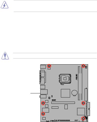
Onboard LED
The motherboard comes with a standby power LED that lights up to indicate that the system is ON, in sleep mode, or in soft-off mode. This is a reminder that you should shut down the system and unplug the power cable before removing or plugging in any motherboard component. The illustration below shows the location of the onboard LED.
P5SD2-VM |
SB_PWR
ON |
OFF |
Standby |
Powered |
Power |
Off |
P5SD2-VM Onboard LED
ASUS P5SD2-VM |
1- |
1.5Motherboard overview
Before you install the motherboard, study the configuration of your chassis to ensure that the motherboard fits into it.
Make sure to unplug the power cord before installing or removing the motherboard. Failure to do so can cause you physical injury and damage motherboard components.
1.5.1Placement direction
When installing the motherboard, make sure that you place it into the chassis in the correct orientation. The edge with external ports goes to the rear part of the chassis as indicated in the image below.
1.5.2Screw holes
Place six (6) screws into the holes indicated by circles to secure the motherboard to the chassis.
Do not overtighten the screws! Doing so can damage the motherboard.
Place this side towards the rear of the chassis
P5SD2-VM |
|
|
|
|
|
|
|
|
|
|
|
|
|
|
|
|
|
|
|
|
|
|
|
|
|
|
|
|
|
|
|
|
|
|
|
|
|
|
|
|
|
|
|
|
|
|
|
|
|
|
|
|
|
|
|
|
|
|
|
|
|
|
|
|
|
|
|
|
|
|
|
|
|
|
|
|
|
|
|
|
|
|
|
|
|
|
|
|
|
|
|
|
|
|
|
|
|
|
|
|
|
|
1- |
|
|
|
|
|
|
|
|
Chapter 1: Product introduction |
|||||||
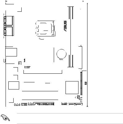
1.5.3Motherboard layout
18.38cm(7.24in)
PS/2KBMS
T: Mouse
B: Keyboard
ATX12V
COM1
|
|
PORT |
LGA775 |
|||
|
|
|||||
|
|
PARALLEL |
||||
|
|
|
|
|||
|
|
|
|
|||
|
|
|
|
|||
|
|
|
|
|
|
|
|
|
|
|
|
|
|
|
|
VGA1 |
|
|
|
|
|
|
|
|
|
|
|
|
|
USB34 |
|
|
|
|
|
|
|
|
|
|
|
LAN1_USB12
|
|
|
|
|
|
|
|
|
|
USB PWR |
|
|
|
|
|
|
|
|
||
AUDIO |
|
|
|
|
|
|
|
|
|
|
|
|
||||||||
CHA FAN |
|
|
PS2 |
|
|
|
|
|
|
|
|
|||||||||
|
|
|
|
|
|
|
|
|
|
|
|
|
|
|
|
|||||
|
|
|
|
|
|
|
|
|
|
USB78 |
|
|
|
|||||||
|
|
|
|
|
|
|
|
|
|
|
|
|
||||||||
|
|
|
|
|
|
|
|
|
|
|
|
|
|
|
||||||
|
|
|
|
|
|
|
|
|
|
|
|
|
|
|
|
|
|
|
|
|
|
|
|
|
Atheros |
|
|
|
|
|
|
|
|
|
|
|
|
|
|
||
|
|
|
|
|
|
|
|
|
|
|
|
|
|
|
|
|
|
|||
|
|
|
|
|
|
F2 |
|
|
|
|
|
|
|
|
|
|
|
PCIEX16 |
||
|
|
|
|
|
|
|
|
|
|
|
|
|
|
|
|
|
|
|||
|
|
|
|
|
|
|
|
|
|
|
|
|
|
|
|
|
|
|||
|
|
|
|
|
|
|
|
|
|
|
|
|
|
|
|
|
|
|||
|
|
|
|
4Mb |
|
|
|
|
|
|
|
|
|
|
|
|
660 |
|
||
|
|
|
|
BIOS |
|
|
|
|
|
|
|
|
|
|
|
|
- |
|
||
|
|
|
|
|
|
|
|
|
|
|
|
|
PCIEX1_1 |
|
RTM876 |
|
||||
|
|
|
|
|
|
|
|
|
|
|
|
|
|
|
|
|||||
|
|
|
|
|
|
|
|
|
|
|
|
|
|
|
|
|
|
|
|
|
|
|
|
|
|
|
|
|
|
|
|
|
P5SD2 |
|
|
||||||
|
|
Super I/O |
|
|
|
|
|
|
|
|
|
-VM |
||||||||
|
|
|
|
|
|
|
|
|
|
|
|
|
|
|
|
|
|
PCI1 |
||
|
|
|
|
|
|
|
|
|
|
|
|
|
|
|
|
|
|
|||
|
|
|
|
|
|
|
|
|
|
|
|
|
|
|
|
|
|
PCI2 |
||
|
|
ALC662 |
|
|
|
|
|
|
|
|
|
|
|
CHASSIS |
||||||
|
|
|
|
|
|
|
|
|
|
|
|
FLOPPY |
||||||||
|
|
|
|
|
|
CD |
|
AAFP |
|
|
SPDIF_OUT |
|||||||||
|
|
|
|
|
|
|
|
|
|
|
|
|
|
|
||||||
|
|
|
|
|
|
|
|
|
|
|
|
|
|
|||||||
|
|
|
|
|
|
|
|
|
|
|
|
|
|
|
|
|
|
|||
|
|
|
|
|
|
|
|
|
|
|
|
|
|
|
|
|
|
|
|
|
CPU_FAN
|
bit,240-pin module) |
bit,240-pin module) |
|
|
|
(64 |
(64 |
|
|
CR2032 3V |
DDR2DIMM1 |
DDR2DIMM2 |
EATXPWR |
24.4cm(9.6in) |
Lithium Cell
CMOS Power
SIS 968
|
|
|
|
SPEAKER |
|
PRI_IDE |
|
SB_PWR |
CLRTC |
|
PANELF |
||
USB56 |
SATA2 |
|
||||
|
|
SATA1 |
||||
|
|
|
|
|
|
|
|
|
|
|
|
|
|
Refer to section 1.10 Connectors for more information about rear panel connectors and internal connectors.
ASUS P5SD2-VM |
1- |
1.6Central Processing Unit (CPU)
The motherboard comes with a surface mount LGA775 socket designed for the Intel® Core™2 Duo/Pentium® D/Pentium® 4 and Celeron® processors.
•Make sure the AC power is off before you install the CPU.
• If installing a dual-core CPU, connect the chassis fan cable to the chassis fan connector to ensure system stability.
• Upon purchase of the motherboard, make sure that the PnP cap is on the socket and the socket contacts are not bent. Contact your retailer
immediately if the PnP cap is missing, or if you see any damage to the PnP cap/socket contacts/motherboard components. ASUS will shoulder the cost of repair only if the damage is shipment/transit-related.
•Keep the cap after installing the motherboard. ASUS will process Return
MerchandiseAuthorization (RMA) requests only if the motherboard comes with the cap on the LGA775 socket.
•The product warranty does not cover damage to the socket contacts resulting from incorrect CPU installation/removal, or misplacement/loss/ incorrect removal of the PnP cap.
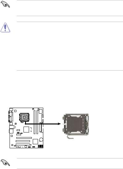
1.6.1Installing the CPU
To install a CPU:
1.Locate the CPU socket on the motherboard.
P5KPL-CM |
P5KPL-CM CPU Socket 775
Before installing the CPU, make sure that the cam box is facing towards you and the load lever is on your left.
1- |
Chapter 1: Product introduction |

2.Press the load lever with your thumb (A), then move it to the left
(B)until it is released from the retention tab.
To prevent damage to the socket pins, do not remove the PnP cap unless you are installing a CPU.
Retention tab
A
B
Load lever
3.Lift the load lever in the direction of the arrow to a 135º angle.
4.Lift the load plate with your thumb and forefinger to a 100º angle (4A), then push the PnP cap from the load plate window to remove (4B).
PnP cap Load plate
4B 
4A
3
5. |
Position the CPU over the socket, |
CPU notch |
|
making sure that the gold triangle |
|
|
is on the bottom left corner of the |
|
|
socket then fit the socket alignment |
|
|
key into the CPU notch. |
|
The CPU fits in only one correct orientation. DO NOT force the CPU into the socket to prevent bending the connectors on the socket and damaging the CPU!
Gold triangle mark
Alignment key
ASUS P5SD2-VM |
1- |
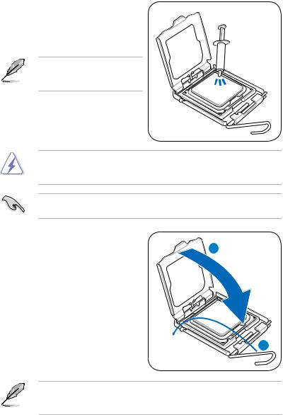
6.Apply several drops of thermal paste to the exposed area of the CPU that the heatsink will be in contact with, ensuring that it is spread in an even thin layer.
Some heatsinks come with preapplied thermal paste. If so, skip this step.
The Thermal Interface Material is toxic and inedible. If it gets into your eyes or touches your skin, ensure to wash it off immediately, and seek professional medical help.
To prevent contaminating the paste, DO NOT spread the paste with your finger directly.
7. |
Close the load plate (A), then push |
|
|
the load lever (B) until it snaps into |
A |
|
the retention tab. |
|
B
The motherboard supports Intel® LGA775 processors with the Intel® Enhanced Memory 64 Technology (EM64T), Enhanced Intel SpeedStep® Technology (EIST), and Hyper-Threading Technology.
1-10 |
Chapter 1: Product introduction |
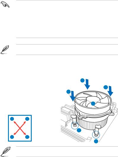
1.6.2Installing the CPU heatsink and fan
The Intel® LGA775 processor requires a specially designed heatsink and fan assembly to ensure optimum thermal condition and performance.
•When you buy a boxed Intel® processor, the package includes the CPU fan and heatsink assembly. If you buy a CPU separately, make sure that you use only Intel® certified multi directional heatsink and fan.
•Your Intel® LGA775 heatsink and fan assembly comes in a push-pin design and requires no tool to install.
•If you purchased a separate CPU heatsink and fan assembly, make sure that you have properly applied Thermal Interface Material to the CPU heatsink or CPU before you install the heatsink and fan assembly.
Make sure that you have installed the motherboard to the chassis before you install the CPU fan and heatsink assembly.
To install the CPU heatsink and fan
1.Place the heatsink on top of the installed CPU, making sure that the four fasteners match the holes on the motherboard.
2.Push down two fasteners at a time in a diagonal sequence to secure the heatsink and fan assembly in place.
AB
BA
A
B
B
A
1
1
Orient the heatsink and fan assembly such that the CPU fan cable is closest to the CPU fan connector.
ASUS P5SD2-VM |
1-11 |

3.Connect the CPU fan cable to the connector on the motherboard labeled CPU_FAN.
P5SD2-VM |
CPU_FAN
GND
CPU FAN PWR CPU FAN IN CPU FAN PWM
P5SD2-VM CPU Fan Connector
Do not forget to connect the CPU fan connector! Hardware monitoring errors can occur if you fail to plug this connector.
1.6.3Uninstalling the CPU heatsink and fan
To uninstall the CPU heatsink and fan |
A |
||
1. |
Disconnect the CPU fan cable from |
B |
|
|
the connector on the motherboard. |
B |
|
2. |
Rotate each fastener |
|
|
3. |
counterclockwise. |
A |
|
Pull up two fasteners at a time in a |
|
||
|
diagonal sequence to disengage the |
|
|
|
heatsink and fan assembly from the |
|
|
|
motherboard. |
|
|
|
A |
B |
|
BA
4.Carefully remove the heatsink and fan assembly from the motherboard.
1-12 |
Chapter 1: Product introduction |

1.7System memory
1.7.1Overview
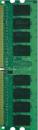
The motherboard comes with two Double Data Rate 2 (DDR2) Dual Inline Memory Modules (DIMM) sockets.
A DDR2 module has the same physical dimensions as a DDR DIMM but has a 240-pin footprint compared to the 184-pin DDR DIMM. DDR2 DIMMs are notched differently to prevent installation on a DDR DIMM socket.
The figure illustrates the location of the DDR2 DIMM sockets:
DIMM1 |
DIMM2 |
P5SD2-VM |
112 Pins 128 Pins
P5SD2-VM 240-pin DDR2 DIMM Sockets
1.7.2Memory configurations
You may install 512 MB, 1 GB and 2 GB unbuffered non ECC DDR2 DIMMs into the DIMM sockets.
•Always install DIMMs with the same CAS latency. For optimum compatibility, it is recommended that you obtain memory modules from the same vendor.
•When installing total memory of 4GB capacity or more, Windows 32-bit operation system may only recognize less than 3GB. Hence, a total installed memory of less than 3GB is recommended.
ASUS P5SD2-VM |
1-13 |
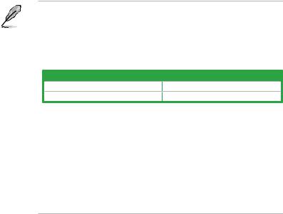
Notes on memory limitations
•Due to chipset limitation, this motherboard can only support up to
4 GB on the operating systems listed below. You may install a maximum of 2 GB DIMMs on each slot, but only DDR2-533 and DDR2-667 2 GB density modules are available for this configuration.
32-bit |
64-bit |
Windows® XP |
Windows® XP x 64 Edition |
Windows® 2003 Server |
Windows® 2003 Server x 64 Edition |
•Some old-version DDR2-667 DIMMs may not match Intel®’s On Die Termination (ODT) requirement and will automatically downgrade to run at DDR2-533. If this happens, contact your memory vendor to check the ODT value.
•Due to chipset limitation, DDR2-667 with CL=3 will be downgraded to run at DDR2-533 by default setting. If you want to operate with lower latency, adjust the memory timing manually. There will be 4MB reduction in total memory when enabling ASUS Thermostat function under Single Channel mode.
1-14 |
Chapter 1: Product introduction |

Qualified Vendors Lists (QVL)
DDR2 667
Size |
Vendor |
Model |
CL |
Brand |
SS/DS |
Component |
DIMM support |
|
|
|
|
|
|
|
|
A* |
B* |
256MB |
Kingston |
KVR667D2N5/256 |
N/A |
Elpida |
SS |
E2508AB-6E-E |
• |
• |
256MB |
Kingston |
KVR667D2N5/256 |
N/A |
Kingston |
SS |
D3216TLSAKL3U |
• |
• |
256MB |
Kingston |
KVR667D2N5/256 |
N/A |
Infineon |
SS |
HYB18T256800AF3SW65 33154 |
• |
• |
512MB |
Kingston |
KVR667D2N5/512 |
N/A |
Kingston |
SS |
D6408TE8WL-27 |
• |
• |
512MB |
Kingston |
KVR667D2N5/512 |
N/A |
Elpida |
SS |
E5108AGBG-6E-E |
• |
• |
1G |
Kingston |
KVR667D2N5/1G |
N/A |
Kingston |
DS |
D6408TE8WL-3 |
• |
• |
1G |
Kingston |
KVR667D2N5/1G |
N/A |
Kingston |
DS |
D6408TEBGGL3U |
• |
• |
1G |
Kingston |
KVR667D2N5/1G |
N/A |
Elpida |
DS |
E5108AGBG-6E-E |
• |
• |
512MB |
Samsung |
KR M378T6553CZ0-CE6 |
N/A |
Samsung |
SS |
K4T51083QC |
• |
• |
512MB |
Samsung |
KR M378T6453FZ0-CE6 |
N/A |
Samsung |
DS |
K4T56083QF-ZCE6 |
• |
• |
512MB |
Samsung |
M378T6553CZ3-CE6 |
N/A |
Samsung |
SS |
K4T51083QC-ZCE6 |
• |
• |
1G |
Samsung |
M378T2953CZ3-CE6 |
N/A |
Samsung |
DS |
K4T51083QC-ZCE6 |
• |
• |
1G |
Samsung |
KR M378T2953CZ0-CE6 |
N/A |
Samsung |
DS |
K4T51083QC-ZCE6 |
• |
• |
256MB |
Qimonda |
HYS64T32000HU-3S-A |
N/A |
Qimonda |
SS |
HYB18T512160AF-3SSSS17310 |
• |
• |
512MB |
Qimonda |
HYS64T32000HU-3S-A |
N/A |
Qimonda |
SS |
HYB18T5128000AF-3SSSS27416 |
• |
• |
512MB |
Qimonda |
HYS64T64000HU-3S-A |
N/A |
Qimonda |
SS |
HYB18T512800AF3SFSS05346 |
• |
• |
1G |
Qimonda |
HYS64T128020HU-3S-A |
N/A |
Qimonda |
DS |
HYB18T512800AF3SSSS28104 |
• |
• |
512MB |
Corsair |
VS512MB667D2 |
N/A |
Corsair |
SS |
64M8CFEGPS0900647 |
• |
• |
512MB |
Corsair |
VS512MB667D2 |
N/A |
Corsair |
DS |
MIII0052532M8CEC |
• |
• |
1G |
Corsair |
VS1GB667D2 |
N/A |
Corsair |
DS |
MID095D62864M8CEC |
• |
• |
1G |
Corsair |
XMS2-5400 |
4 |
Corsair |
DS |
Heat-Sink Package |
• |
• |
256MB |
HY |
HYMP532U64CP6-Y5 AB |
5 |
Hynix |
SS |
HY5PS121621CFP-Y5 |
• |
• |
512MB |
HY |
HYMP564U64AP8-Y4 AA |
N/A |
Hynix |
SS |
HY5PS12821AFP-Y4 |
• |
• |
512MB |
HY |
HYMP564U64AP8-Y5 AA |
N/A |
Hynix |
SS |
HY5PS12821AFP-Y5 |
• |
• |
1G |
HY |
HYMP512U64AP8-Y5 AB |
N/A |
Hynix |
DS |
HY5PS12821AFP-Y5 |
• |
• |
1G |
HY |
HYMP512U64CP8-Y5 AB |
5 |
Hynix |
DS |
HY5PS12521CFP-Y5 |
• |
• |
512MB |
Kingmax |
KLCC28F-A8EB5 |
N/A |
Elpida |
SS |
E5108AE-6E-E |
• |
• |
512MB |
Kingmax |
KLCC28F-A8KB5 |
N/A |
Kingmax |
SS |
KKEA88B4LAUG-29DX |
• |
• |
1G |
Kingmax |
KLCD48F-A8KB5 |
N/A |
Kingmax |
DS |
KKEA88B4LAUG-29DX |
• |
• |
512MB |
Apacer |
78.91092.420 |
N/A |
Elpida |
SS |
E5108AE-6E-E |
• |
• |
512MB |
Apacer |
AU512E667C5KBGC |
5 |
Apacer |
SS |
AM4B5708MIJS7E0627B |
• |
• |
512MB |
Apacer |
AU512E667C5KBGC |
5 |
Apacer |
SS |
AM4B5708GQJS7E06332F |
• |
• |
1G |
Apacer |
AU01GE667C5KBGC |
N/A |
Apacer |
DS |
AM4B5708GQJS7E0636B |
• |
• |
1G |
Apacer |
78.01092.420 |
5 |
Elpida |
DS |
E5108AE-6E-E |
• |
• |
1G |
Apacer |
AU01GE667C5KBGC |
5 |
Apacer |
DS |
AM4B5708MIJS7E0627B |
• |
• |
512MB |
ADATA |
M20EL5G3H3160B1C0Z |
N/A |
Elpida |
SS |
E5108AE-6E-E |
• |
• |
512MB |
ADATA |
M20AD5G3H3166I1C52 |
N/A |
ADATA |
SS |
AD29608A8A-3EG20648 |
• |
• |
512MB |
ADATA |
M20AD5G3H3166I1C52 |
N/A |
ADATA |
SS |
AD29608A8A-3EG20718 |
• |
• |
1G |
ADATA |
M2OAD5G3I4176I1C52 |
N/A |
ADATA |
DS |
AD29608A8A-3EG20645 |
• |
• |
2G |
ADATA |
M2OAD5H3J4170I1C53 |
N/A |
ADATA |
DS |
AD20908A8A-3EG 30724 |
• |
• |
512MB |
VDATA |
M2GVD5G3H31A4I1C52 |
N/A |
VDATA |
SS |
VD29608A8A-3EC20615 |
• |
• |
512MB |
VDATA |
M2YVD5G3H31P4I1C52 |
N/A |
VDATA |
SS |
VD29608A8A-3EG20627 |
• |
• |
512MB |
VDATA |
M2GVD5G3H166I1C52 |
N/A |
VDATA |
SS |
VD29608A8A-3EG20637 |
• |
• |
1G |
VDATA |
M2GVD5G3I41P6I1C52 |
N/A |
VDATA |
DS |
VD29608A8A-3EG20627 |
• |
• |
1G |
VDATA |
M2GVD5G3I41C4I1C52 |
N/A |
VDATA |
DS |
VD29608A8A-3EC20620 |
• |
• |
1G |
VDATA |
M2GVD5G3I4176I1C52 |
N/A |
VDATA |
DS |
VD29608A8A-3EG20641 |
• |
• |
512MB |
PSC |
AL6E8E63B-6E1K |
5 |
PSC |
SS |
A3R12E3GEF637BLC5N |
• |
• |
512MB |
PSC |
AL6E8E63J-6E1 |
5 |
PSC |
SS |
A3R12E3JFF717B9A00 |
• |
• |
1G |
PSC |
AL7E8E63B-6E1K |
5 |
PSC |
DS |
A3R12E3GEF637BLC5N |
• |
• |
1G |
PSC |
AL7E8E63J-6E1 |
5 |
PSC |
DS |
A3R12E3JFF717B9A01 |
• |
• |
256MB |
Nanya |
NT256T64UH4A1FY-3C |
N/A |
Nanya |
SS |
NT5TU32M16AG-3C |
• |
• |
512MB |
Nanya |
NT512T64U88A1BY-3C |
N/A |
Nanya |
SS |
NT5TU64M8AE-3C |
• |
• |
512MB |
MDT |
MDT 512MB |
4 |
MDT |
SS |
18D51280D-30648 |
• |
• |
1G |
MDT |
MDT 1024MB |
4 |
MDT |
DS |
18D51200D-30646 |
• |
• |
1G |
MDT |
MDT 1024MB |
4 |
MDT |
DS |
18D51280D-30646E |
• |
• |
(continued on the next page)
ASUS P5SD2-VM |
1-15 |
 Loading...