


P5KPL-C/1600
Motherboard

E3695
First Edition V1
February 2008
Copyright © 2008 ASUSTeK COMPUTER INC. All Rights Reserved.
No part of this manual, including the products and software described in it, may be reproduced, transmitted, transcribed, stored in a retrieval system, or translated into any language in any form or by any means, except documentation kept by the purchaser for backup purposes, without the express written permission of ASUSTeK COMPUTER INC. (“ASUS”).
Product warranty or service will not be extended if: (1) the product is repaired, modified or altered, unless such repair, modification of alteration is authorized in writing by ASUS; or (2) the serial number of the product is defaced or missing.
ASUS PROVIDES THIS MANUAL “AS IS” WITHOUT WARRANTY OF ANY KIND, EITHER EXPRESS OR IMPLIED, INCLUDING BUT NOT LIMITED TO THE IMPLIED WARRANTIES OR CONDITIONS OF MERCHANTABILITY OR FITNESS FOR A PARTICULAR PURPOSE. IN NO EVENT SHALL ASUS, ITS DIRECTORS, OFFICERS, EMPLOYEES OR AGENTS BE LIABLE FOR ANY INDIRECT, SPECIAL, INCIDENTAL, OR CONSEQUENTIAL DAMAGES (INCLUDING DAMAGES FOR LOSS OF PROFITS, LOSS OF BUSINESS, LOSS OF USE OR DATA, INTERRUPTION OF BUSINESS AND THE LIKE), EVEN IF ASUS HAS BEEN ADVISED OF THE POSSIBILITY OF SUCH DAMAGES ARISING FROM ANY DEFECT OR ERROR IN THIS MANUAL OR PRODUCT.
SPECIFICATIONS AND INFORMATION CONTAINED IN THIS MANUAL ARE FURNISHED FOR INFORMATIONAL USE ONLY, AND ARE SUBJECT TO CHANGE AT ANY TIME WITHOUT NOTICE, AND SHOULD NOT BE CONSTRUED AS A COMMITMENT BY ASUS. ASUS ASSUMES NO RESPONSIBILITY OR LIABILITY FOR ANY ERRORS OR INACCURACIES THAT MAY APPEAR IN THIS MANUAL, INCLUDING THE PRODUCTS AND SOFTWARE DESCRIBED IN IT.
Products and corporate names appearing in this manual may or may not be registered trademarks or copyrights of their respective companies, and are used only for identification or explanation and to the owners’ benefit, without intent to infringe.
ii

Contents
Notices......................................................................................................... |
vi |
Safety information...................................................................................... |
vii |
About this guide........................................................................................ |
viii |
P5KPL-C/1600 specifications summary..................................................... |
x |
Chapter 1: Product introduction
1.1 |
Welcome!....................................................................................... |
1-2 |
|
1.2 |
Package contents......................................................................... |
1-2 |
|
1.3 |
Special features............................................................................ |
1-3 |
|
|
1.3.1 |
Product highlights............................................................ |
1-3 |
|
1.3.2 |
Innovative ASUS features................................................ |
1-5 |
1.4 |
Before you proceed...................................................................... |
1-7 |
|
1.5 |
Motherboard overview................................................................. |
1-8 |
|
|
1.5.1 |
Placement direction......................................................... |
1-8 |
|
1.5.2 |
Screw holes..................................................................... |
1-8 |
|
1.5.3 |
Motherboard layout.......................................................... |
1-9 |
|
1.5.4 |
Layout contents............................................................. |
1-10 |
1.6 |
Central Processing Unit (CPU).................................................. |
1-11 |
|
|
1.6.1 |
Installing the CPU........................................................... |
1-11 |
|
1.6.2 |
Installing the CPU heatsink and fan.............................. |
1-14 |
|
1.6.3 |
Uninstalling the CPU heatsink and fan.......................... |
1-16 |
1.7 |
System memory.......................................................................... |
1-18 |
|
|
1.7.1 |
Overview........................................................................ |
1-18 |
|
1.7.2 |
Memory configurations.................................................. |
1-18 |
|
1.7.3 |
Installing a DIMM........................................................... |
1-23 |
|
1.7.4 |
Removing a DIMM......................................................... |
1-23 |
1.8 |
Expansion slots.......................................................................... |
1-24 |
|
|
1.8.1 |
Installing an expansion card.......................................... |
1-24 |
|
1.8.2 |
Configuring an expansion card...................................... |
1-24 |
|
1.8.3 |
Interrupt assignments.................................................... |
1-25 |
|
1.8.4 |
PCI slots........................................................................ |
1-26 |
|
1.8.5 |
PCI Express x16 slot..................................................... |
1-26 |
|
1.8.6 |
PCI Express x1 slot....................................................... |
1-26 |
1.9 |
Jumpers |
....................................................................................... |
1-27 |
iii

Contents
1.10 Connectors.................................................................................. |
1-29 |
|
1.10.1 |
Rear panel connectors.................................................. |
1-29 |
1.10.2 |
Internal connectors........................................................ |
1-31 |
Chapter 2: BIOS setup
2.1 |
Managing and updating your BIOS............................................. |
2-2 |
|
|
2.1.1 |
Creating a bootable floppy disk....................................... |
2-2 |
|
2.1.2 |
ASUS EZ Flash 2 utility................................................... |
2-4 |
|
2.1.3 |
AFUDOS utility................................................................ |
2-5 |
|
2.1.4 |
ASUS CrashFree BIOS 3 utility....................................... |
2-7 |
|
2.1.5 |
ASUS Update utility......................................................... |
2-9 |
2.2 |
BIOS setup program................................................................... |
2-12 |
|
|
2.2.1 |
BIOS menu screen........................................................ |
2-13 |
|
2.2.2 |
Menu bar....................................................................... |
2-13 |
|
2.2.3 |
Navigation keys............................................................. |
2-13 |
|
2.2.4 |
Menu items.................................................................... |
2-14 |
|
2.2.5 |
Sub-menu items............................................................ |
2-14 |
|
2.2.6 |
Configuration fields........................................................ |
2-14 |
|
2.2.7 |
Pop-up window.............................................................. |
2-14 |
|
2.2.8 |
Scroll bar....................................................................... |
2-14 |
|
2.2.9 |
General help.................................................................. |
2-14 |
2.3 |
Main menu................................................................................... |
2-15 |
|
|
2.3.1 |
System Time.................................................................. |
2-15 |
|
2.3.2 |
System Date.................................................................. |
2-15 |
|
2.3.3 |
Legacy Diskette A.......................................................... |
2-15 |
|
2.3.4 |
Primary IDE Master/Slave, SATA 1~4........................... |
2-16 |
|
2.3.5 |
IDE Configuration.......................................................... |
2-17 |
|
2.3.6 |
System Information........................................................ |
2-18 |
2.4 |
Advanced menu.......................................................................... |
2-19 |
|
|
2.4.1 |
JumperFree Configuration............................................. |
2-19 |
|
2.4.2 |
USB Configuration......................................................... |
2-22 |
|
2.4.3 |
CPU Configuration......................................................... |
2-23 |
|
2.4.4 |
Chipset.......................................................................... |
2-24 |
|
2.4.5 |
Onboard Devices Configuration.................................... |
2-26 |
|
2.4.6 |
PCI PnP......................................................................... |
2-27 |
iv

Contents
2.5 |
Power menu................................................................................ |
2-28 |
|
|
2.5.1 |
Suspend Mode.............................................................. |
2-28 |
|
2.5.2 |
ACPI 2.0 Support........................................................... |
2-29 |
|
2.5.3 |
ACPI APIC Support....................................................... |
2-29 |
|
2.5.4 |
APM Configuration........................................................ |
2-29 |
|
2.5.5 |
Hardware Monitor.......................................................... |
2-31 |
2.6 |
Boot menu................................................................................... |
2-32 |
|
|
2.6.1 |
Boot Device Priority....................................................... |
2-32 |
|
2.6.2 |
Boot Settings Configuration........................................... |
2-33 |
|
2.6.3 |
Security.......................................................................... |
2-34 |
2.7 |
Tools menu.................................................................................. |
2-36 |
|
|
ASUS EZ Flash 2......................................................................... |
2-36 |
|
2.8 |
Exit menu..................................................................................... |
2-37 |
|
Chapter 3: Software support
3.1 |
Installing an operating system.................................................... |
3-2 |
|
3.2 |
Support CD information............................................................... |
3-2 |
|
|
3.2.1 |
Running the support CD.................................................. |
3-2 |
|
3.2.2 |
Drivers menu................................................................... |
3-3 |
|
3.2.3 |
Utilities menu................................................................... |
3-4 |
|
3.2.4 |
ASUS Contact information............................................... |
3-5 |
Appendix: CPU features
A.1 |
Intel® EM64T.................................................................................. |
A-2 |
|
|
Using the Intel® EM64T feature...................................................... |
A-2 |
|
A.2 |
Enhanced Intel SpeedStep® Technology (EIST)......................... |
A-2 |
|
|
A.2.1 |
System requirements....................................................... |
A-2 |
|
A.2.2 |
Using the EIST................................................................. |
A-3 |
A.3 |
Intel® Hyper-Threading Technology............................................ |
A-4 |
|
|
Using the Hyper-Threading Technology ........................................ |
A-4 |
|

Notices
Federal Communications Commission Statement
This device complies with Part 15 of the FCC Rules. Operation is subject to the following two conditions:
•This device may not cause harmful interference, and
•This device must accept any interference received including interference that may cause undesired operation.
This equipment has been tested and found to comply with the limits for a Class B digital device, pursuant to Part 15 of the FCC Rules. These limits are designed to provide reasonable protection against harmful interference in a residential installation. This equipment generates, uses and can radiate radio
frequency energy and, if not installed and used in accordance with manufacturer’s instructions, may cause harmful interference to radio communications. However, there is no guarantee that interference will not occur in a particular installation. If this equipment does cause harmful interference to radio or television reception, which can be determined by turning the equipment off and on, the user is encouraged to try to correct the interference by one or more of the following measures:
•Reorient or relocate the receiving antenna.
•Increase the separation between the equipment and receiver.
•Connect the equipment to an outlet on a circuit different from that to which the receiver is connected.
•Consult the dealer or an experienced radio/TV technician for help.
The use of shielded cables for connection of the monitor to the graphics card is required to assure compliance with FCC regulations. Changes or modifications to this unit not expressly approved by the party responsible for compliance could void the user’s authority to operate this equipment.
Canadian Department of Communications Statement
This digital apparatus does not exceed the Class B limits for radio noise emissions from digital apparatus set out in the Radio Interference Regulations of the Canadian Department of Communications.
This class B digital apparatus complies with Canadian ICES-003.
vi

Safety information
Electrical safety
•To prevent electrical shock hazard, disconnect the power cable from the electrical outlet before relocating the system.
•When adding or removing devices to or from the system, ensure that the power cables for the devices are unplugged before the signal cables are connected. If possible, disconnect all power cables from the existing system before you add a device.
•Before connecting or removing signal cables from the motherboard, ensure that all power cables are unplugged.
•Seek professional assistance before using an adpater or extension cord. These devices could interrupt the grounding circuit.
•Make sure that your power supply is set to the correct voltage in your area. If you are not sure about the voltage of the electrical outlet you are using, contact your local power company.
•If the power supply is broken, do not try to fix it by yourself. Contact a qualified service technician or your retailer.
Operation safety
•Before installing the motherboard and adding devices on it, carefully read all the manuals that came with the package.
•Before using the product, make sure all cables are correctly connected and the power cables are not damaged. If you detect any damage, contact your dealer immediately.
•To avoid short circuits, keep paper clips, screws, and staples away from connectors, slots, sockets and circuitry.
•Avoid dust, humidity, and temperature extremes. Do not place the product in any area where it may become wet.
•Place the product on a stable surface.
•If you encounter technical problems with the product, contact a qualified service technician or your retailer.
This symbol of the crossed out wheeled bin indicates that the product (electrical and electronic equipment, Mercury-containing button cell battery) should not be placed in municipal waste. Check local regulations for disposal of electronic products.
vii

About this guide
This user guide contains the information you need when installing and configuring the motherboard.
How this guide is organized
This manual contains the following parts:
•Chapter 1: Product introduction
This chapter describes the features of the motherboard and the new technology it supports. It also lists the hardware setup procedures that you have to perform when installing system components. It includes description of the jumpers and connectors on the motherboard.
•Chapter 2: BIOS setup
This chapter tells how to change system settings through the BIOS Setup menus. Detailed descriptions of the BIOS parameters are also provided.
•Chapter 3: Software support
This chapter describes the contents of the support CD that comes with the motherboard package.
•Appendix: CPU features
This Appendix describes the CPU features that the motherboard supports.
Where to find more information
Refer to the following sources for additional information and for product and software updates.
1.ASUS websites
The ASUS website provides updated information on ASUS hardware and software products. Refer to the ASUS contact information.
2.Optional documentation
Your product package may include optional documentation, such as warranty flyers, that may have been added by your dealer. These documents are not part of the standard package.
viii
Conventions used in this guide
To make sure that you perform certain tasks properly, take note of the following symbols used throughout this manual.
DANGER/WARNING: Information to prevent injury to yourself when trying to complete a task.
CAUTION: Information to prevent damage to the components when trying to complete a task.
IMPORTANT: Instructions that you MUST follow to complete a task.
NOTE: Tips and additional information to help you complete a task.
Typography
Bold text |
Indicates a menu or an item to select. |
Italics |
Used to emphasize a word or a phrase. |
<Key> |
Keys enclosed in the less-than and |
|
greater-than sign means that you must |
|
press the enclosed key. |
|
Example: <Enter> means that you must |
|
press the Enter or Return key. |
<Key1>+<Key2>+<Key3> |
If you must press two or more keys |
|
simultaneously, the key names are linked |
|
with a plus sign (+). |
|
Example: <Ctrl>+<Alt>+<D> |
Command |
Means that you must type the command |
|
exactly as shown, then supply the |
|
required item or value enclosed in |
|
brackets. |
|
Example: At the DOS prompt, type |
|
the command line: |
|
afudos /i[filename] |
|
afudos /iP5KPLC16.ROM |
ix

P5KPL-C/1600 specifications summary
CPU
Chipset
Front Side Bus
Memory
Expansion Slots
Storage
LAN
Audio
USB
ASUS Overclocking
Features
ASUS Special Features
LGA775 socket for Intel® Core™2 Quad / Core™2 Extreme / Core™2 Duo / Pentium® Extreme / Pentium® D / Pentium® 4 / Celeron® 400 Sequence Processors
Intel® Hyper-Threading Technology ready Supports next generation 45nm multi-core CPU Supports Intel® E64MT Technology
Supports Enhanced Intel SpeedStep® Technology (EIST) (Refer to www.asus.com for Intel CPU support list)
Northbridge: Intel® G31
Southbridge: Intel® ICH7
1600 (O.C)* / 1333 / 1066 / 800 MHz
Dual channel memory architecture
2 x 240-pin DIMM sockets support unbuffered non-ECC
4GB 1066(O.C)* / 800 / 667MHz DDR2 memory modules
*Due to the chipsets limitation, the actual running frequency is limited by the FSB.
1 x PCI Express x16 slot
1 x PCI Express x1 slot
3 x PCI slots
Southbridge Intel® ICH7 supports:
-1 x UltraDMA 100 / 66 hard disk drive
-4 x SATA 150 / 300 ports
PCIe Gigabit LAN
VT1708B High Definition Audio 8-channel CODEC
Supports Jack-detect and Anti Pop Funtion Compatible with Vista Premium OS
Max. 8 x USB 2.0 / 1.1 ports (4 ports at mid-board, 4 ports at back panel)
Stepless Frequency Selection (SFS):
- FSB tuning from 133 MHz up to 500 MHz at 1MHz increment
ASUS C.P.R. (CPU Parameter Recall) CPU Lock free
CPU Multiplier
ASUS CrashFree BIOS 3
ASUS Q-Fan
ASUS EZ Flash 2
ASUS MyLogo 2
Regulator Protection
DRAM Burnt proof
(continued on the next page)
P5KPL-C/1600 specifications summary
Rear panel
Internal connectors
BIOS features
Manageability
Supported OS
Support CD
Accessories
Form factor
1 x PS/2 keyboard port
1 x PS/2 mouse port
1 x Parallel port
1 x COM port
1 x LAN (RJ-45) port
4 x USB 2.0 / 1.1 ports
8-channel Audio I/O ports
2 x USB 2.0 connectors supports additional 4 USB 2.0 ports
1 x Floppy disk drive connector
1 x IDE connector
4 x Serial ATA connectors
1 x CPU fan connector
1 x Chassis fan connector
1 x Power fan connector
1 x Chassis intrusion connector
1 x Front panel audio connector
1 x CD audio in connector
1 x Speaker connector
1 x SPDIF out connector
1 x 24-pin EATX 12V power connector
1 x 4-pin ATX 12V power connector System panel connector
8Mb Flash ROM, AMI BIOS, Special H / W write protection, PnP, DMI v2.0, WfM2.0, SMBIOS v2.5, ACPI v2.0a
WOL by PME (Power Management Event), WOR by PME
Windows Vista / XP / 2003 Server / 2000 Server / 2000
Drivers
ASUS PC Probe II
ASUS LiveUpdate utility
1 x Serial ATA cable
1 x Serial ATA power cable
1 x UltraDMA 100 / 66 cable
1 x Floppy disk drive cable
1 x I/O shield User manual
ATX form factor: 12 in x 7 in (30.5 cm x 17.8 cm)
*Specifications are subject to change without notice.
xi

xii
This chapter describes the motherboard features and the new technologies it supports.
Product1 introduction
1.1Welcome!
Thank you for buying an ASUS® P5KPL-C/1600 motherboard!
The motherboard delivers a host of new features and latest technologies, making it another standout in the long line of ASUS quality motherboards!
Before you start installing the motherboard, and hardware devices on it, check the items in your package with the list below.
1.2Package contents
Check your motherboard package for the following items.
Motherboard |
ASUS P5KPL-C/1600 motherboard |
Cables |
1 x FDD cable |
|
1 x SATA cable |
|
1 x SATA power cable |
|
1 x UltraDMA 100/66 cable |
Accessories |
1 x I/O shield |
Application CD |
ASUS motherboard support CD |
Documentation |
User guide |
If any of the above items is damaged or missing, contact your retailer.
1- |
Chapter 1: Product introduction |

1.3Special features
1.3.1Product highlights
LGA775 Intel® Quad-core Processor Ready 

This motherboard supports the latest Intel® Quad-core processor in the LGA775 package. With 1333/1066/800MHz FSB, the Intel® Quad-core processor delivers excellent multi-tasking and multi-media performance and provides gamers with great gaming experience. It is one of the most powerful CPUs in the world.
Intel® Core™2 Processor Ready 

This motherboard supports the latest Intel® Core™2 processor in the LGA775 package. With the new Intel® Core™ microarchitecture technology and
1333/1066/800MHz FSB, the Intel® Core™2 processor is designed to provide powerful and energy efficient performance.
FSB 1600 support (O.C.) 
ASUS’s exclusive overclocking design now unleashes the ultimate potential of the
Intel® Core™2 processor. With the new Intel 45nm micro-architecture technology and FSB 1600 (O.C.) / 1333 / 1066 / 800 MHz, this motherboard allows you to enjoy the latest technology supported by one of the most powerful and energy efficient CPUs in the world.
64-bit CPU support
64-bit computing, the next generation technology to replace current 32-bit architecture, delivers advanced system performance, faster memory access and increased productivity. This motherboard provides excellent compatibility and flexibility by supporting either 64-bit or 32-bit architecture.
ASUS P5KPL-C/1600 |
1- |
PCI Express™ interface
The motherboard fully supports PCI Express, the latest I/O interconnect technology that speeds up the PCI bus. PCI Express features point topoint serial interconnections between devices and allows higher clockspeeds by carrying data in packets. This high speed interface is software compatible with existing PCI specifications.
DDR2 memory support 


The motherboard supports DDR2 memory that features data transfer rates of
667/800/1066 (O.C.) MHz to meet the higher bandwidth requirements of the latest 3D graphics, multimedia, and Internet applications. The dual-channel DDR2 architecture doubles the bandwidth of your system memory to boost system performance, eliminating bottlenecks with peak bandwidths of up to 12.8 GB/s
(17.0 GB/s when overclocking 1066). Without restriction to the memory size across the two channels, the motherboard allows you to install DIMMs with different memory size and enjoy dual-channel feature at the same time. See page 1-18 for details.
8-channel high definition audio 
Enjoy high-quality sound system on your PC! The onboard 8-channel HD audio
(High Definition Audio, previously codenamed Azalia) CODEC enables high-quality 192KHz/24-bit audio output, jack-detect feature, which automatically detects and identifies what types of peripherals are plugged into the audio I/O jacks and notifies users of inappropriate connection, meaning there will be no more confusion of Line-in, Line-out and Mic jacks. See pages 1-29, 1-34 and 2-25 for details.
Serial ATA 3Gb/s technology 
This motherboard supports the next-generation hard drives based on the Serial
ATA (SATA) 3Gb/s storage specification, delivering enhanced scalability and doubling the bus bandwidth for high-speed data retrieval and saves. Easily backup photos, videos and other entertainment contents to external devices. See page 1 32 for details.
1- |
Chapter 1: Product introduction |
USB 2.0 technology 
USB 2.0 is the latest connectivity standard for next generation components and peripherals. Backwards compatible with current USB 1.1 peripherals, USB 2.0 delivers transfer speeds up to 40 times faster at 480Mb/s, for easy connectivity and ultra-fast data transfers.
Gigabit LAN solution 
The on-board LAN controller is a highly integrated Gigabit LAN controller. It is enhanced with an ACPI management function to provide efficient power management for advanced operating systems.
1.3.2Innovative ASUS features
ASUS CrashFree BIOS3 
The ASUS CrashFree BIOS 3 allows users to restore corrupted BIOS data from a
USB flash disk containing the BIOS file. See page 2-7 for details.
ASUS Q-Fan technology 
The ASUS Q-Fan technology smartly adjusts the fan speeds according to the system loading to ensure quiet, cool, and efficient operation. See page 2 31 for details.
Fanless design 
ASUS has devoted special efforts to address the thermal issues across the motherboard, and most notably the areas that reside the CPU, power, Northbridge and Southbridge. The heat sinks and strategic board layout were tailor made to dissipate heat in the most efficient manner. With the addition of Stack Cool 2, users can even overclock without a noisy, bulky fan.
ASUS P5KPL-C/1600 |
1- |

ASUS EZ Flash2 

EZ Flash 2 is a user-friendly BIOS update utility. Simply press the predefined hotkey to launch the utility and update the BIOS without entering the OS. Update your BIOS easily without preparing a bootable diskette or using an OS-based flash utility. See page 2-4 and 2-36 for details.
C.P.R. (CPU Parameter Recall) 
The C.P.R. feature of the motherboard BIOS allows automatic re-setting to the BIOS default settings in case the system hangs due to overclocking. When the system hangs due to overclocking, C.P.R. eliminates the need to open the system chassis and clear the RTC data. Simply shut down and reboot the system, and the BIOS automatically restores the CPU default setting for each parameter.
ASUS MyLogo2™ 


This feature allows you to convert your favorite photo into a 256-color boot logo for a more colorful and vivid image on your screen. See page 2-33 for details.
Green ASUS
This motherboard and its packaging comply with the European Union’s Restriction on the use of Hazardous Substances (RoHS). This is in line with the ASUS vision of creating environment-friendly and recyclable products/packaging to safeguard consumers’ health while minimizing the impact on the environment.
1- |
Chapter 1: Product introduction |
1.4Before you proceed
Take note of the following precautions before you install motherboard components or change any motherboard settings.
•Unplug the power cord from the wall socket before touching any
component.
•Use a grounded wrist strap or touch a safely grounded object or to a metal object, such as the power supply case, before handling components to avoid damaging them due to static electricity.
•Hold components by the edges to avoid touching the ICs on them.
•Whenever you uninstall any component, place it on a grounded antistatic pad or in the bag that came with the component.
•Before you install or remove any component, ensure
that the ATX power supply is switched off or the power cord is detached from the power supply. Failure to do so may cause severe damage to the motherboard, peripherals, and/or components.
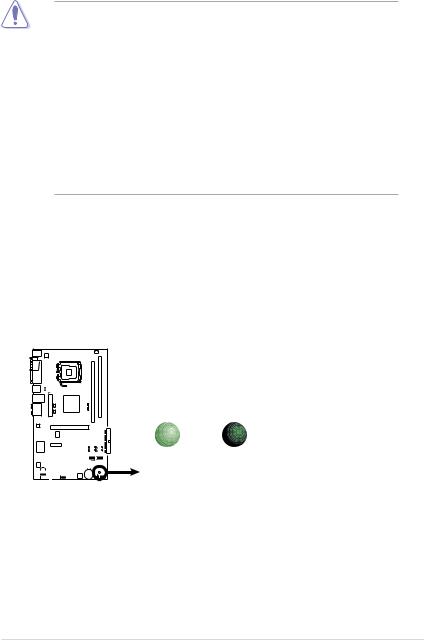
Onboard LED
The motherboard comes with a standby power LED. The green LED lights up to indicate that the system is ON, in sleep mode, or in soft-off mode. This is a
reminder that you should shut down the system and unplug the power cable before removing or plugging in any motherboard component. The illustration below shows the location of the onboard LED.
P5KPL-C/1600 |
SB_PWR
|
|
|
|
|
|
|
|
|
|
|
|
|
|
|
|
ON |
OFF |
|
|
|
|
|
|
|
|
|
|
|
|
|
|
|
|
||
|
|
|
|
|
|
|
|
|
|
|
|
|
|
|
|
||
|
|
|
|
|
|
|
|
|
|
|
|
|
|
|
|
||
|
|
|
|
|
|
|
|
|
|
|
|
|
|
|
|
||
|
|
|
|
|
|
|
|
|
|
|
|
|
|
|
|
||
|
|
|
|
|
|
|
|
|
|
|
|
|
|
|
|
Standby |
Powered |
|
|
|
|
|
|
|
|
|
|
|
|
|
|
|
|
||
|
|
|
|
|
|
|
|
|
|
|
|
|
|
|
|
Power |
Off |
|
|
|
|
|
|
|
|
|
|
|
|
|
|
|
|
P5KPL-C/1600 Onboard LED
ASUS P5KPL-C/1600 |
1- |
1.5Motherboard overview
Before you install the motherboard, study the configuration of your chassis to ensure that the motherboard fits into it.
Ensure to unplug the power cord before installing or removing the motherboard. Failure to do so can cause you physical injury and damage motherboard components.
1.5.1Placement direction
When installing the motherboard, make sure that you place it into the chassis in the correct orientation. The edge with external ports goes to the rear part of the chassis as indicated in the image below.
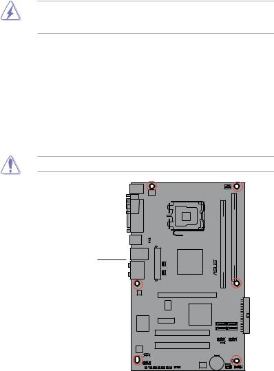
1.5.2Screw holes
Place six (6) screws into the holes indicated by circles to secure the motherboard to the chassis.
Do not overtighten the screws! Doing so can damage the motherboard.
Place this side towards the rear of the chassis
P5KPL-C/1600 |
Attansic |
L1 |
CD
|
|
|
|
|
|
|
|
|
|
|
|
|
|
|
|
|
|
|
|
|
|
|
|
|
|
|
|
|
|
|
|
|
|
|
|
|
|
|
|
|
|
|
|
|
|
|
|
|
|
|
|
|
|
|
|
|
|
|
|
|
|
|
|
|
|
|
|
|
|
|
|
1- |
|
|
|
Chapter 1: Product Introduction |
|||||||
1.5.3Motherboard layout
17.8cm (7.0in)
PS/2KBMS |
|
|
T:Mouse |
|
|
B:Keyboard |
|
|
|
|
ATX12V |
COM1 |
PORT |
LGA775 |
|
||
|
PARALLE |
|
USB34 4-USBPW1  _PS2
_PS2
LAN1_USB12
AUDIO
Atheros
AR8121
Super I/O
VIA
VT1708B
CD
AAFP 


|
|
|
|
|
|
|
|
|
|
|
|
|
EATXPWR |
|
CHAFANPWRFAN |
Intel |
|
|
|
|
|||||
|
G31 |
|
|
|
|
|||||||
|
|
|
|
|
|
|
|
|
|
|
||
|
|
|
|
|
|
|
|
|
|
|
|
|
|
|
|
|
|
|
|
PCIEX16 |
|
|
|
|
|
|
|
|
|
|
|
|
|
|
|
|
||
|
|
|
|
|
|
|
|
|
|
|
||
|
|
|
|
|
|
|
|
|
|
|
|
|
|
|
|
|
RTM870T-954 |
|
|
|
Intel |
||||
|
|
|
|
|
|
|||||||
|
|
|
|
|
|
|
|
|
||||
|
|
|
|
|
|
|
|
|
||||
|
|
|
|
|
|
|
|
ICH7 |
||||
|
PCIEX1_1 |
|
|
|
|
|
|
|
||||
|
|
|
|
|
|
|
|
|
|
|
|
|
|
|
|
|
|
|
|
|
|
|
|
|
|
|
|
|
|
|
|
|
PCI1 |
|
|
|
|
|
|
|
|
|
|
|
|
|
|
|
|
|
|
|
|
|
|
|
|
|
PCI2 |
|
|
|
|
|
|
|
|
|
|
|
|
|
|
|
|
|
|
|
|
|
|
|
|
|
PCI3 |
|
|
|
|
|
FLOPPY |
|
|
|
|
|
|
|
|
||||
|
|
|
|
|
|
8Mb |
|
|||||
|
|
|
|
|
|
|
SPDIF_OUT |
|
BIOS |
|
||
|
|
|
|
|
|
|
|
|
|
|
|
|
CPU_FAN
|
|
|
|
|
|
|
|
|
P5KPL-C/1600 DIMMA1 (64 bit,240-pin module) |
|
DDR2 DIMMB1 (64 bit,240-pin module) |
||
|
|
|
|
|||
|
|
|
DDR2 |
|
|
|
|
|
|
||||
30.5cm (12in)
PRI_IDE
SATA3 SATA4
SATA1 SATA2
USB56 USB78


 USBPW5-8
CR2032 3V |
SB_PWR |
Lithium Cell |
CLRTC SPEAKER |
CMOS Power |
|
|
CHASSIS F_PANEL |
Refer to section 1.10 Connectors for more information about rear panel connectors and internal connectors.
ASUS P5KPL-C/1600 |
1- |

1.5.4Layout contents
Slots |
|
Page |
|
1. |
DDR2 DIMM slots |
1-18 |
|
2. |
PCI slots |
1-26 |
|
3. |
PCI Express x 1 slot |
1-26 |
|
4. |
PCI Express x 16 slot |
1-26 |
|
|
|
|
|
Jumpers |
|
Page |
|
1. |
Clear RTC RAM (3-pin CLRTC) |
1-27 |
|
2. |
USB device wake-up (3-pin USBPW) |
1-28 |
|
|
|
|
|
Rear panel connectors |
Page |
|
|
1. |
PS/2 mouse port (green) |
1-29 |
|
2. |
Parallel port |
1-29 |
|
3. |
LAN (RJ-45) port |
1-29 |
|
4. |
Rear speaker out port (black) |
1-29 |
|
5. |
Center/Subwoofer port (orange) |
1-29 |
|
6. |
Line in port (light blue) |
1-29 |
|
7. |
Line out port (lime) |
1-29 |
|
8. |
Microphone port (pink) |
1-29 |
|
9. |
Side speaker out port (gray) |
1-30 |
|
10. |
USB 2.0 ports 1 and 2 |
1-30 |
|
11. |
USB 2.0 ports 3 and 4 |
1-30 |
|
12. |
Serial port |
1-30 |
|
13. |
PS/2 keyboard port (purple) |
1-30 |
|
|
|
|
|
Internal connectors |
Page |
|
|
1. |
Floppy disk drive connector (34-1 pin FLOPPY) |
1-31 |
|
2. |
Optical drive audio in connector (4-pin CD) |
1-31 |
|
3. |
IDE connector (40-1 pin PRI_IDE) |
1-32 |
|
4. |
Serial ATA connectors (7-pin SATA1, SATA2, SATA3, SATA4) |
1-32 |
|
5. |
Digital audio connector (4-1 pin SPDIF_OUT) |
1-33 |
|
6. |
Front panel audio connector (10-1 pin AAFP) |
1-34 |
|
7. |
USB connectors (10-1pin USB56, USB78) |
1-34 |
|
8. |
CPU, chassis, and power fan connectors (4-pin CPU_FAN, 3-pin |
|
|
|
CHA_FAN, and 3-pin PWR_FAN) |
1-35 |
|
9. |
ATX power connectors (24-pin EATXPWR, 4-pin ATX 12V) |
1-36 |
|
10. |
Chassis intrusion connector (4-1 pin CHASSIS) |
1-37 |
|
11. |
Speaker connector (4-1 pin SPEAKER) |
1-37 |
|
12. |
System panel connector (10-1 pin F_PANEL) |
1-38 |
|
1-10 |
Chapter 1: Product Introduction |
1.6Central Processing Unit (CPU)
The motherboard comes with a surface mount LGA775 socket designed for the Intel® Prescott / Smithfield / Cedarmill / Conroe / Conroe L / Presler / Kentsfield / Yorkfield processor in the 775-land package
•Upon purchase of the motherboard, make sure that the PnP cap is on
the socket and the socket contacts are not bent. Contact your retailer immediately if the PnP cap is missing, or if you see any damage to the PnP cap/socket contacts/motherboard components. ASUS will shoulder the cost of repair only if the damage is shipment/transit-related.
•Keep the cap after installing the motherboard. ASUS will process Return
Merchandise Authorization (RMA) requests only if the motherboard comes with the cap on the LGA775 socket.
•The product warranty does not cover damage to the socket contacts resulting from incorrect CPU installation/removal, or misplacement/loss/ incorrect removal of the PnP cap.
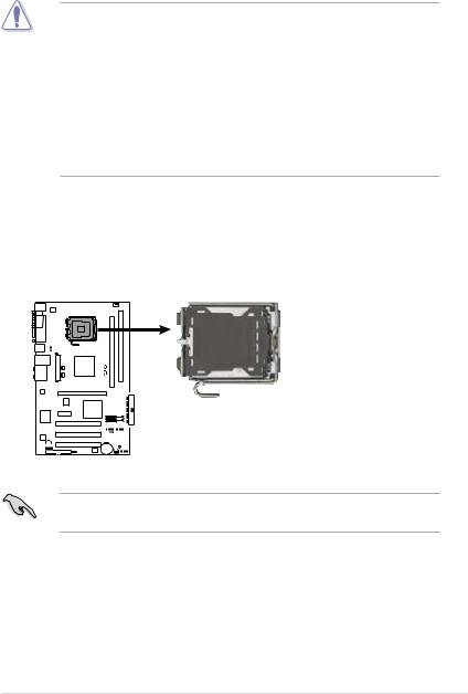
1.6.1Installing the CPU
To install a CPU:
1.Locate the CPU socket on the motherboard.
P5KPL-C/1600 |
P5KPL-C/1600 CPU Socket 775
Before installing the CPU, make sure that the cam box is facing towards you and the load lever is on your left.
ASUS P5KPL-C/1600 |
1-11 |

2.Press the load lever with your thumb (A), then move it to the left (B) until it is released from the retention tab.
Retention tab
A
Load lever
B |
|
|
|
PnP cap |
|
|
|
|
|||
|
|
|
|
||
This side of |
|
the socket |
|||
|
|||||
|
box should face you. |
||||
To prevent damage to the socket pins, do not remove the PnP cap unless you are installing a CPU.
3. |
Lift the load lever in the direction of |
|
|
the arrow to a 135º angle. |
|
4. |
Lift the load plate with your thumb |
|
|
and forefinger to a 100º angle (A), |
B |
|
then push the PnP cap from the load |
plate window to remove (B).
Load plate
1-12 |
Chapter 1: Product Introduction |

5.Position the CPU over the socket, making sure that the gold triangle is on the bottom-left corner of the socket. The socket alignment key should fit into the CPU notch.
Alignment key
CPU notch
Gold triangle mark 
The CPU fits in only one correct orientation. DO NOT force the CPU into the socket to prevent bending the connectors on the socket and damaging the CPU!
6.Close the load plate (A), then push the load lever (B) until it snaps into the retention tab.
7. If installing a dual-core CPU, |
B |
|
connect the chassis fan cable to the chassis fan connector to ensure system stability.
The motherboard supports Intel® LGA775 processors with the Intel® Enhanced Intel SpeedStep® Technology (EIST) and Hyper-Threading Technology. Refer to the Appendix for more information on these CPU features.
ASUS P5KPL-C/1600 |
1-13 |
1.6.2Installing the CPU heatsink and fan
The Intel® Prescott / Smithfield / Cedarmill / Conroe / Conroe L / Presler / Kentsfield / Yorkfield LGA775 processor requires a specially designed heatsink and fan assembly to ensure optimum thermal condition and performance.
• When you buy a boxed Intel® Prescott / Smithfield / Cedarmill / Conroe / Conroe L / Presler /Kentsfield / Yorkfield processor, the package
includes the CPU fan and heatsink assembly. If you buy a CPU separately, make sure that you use only Intel® certified multi directional heatsink and fan.
•Your Intel® Prescott / Smithfield / Cedarmill / Conroe / Conroe L / Presler / Kentsfield / Yorkfield LGA775 heatsink and fan assembly comes in a pushpin design and requires no tool to install.
•If you purchased a separate CPU heatsink and fan assembly, make sure that you have properly applied Thermal Interface Material to the CPU heatsink or CPU before you install the heatsink and fan assembly.
Make sure that you have installed the motherboard to the chassis before you install the CPU fan and heatsink assembly.
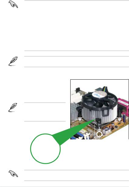
To install the CPU heatsink and fan:
1.Place the heatsink on top of the installed CPU, making sure that the four fasteners match the holes on the motherboard.
Orient the heatsink and fan assembly such that the CPU fan cable is closest to the CPU fan connector.
|
|
|
|
|
|
|
|
|
Motherboard hole |
||
Narrow end |
Fastener |
||||
|
|
|
|
|
|
of the groove |
|
|
|
||
Ensure to orient each fastener with the narrow end of the groove pointing outward. (The photo shows the groove shaded for emphasis.)
1-14 |
Chapter 1: Product Introduction |
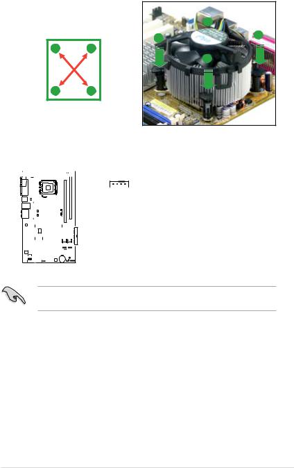
2.Push down two fasteners at a time in a diagonal sequence to secure the
heatsink and fan assembly in place. |
|
B |
|
|
|
||
|
|
A |
A |
|
|
|
|
A |
B |
|
|
|
|
|
B |
BA
3.Connect the CPU fan cable to the connector on the motherboard labeled CPU_FAN.


 CPU_FAN
|
|
|
|
|
|
|
|
|
|
|
|
|
|
|
|
|
|
|
C/1600- |
|
|
|
|
|
|
|
|
||
|
|
|
|
|
|
|
|
|
|
|
|
|
|
|
|
|
|
|
|
|
PWM |
PWR |
|||||||
|
|
|
|
|
|
|
|
|
|
|
|
|
|
|
|
|
|
||||||||||||
|
|
|
|
|
|
|
|
|
|
|
|
|
|
|
|
|
|
|
P5KPL |
|
|
|
|
IN |
GND |
||||
|
|
|
|
|
|
|
|
|
|
|
|
|
|
|
|
|
|
|
|||||||||||
|
|
|
|
|
|
|
|
|
|
|
|
|
|
|
|
|
|
|
|
|
|
|
|
|
|||||
|
|
|
|
|
|
|
|
|
|
|
|
|
|
|
|
|
|
|
|
|
FAN |
FAN |
|||||||
|
|
|
|
|
|
|
|
|
|
|
|
|
|
|
|
|
|
|
|
|
|
|
|
|
|
FAN |
|
|
|
|
|
|
|
|
|
|
|
|
|
|
|
|
|
|
|
|
|
|
|
|
|
|
|
|
|
CPU |
|
|
|
|
|
|
|
|
|
|
|
|
|
|
|
|
|
|
|
|
|
|
|
|
|
|
|
|
|
||||
|
|
|
|
|
|
|
|
|
|
|
|
|
|
|
|
|
|
|
|
|
|
|
|
|
|
||||
|
|
|
|
|
|
|
|
|
|
|
|
|
|
|
|
|
|
|
|
|
|
|
|
CPU |
CPU |
||||
|
|
|
|
|
|
|
|
|
|
|
|
|
|
|
|
|
|
|
|
|
|
|
|
|
|
|
|
|
|
|
|
|
|
|
|
|
|
|
|
|
|
|
|
|
|
|
|
|
|
|
|
|
|
|
|
|
|
|
|
|
|
|
|
|
|
|
|
|
|
|
|
|
|
|
|
|
|
|
|
|
|
|
|
|
|
|
|
|
|
|
|
|
|
|
|
|
|
|
|
|
|
|
|
|
|
|
|
|
|
|
|
|
|
|
|
|
|
|
|
|
|
|
|
|
|
|
|
|
|
|
|
|
|
|
|
|
|
|
|
|
|
|
|
|
|
|
|
|
|
|
|
|
|
|
|
|
|
|
|
|
|
|
|
|
|
|
|
|
|
|
|
|
|
|
|
|
|
|
|
|
|
|
|
|
|
|
|
|
|
|
|
|
|
|
|
|
|
|
|
|
|
|
|
|
|
|
|
|
|
P5KPL-C/1600 CPU Fan Connector
Do not forget to connect the CPU fan connector! Hardware monitoring errors can occur if you fail to plug this connector.
ASUS P5KPL-C/1600 |
1-15 |

1.6.3Uninstalling the CPU heatsink and fan
To uninstall the CPU heatsink and fan:
1.Disconnect the CPU fan cable from the connector on the motherboard.
2.Rotate each fastener counterclockwise.
3.Pull up two fasteners at a time in a diagonal sequence to disengage the heatsink and fan assembly from the motherboard.
B
A A
A |
B |
B |
BA
4.Carefully remove the heatsink and fan assembly from the motherboard.
1-16 |
Chapter 1: Product Introduction |

5.Rotate each fastener clockwise to ensure correct orientation when reinstalling.
The narrow end of the groove should point outward after resetting. (The photo shows the groove shaded for emphasis.)
Narrow end of the groove
Refer to the documentation in the boxed or stand-alone CPU fan package for detailed information on CPU fan installation.
ASUS P5KPL-C/1600 |
1-17 |
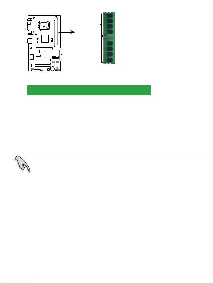
1.7System memory
1.7.1Overview
The motherboard comes with two Double Data Rate 2 (DDR2) Dual Inline Memory Modules (DIMM) sockets.
The figure illustrates the location of the DDR2 DIMM sockets:
A1 |
DIMM B1 |
DIMM_ |
|
P5KPL-C/1600 |
112 Pins |
|
128 Pins |
P5KPL-C/1600 240-pin DDR2 DIMM Sockets
Channel |
Sockets |
Channel A |
DIMM_A1 |
Channel B |
DIMM_B1 |
1.7.2Memory configurations
You may install 256MB, 512MB, 1GB and 2GB unbuffered non-ECC DDR2 DIMMs into the DIMM sockets.
•You may install varying memory sizes in Channel A and Channel B. The system maps the total size of the lower-sized channel for the dual-channel configuration. Any excess memory from the higher-sized channel is then mapped for single-channel operation.
•Always install DIMMs with the same CAS latency. For optimum compatibility, it is recommended that you obtain memory modules from the same vendor. Refer to the DDR2 Qualified Vendors List on the next page for details.
•If you are using a Windows 32-bit version operating system (e.g. 32-bit Windows XP, 32-bit Vista) without the Physical Address Extension (PAE) support, the system will allocate a certain amount of memory space for system devices.
•We recommend that you install only a maximum of 3GB system memory when using a Windows 32-bit version operating system without the PAE.
The excess over 3GB of installed memory will not cause any problem; however, the system can not use this excess memory space and the system will display less than the total size of physical memory installed.
1-18 |
Chapter 1: Product Introduction |
 Loading...