


P5W64 WS
Professional
Motherboard

E2743
First Edition V1
August 2006
Copyright © 2006 ASUSTeK COMPUTER INC. All Rights Reserved.
No part of this manual, including the products and software described in it, may be reproduced, transmitted, transcribed, stored in a retrieval system, or translated into any language in any form or by any means, except documentation kept by the purchaser for backup purposes, without the express written permission of ASUSTeK COMPUTER INC. (“ASUS”).
Product warranty or service will not be extended if: (1) the product is repaired, modified or altered, unless such repair, modification of alteration is authorized in writing by ASUS; or (2) the serial number of the product is defaced or missing.
ASUS PROVIDES THIS MANUAL “AS IS” WITHOUT WARRANTY OF ANY KIND, EITHER EXPRESS OR IMPLIED, INCLUDING BUT NOT LIMITED TO THE IMPLIED WARRANTIES OR CONDITIONS OF MERCHANTABILITY OR FITNESS FOR A PARTICULAR PURPOSE. IN NO EVENT SHALL ASUS, ITS DIRECTORS, OFFICERS, EMPLOYEES OR AGENTS BE LIABLE FOR ANY INDIRECT, SPECIAL, INCIDENTAL, OR CONSEQUENTIAL DAMAGES (INCLUDING DAMAGES FOR LOSS OF PROFITS, LOSS OF BUSINESS, LOSS OF USE OR DATA, INTERRUPTION OF BUSINESS AND THE LIKE), EVEN IF ASUS HAS BEEN ADVISED OF THE POSSIBILITY OF SUCH DAMAGES ARISING FROM ANY DEFECT OR ERROR IN THIS MANUAL OR PRODUCT.
SPECIFICATIONS AND INFORMATION CONTAINED IN THIS MANUAL ARE FURNISHED FOR INFORMATIONAL USE ONLY, AND ARE SUBJECT TO CHANGE AT ANY TIME WITHOUT NOTICE, AND SHOULD NOT BE CONSTRUED AS A COMMITMENT BY ASUS. ASUS ASSUMES NO RESPONSIBILITY OR LIABILITY FOR ANY ERRORS OR INACCURACIES THAT MAY APPEAR IN THIS MANUAL, INCLUDING THE PRODUCTS AND SOFTWARE DESCRIBED IN IT.
Products and corporate names appearing in this manual may or may not be registered trademarks or copyrights of their respective companies, and are used only for identification or explanation and to the owners’ benefit, without intent to infringe.
i i

Contents
Notices ............................................................................................... |
|
vii |
|
Safety information ............................................................................ |
viii |
||
About this guide ................................................................................. |
ix |
||
P5W64 WS Professional specifications summary ............................... |
xi |
||
Chapter 1: Product introduction |
|
||
1.1 |
Welcome! .............................................................................. |
1-1 |
|
1.2 |
Package contents ................................................................. |
1-1 |
|
1.3 |
Special features .................................................................... |
1-2 |
|
|
1.3.1 |
Product highlights................................................... |
1-2 |
|
1.3.2 ASUS Intelligence (AI) features .............................. |
1-5 |
|
|
1.3.3 |
Innovative ASUS features ....................................... |
1-6 |
Chapter 2: Hardware information |
|
||
2.1 |
Before you proceed .............................................................. |
2-1 |
|
2.2 |
Motherboard overview .......................................................... |
2-2 |
|
|
2.2.1 |
Placement direction ................................................ |
2-2 |
|
2.2.2 |
Screw holes ............................................................ |
2-2 |
|
2.2.3 ASUS Stack Cool 2 ................................................. |
2-3 |
|
|
2.2.4 |
Motherboard layout ................................................ |
2-4 |
|
2.2.5 |
Layout contents ..................................................... |
2-5 |
2.3 |
Central Processing Unit (CPU) .............................................. |
2-7 |
|
|
2.3.1 |
Installing the CPU.................................................... |
2-8 |
|
2.3.2 Installing the CPU heatsink and fan ...................... |
2-10 |
|
|
2.3.3 Uninstalling the CPU heatsink and fan .................. |
2-12 |
|
2.4 |
System memory ................................................................. |
2-14 |
|
|
2.4.1 |
Overview ............................................................... |
2-14 |
|
2.4.2 |
Memory configurations ......................................... |
2-14 |
|
2.4.3 |
Installing a DIMM ................................................... |
2-19 |
|
2.4.4 |
Removing a DIMM ................................................. |
2-19 |
2.5 |
Expansion slots ................................................................... |
2-20 |
|
|
2.5.1 Installing an expansion card .................................. |
2-20 |
|
|
2.5.2 Configuring an expansion card.............................. |
2-20 |
|
|
2.5.3 |
Interrupt assignments .......................................... |
2-21 |
|
2.5.4 PCI Express x16 slots ........................................... |
2-22 |
|
|
2.5.5 |
PCI slots ................................................................ |
2-22 |
2.6 |
Jumpers |
.............................................................................. |
2-27 |
2.7 |
Connectors ......................................................................... |
2-28 |
|
|
2.7.1 |
Rear panel connectors .......................................... |
2-28 |
|
2.7.2 |
Internal connectors............................................... |
2-31 |
i i i

Contents
Chapter 3: Powering up
3.1 Starting up for the first time................................................ |
3-1 |
||
3.2 Turning off the computer ..................................................... |
3-2 |
||
|
3.2.1 Using the OS shut down function ........................... |
3-2 |
|
|
3.2.2 Using the dual function power switch .................... |
3-2 |
|
Chapter 4: BIOS setup |
|
||
4.1 Managing and updating your BIOS ........................................ |
4-1 |
||
|
4.1.1 |
ASUS Update utility ................................................ |
4-1 |
|
4.1.2 Creating a bootable floppy disk .............................. |
4-4 |
|
|
4.1.3 ASUS EZ Flash 2 utility ........................................... |
4-5 |
|
|
4.1.4 |
AFUDOS utility ........................................................ |
4-6 |
|
4.1.5 ASUS CrashFree BIOS 3 utility ................................ |
4-9 |
|
4.2 |
BIOS setup program ........................................................... |
4-11 |
|
|
4.2.1 |
BIOS menu screen................................................. |
4-12 |
|
4.2.2 |
Menu bar ............................................................... |
4-12 |
|
4.2.3 |
Navigation keys .................................................... |
4-12 |
|
4.2.4 |
Menu items ........................................................... |
4-13 |
|
4.2.5 |
Sub-menu items ................................................... |
4-13 |
|
4.2.6 |
Configuration fields .............................................. |
4-13 |
|
4.2.7 |
Pop-up window ..................................................... |
4-13 |
|
4.2.8 |
Scroll bar .............................................................. |
4-13 |
|
4.2.9 |
General help .......................................................... |
4-13 |
4.3 |
Main menu .......................................................................... |
4-14 |
|
|
4.3.1 |
System Time......................................................... |
4-14 |
|
4.3.2 |
System Date ......................................................... |
4-14 |
|
4.3.3 |
Legacy Diskette A ................................................ |
4-14 |
|
4.3.4 |
Language .............................................................. |
4-14 |
|
4.3.5 Primary, Third, and Fourth IDE Master/Slave ........ |
4-15 |
|
|
4.3.6 |
IDE Configuration .................................................. |
4-16 |
|
4.3.7 |
System Information .............................................. |
4-18 |
4.4 |
Advanced menu .................................................................. |
4-19 |
|
|
4.4.1 |
JumperFree Configuration .................................... |
4-19 |
|
4.4.2 |
LAN Cable Status ................................................. |
4-23 |
|
4.4.3 |
USB Configuration................................................. |
4-24 |
|
4.4.4 |
CPU Configuration................................................. |
4-26 |
|
4.4.5 |
Chipset ................................................................. |
4-28 |
|
4.4.6 |
Onboard Devices Configuration ............................ |
4-30 |
|
4.4.7 |
PCI PnP ................................................................. |
4-32 |
i v

Contents
4.5 |
Power menu ........................................................................ |
4-32 |
|
|
4.5.1 |
Suspend Mode ...................................................... |
4-33 |
|
4.5.2 Repost Video on S3 Resume ................................ |
4-33 |
|
|
4.5.3 |
ACPI 2.0 Support .................................................. |
4-33 |
|
4.5.4 |
ACPI APIC Support ................................................ |
4-34 |
|
4.5.5 |
APM Configuration ................................................ |
4-34 |
|
4.5.6 |
Hardware Monitor ................................................. |
4-36 |
4.6 |
Boot menu .......................................................................... |
4-38 |
|
|
4.6.1 |
Boot Device Priority .............................................. |
4-38 |
|
4.6.2 |
Removable Drives ................................................. |
4-39 |
|
4.6.3 |
Boot Settings Configuration ................................. |
4-41 |
4.7 |
Tools |
................................................................................... |
4-44 |
|
4.7.1 ASUS EZ Flash 2 ................................................... |
4-44 |
|
|
4.7.2 .................................................. |
ASUS O.C. Profile |
4-45 |
4.8 |
Exit menu ........................................................................... |
4-47 |
|
Chapter 5: Software support |
|
||
5.1 |
Installing .............................................an operating system |
5-1 |
|
5.2 |
Support ........................................................CD information |
5-1 |
|
|
5.2.1 .........................................Running the support CD |
5-1 |
|
|
5.2.2 .......................................................... |
Drivers menu |
5-2 |
|
5.2.3 .......................................................... |
Utilities menu |
5-3 |
|
5.2.4 ...................................................... |
Make Disk menu |
5-5 |
|
5.2.5 ......................................................... |
Manuals menu |
5-6 |
|
5.2.6 ............................................... |
Contact information |
5-6 |
|
5.2.7 ................................................... |
Other information |
5-7 |
5.3 |
Software ...........................................................information |
5-9 |
|
|
5.3.1 .................................................... |
ASUS MyLogo2™ |
5-9 |
|
5.3.2 ................................................................ |
AI NET2 |
5-11 |
|
5.3.3 .................................................................. |
AI Gear |
5-12 |
|
5.3.4 ................................................................... |
AI Nap |
5-14 |
|
5.3.5 ............................................................. |
AI Booster |
5-15 |
|
5.3.6 ...................................................ASUS PC Probe II |
5-16 |
|
|
5.3.7 ..............SoundMAX® High Definition Audio utility |
5-22 |
|
5.4 |
RAID ............................................................configurations |
5-27 |
|
|
5.4.1 .............................Installing Serial ATA hard disks |
5-28 |
|
|
5.4.2 ................................... |
Intel® RAID configurations |
5-28 |
5.5 |
Creating .................................................a RAID driver disk |
5-39 |
|
v

Appendix: CPU features
A.1 |
Intel® EM64T ........................................................................ |
A-1 |
A.2 |
Enhanced Intel SpeedStep® Technology (EIST) .................... |
A-1 |
A.3 |
Intel® Hyper-Threading Technology ...................................... |
A-3 |
v i

Notices
Federal Communications Commission Statement
This device complies with Part 15 of the FCC Rules. Operation is subject to the following two conditions:
•This device may not cause harmful interference, and
•This device must accept any interference received including interference that may cause undesired operation.
This equipment has been tested and found to comply with the limits for a Class B digital device, pursuant to Part 15 of the FCC Rules. These limits are designed to provide reasonable protection against harmful interference in a residential installation. This equipment generates, uses and can radiate radio frequency energy and, if not installed and used in accordance with manufacturer’s instructions, may cause harmful interference to radio communications. However, there is no guarantee that interference will not occur in a particular installation. If this equipment does cause harmful interference to radio or television reception, which can be determined by turning the equipment off and on, the user is encouraged to try to correct the interference by one or more of the following measures:
•Reorient or relocate the receiving antenna.
•Increase the separation between the equipment and receiver.
•Connect the equipment to an outlet on a circuit different from that to which the receiver is connected.
•Consult the dealer or an experienced radio/TV technician for help.
The use of shielded cables for connection of the monitor to the graphics card is required to assure compliance with FCC regulations. Changes or modifications to this unit not expressly approved by the party responsible for compliance could void the user’s authority to operate this equipment.
Canadian Department of Communications Statement
This digital apparatus does not exceed the Class B limits for radio noise emissions from digital apparatus set out in the Radio Interference Regulations of the Canadian Department of Communications.
This class B digital apparatus complies with Canadian ICES-003.
v i i

Safety information
Electrical safety
•To prevent electrical shock hazard, disconnect the power cable from the electrical outlet before relocating the system.
•When adding or removing devices to or from the system, ensure that the power cables for the devices are unplugged before the signal cables are connected. If possible, disconnect all power cables from the existing system before you add a device.
•Before connecting or removing signal cables from the motherboard, ensure that all power cables are unplugged.
•Seek professional assistance before using an adpater or extension cord. These devices could interrupt the grounding circuit.
•Make sure that your power supply is set to the correct voltage in your area. If you are not sure about the voltage of the electrical outlet you are using, contact your local power company.
•If the power supply is broken, do not try to fix it by yourself. Contact a qualified service technician or your retailer.
Operation safety
•Before installing the motherboard and adding devices on it, carefully read all the manuals that came with the package.
•Before using the product, make sure all cables are correctly connected and the power cables are not damaged. If you detect any damage, contact your dealer immediately.
•To avoid short circuits, keep paper clips, screws, and staples away from connectors, slots, sockets and circuitry.
•Avoid dust, humidity, and temperature extremes. Do not place the product in any area where it may become wet.
•Place the product on a stable surface.
•If you encounter technical problems with the product, contact a qualified service technician or your retailer.
The symbol of the crossed out wheeled bin indicates that the product (electrical and electronic equipment) should not be placed in municipal waste. Please check local regulations for disposal of electronic products.
viii

About this guide
This user guide contains the information you need when installing and configuring the motherboard.
How this guide is organized
This user guide contains the following parts:
•Chapter 1: Product introduction
This chapter describes the features of the motherboard and the new technology it supports.
•Chapter 2: Hardware information
This chapter lists the hardware setup procedures that you have to perform when installing system components. It includes description of the switches, jumpers, and connectors on the motherboard.
•Chapter 3: Powering up
This chapter describes the power up sequence and ways of shutting down the system.
•Chapter 4: BIOS setup
This chapter tells how to change system settings through the BIOS Setup menus. Detailed descriptions of the BIOS parameters are also provided.
•Chapter 5: Software support
This chapter describes the contents of the support CD that comes with the motherboard package.
•Appendix: CPU features
The Appendix describes the CPU features and technologies that the motherboard supports.
Where to find more information
Refer to the following sources for additional information and for product and software updates.
1 . ASUS websites
The ASUS website provides updated information on ASUS hardware and software products. Refer to the ASUS contact information.
2 . Optional documentation
Your product package may include optional documentation, such as warranty flyers, that may have been added by your dealer. These documents are not part of the standard package.
i x

Conventions used in this guide
To make sure that you perform certain tasks properly, take note of the following symbols used throughout this manual.
DANGER/WARNING: Information to prevent injury to yourself when trying to complete a task.
CAUTION: Information to prevent damage to the components when trying to complete a task.
IMPORTANT: Instructions that you MUST follow to complete a task.
NOTE: Tips and additional information to help you complete a task.
Typography
Bold text |
Indicates a menu or an item to select. |
Italics |
Used to emphasize a word or a phrase. |
<Key> |
Keys enclosed in the less-than and greater-than |
|
sign means that you must press the enclosed key. |
|
Example: <Enter> means that you must press |
|
the Enter or Return key. |
<Key1+Key2+Key3> |
If you must press two or more keys |
|
simultaneously, the key names are linked with a |
|
plus sign (+). |
|
Example: <Ctrl+Alt+D> |
Command |
Means that you must type the command exactly |
|
as shown, then supply the required item or value |
|
enclosed in brackets. |
|
Example: At the DOS prompt, type the command |
|
line: |
|
afudos /i[filename] |
|
afudos /iW64WSPRO.ROM |
x
P5W64 WS Professional specifications summary
C P U
Chipset
Front Side Bus
Memory
Expansion slots
CrossFire™
Storage
L A N
High Definition
Audio
LGA775 socket for Intel® Pentium® 4/Celeron® processor
Supports Intel® Pentium® Processor Extreme Edition and Intel® Pentium® D Processor
Supports Intel® next generation 65nm and Intel® Core™ 2 Duo/Intel® Core™ 2 Extreme processors
Supports Intel® next generation Multi-Core processor Compatible with Intel® 06B, 05B/05A and 04B/04A
processors
Supports Intel® EIST/EM64T/Hyper-Threading Technology
Northbridge: Intel® 975X (suppports ATi CorssFire dual Gfx technology)
Southbridge: Intel® ICH7R PCI-E Switch: IDT89HA0324
1066/800 MHz
Dual-channel memory architecture
4 x 240-pin DIMM sockets support up to 8 GB system memory unbufferred ECC/non-ECC DDR2 667/ 533 MHz memory modules
Native DDR2 800 support
4 x PCI Express™ x16 slots for discrete graphics cards (at x8, x8, x4, x8 mode or at x16, x0, x4, x0 mode)
2 x PCI 2.2 slots
Supports ATi CrossFire™ graphics cards
Intel® ICH7R Southbridge supports:
-1 x IDE connector for up to two Ultra DMA 100/66/33 hard disks
-4 x Serial ATA I/II 3.0 Gb/s hard disks with RAID 0, RAID 1, RAID 10, and RAID 5 configuration
-Intel® Matrix Storage Technology
Marvell® 88SE6145 Serial ATA controller supports:
-3 x Serial ATA I/II 3.0 Gb/s hard disks
-1 X External Serial ATA hard disk
Marvell® 88E8052+88E8001 Dual Gigabit LAN controllers - Support teaming function
High definition audio, ADI® AD1988B SoundMax 7.1 channel CODEC
Supports Multi-streaming, Enumeration, Jack-sensing, and Jack-retasking functions
Coaxial and optical S/PDIF out ports
(continued on the next page)
x i

P5W64 WS Professional specifications summary
IEEE 1394a
U S B
ASUS special features - Performance
ASUS special features - Thermal
ASUS special features - Life
ASUS special features - Others
BIOS features
T1 1394a controller supports: - 2 x IEEE 1394a ports
Supports up to 8 USB 2.0 ports
Intelligent overclocking tools:
-AI NOS™ (Non-delay Overclocking System)
-AI Overclocking (intelligent CPU frequency tuner)
-AI Clock Skew
-ASUS PEG Link (automatic performance tuning for single/dual graphics cards)
-ASUS BIOS Profile
- ASUS C.P.R. (CPU Parameter Recall) |
- |
-ASUS AI Booster
-Adjustable FSB/DDR2 ratio. Fixed PCI/PCIe frequencies.
-Hyper Path 3
Precision Tweaker:
-vDIMM: 12-step DRAM voltage control
-vCore: Adjustable CPU voltage at 0.0125 V increment
-Stepless Frequency Selection(SFS): allowing FSB tuning from 100 MHz up to 550 MHz at 1 MHz increment
-PCI Express x16 frequency: allowing PCI Express x16 frequency tuning from 9 0 MHz to 150 MHz at 1 MHz increment
ASUS 8-Phase Power Design
Stack Cool 2
Q-Fan 2
ASUS Heat-pipe thermal solution
Multi-language BIOS
SATA on the Go
AI Nap
AI Gear
My Logo 2
CrashFree BIOS 3
EZ Flash 2
ASUS AI NET 2
Q-Connector
ASUS AI Quiet
TPM (Trusted Platform Module) 1.2 (optional)
8 Mb Flash ROM, AMI BIOS, Green PnP, DMI, Wfm2.0, ACPI v2.0a, SMBIOS v2.3, EZ Flash, CrashFree BIOS
(continued on the next page)
x i i

P5W64 WS Professional specifications summary
Rear panel
Internal connectors
Support CD contents
Manageability
Form Factor
1 x PS/2 mouse port
1 x PS/2 keyboard port
1 x Parallel port
2 x LAN (RJ-45) ports
1 x Coaxial S/PDIF Out port
1 x Optical S/PDIF Out port
1 x eSATA port
4 x USB 2.0 ports
8-Channel audio ports
1 x Floppy disk drive connector
1 x Primary IDE connector
4 x ICH7R Serial ATA connectors
4 x Marvell® 88SE6145 Serial ATA RAID connectors
1 x Optical drive audio connector
1 x Front panel audio connector
2 x USB connectors for four additional USB 2.0 ports 2 x IEEE 1394a port connector
1 x Chassis intrusion connector
1 x CPU fan connector
2 x Chassis fan connectors
1 x Power fan connector
1 x EZ Plug connector
1 x Serial port (COM1) connector
EATX power connectors (24-pin and 2 x 4-pin) System panel connector
Device drivers
BIOS Flash Utility under DOS
ASUS AI Booster
ASUS PC Probe 2
Anti virus software
Microsoft® DirectX 9.0c
Adobe® Acrobat Reader® 7.0
RAID Utility
WOL by PME, WOR by PME, chassis intrusion, PXE, AI NET
ATX form factor: 12 in x 9.6 in (30.5 cm x 24.5 cm)
*Specifications are subject to change without notice.
xiii

x i v
This chapter describes the motherboard
features and the new technologies 1 it supports.
Product introduction

Chapter summary |
1 |
1.1 |
Welcome! .............................................................................. |
1-1 |
1.2 |
Package contents ................................................................. |
1-1 |
1.3 |
Special features .................................................................... |
1-2 |
ASUS P5W64 WS Professional

1.1Welcome!
Thank you for buying an ASUS® P5W64 WS Professional Workstation motherboard!
The motherboard delivers a host of new features and latest technologies, making it another standout in the long line of ASUS quality motherboards!
Before you start installing the motherboard, and hardware devices on it, check the items in your package with the list below.
1.2Package contents
Check your motherboard package for the following items.
Motherboard |
ASUS P5W64 WS PRO motherboard |
|
I/O modules |
1 x 2-port IEEE 1394a module |
|
|
|
1 x 2-port USB 2.0 module |
Cables |
1 x Floppy disk drive cable |
|
|
|
1 x Ultra DMA 133/100/66 cable |
|
|
7 x Serial ATA signal cables |
|
|
4 x Serial ATA power cables for up to 7 devices |
Accessories |
I/O shield |
|
|
|
|
Application CD |
ASUS motherboard support CD |
|
|
|
InterVideo® Media Launcher |
Documentation |
User guide |
|
|
|
|
|
|
|
If any of the above items is damaged or missing, contact your retailer.
ASUS P5W64 WS Professional |
1 - 1 |

1.3Special features
1.3.1Product highlights
Latest processor technology 
The motherboard comes with a 775-pin surface mount Land Grid Array (LGA) socket designed for the Intel® Pentium® 4/Celeron®/Pentium® D/ Pentium® Processor Extreme Edition in the 775-land package with 1066/ 800/533 MHz Front Side Bus (FSB). The motherboard also supports the Intel® Hyper-Threading Technology and is fully compatible with Intel® 05B/ 05A and 04B/04A processors. See page 2-7 for details.
Intel® Core™2 Duo/ Intel® Core™2 Extreme CPU support
This motherboard supports the latest powerful and energy efficient processors from Intel®. Intel® Core™2 Duo and Intel® Core™2 Extreme are based on the Intel® Core™ Microarchitecture and built on the 65-nanometer (nm) process technology with copper interconnect. Intel® Core™2 Duo and Intel® Core™2 Extreme allow users to step up to new levels of gaming experience and multi-tasking performance. Boosting performance is a shared and multi-core optimized L2 cache of 2 MB or 4 MB, guaranteeing enhanced user experience in the digital home and office.
Intel® 65nm Dual-Core CPU support 
This motherboard supports Intel® Pentium® D/Pentium® 4/Celeron® dual-core processors built on the 65-nanometer (nm) process technology with copper interconnect. Dual-core processors contain two physical
CPU cores with dedicated L2 caches to meet demands for more powerful processing. Intel®’s 65nm process is the most advanced chip manufacturing technology, delivering breakthrough performance, enhanced media experience, and low power consumption. Intel® 65nm dual-core processors utilize the latest package technologies for a thinner, lighter design without compromising performance.
1 - 2 |
Chapter 1: Product introduction |

Intel® 975X Express/ICH7R chipset
The Intel® 975X Express Memory Controller Hub (MCH) and the ICH7R I/O controller hub provide the vital interfaces for the motherboard. The Intel® 975X Express is the latest chipset designed to support Dual PCI Express graphics, along with the maximum 8 GB dual-channel DDR2 800/667/533 MHz, 1066/800/533 FSB, and dual-core CPU. The MCH also supports the Intel® Memory Pipeline Technology (MPT) that boosts system performance.
The Intel® ICH7R Southbridge integrates four Serial ATA I/II connectors enabled through the Serial ATA 3 Gb/s RAID controller to ensure data security and enable powerful multi-task processing.
Intel® EM64T 
The motherboard supports Intel® Pentium® 4 CPUs with the Intel® EM64T (Extended Memory 64 Technology). The Intel® EM64T feature allows your computer to run on 64-bit operating systems and access larger amounts of system memory for faster and more efficient computing. See the Appendix for details.
Intel® Memory Pipeline Technology (MPT) 
The Intel® MPT increases system-level and standard operating performance by optimizing memory access between CPU and system memory.
Enhanced Intel SpeedStep® Technology (EIST)
The Enhanced Intel SpeedStep® Technology (EIST) intelligently manages the CPU resources by automatically adjusting the CPU voltage and core frequency depending on the CPU loading and system speed or power requirement. See page 4-27 and the Appendix for details.
DDR2 memory support 


The motherboard supports DDR2 memory, which features data transfer rates of 800/667/533 MHz to meet the higher bandwidth requirements of the latest 3D graphics, multimedia, and Internet applications. The dual-channel DDR2 architecture doubles the bandwidth of your system memory to boost system performance, eliminating bottlenecks with peak bandwidths of up to 10.7 GB/s. See page 2-14 for details.
ASUS P5W64 WS Professional |
1 - 3 |

Serial ATA I/II technology and SATA-On-The-Go
The motherboard supports the Serial ATA 3 Gb/s technology through the Serial ATA interfaces and the Intel® ICH7R chipset. The Serial ATA 3 Gb/s specification provides twice the bandwidth of the current Serial ATA products with a host of new features, including Native Command Queuing (NCQ), Power Management (PM) Implementation Algorithm, and Hot Swap. Serial ATA allows thinner, more flexible cables with lower pin count and reduced voltage requirements. Leveraging these Serial ATA 3.0 Gb/s features is the SATA-On-The-Go. Supported by the Marvell® 88SE6145 Serial ATA controller, four Serial ATA 3.0 Gb/s connectors (three at midboard and one on the rear panel) provide smart setup, and hot-plug function. See pages 2-35 and 2-36 for details.
PCI Express™ interface
The motherboard fully supports PCI Express, the latest I/O interconnect technology that speeds up the PCI bus. PCI Express features point-to-point serial interconnections between devices and allows higher clockspeeds by carrying data in packets. This high speed interface is software compatible with existing PCI specifications. See page 2-23 for details.
S/PDIF digital sound ready 
The motherboard supports the S/PDIF technology through the S/PDIF interfaces on the rear panel. The S/PDIF technology turns your computer into a high-end entertainment system with digital connectivity to powerful audio and speaker systems. See page 2-33 for details.
8-channel high definition audio 
Onboard is the ADI AD1988B High Definition Audio 8-channel audio CODEC. This CODEC is fully-compliant with Intel® High Definition Audio standard (192 KHz, 24-bit audio). With the CODEC, 8-channel audio ports, and S/ PDIF interfaces, you can connect your computer to home theater decoders to produce crystal-clear digital audio.
USB 2.0 technology 
The motherboard implements the Universal Serial Bus (USB) 2.0 specification, dramatically increasing the connection speed from the
12 Mbps bandwidth on USB 1.1 to a fast 480 Mbps on USB 2.0. USB 2.0 is backward compatible with USB 1.1. See pages 2-33 and 2-38 for details.
1 - 4 |
Chapter 1: Product introduction |
IEEE 1394a support 
The motherboard supports the IEEE 1394a interface that provides high-speed and flexible PC connectivity to a wide range of peripherals and devices compliant to IEEE 1394a standards. The IEEE 1394a interface allows up to 400 Mbps transfer rates through simple , low-cost, high-bandwidth asynchronous (real-time) data interfacing between computers, peripherals, and consumer electronic devices such as camcorders, VCRs, printers, TVs, and digital cameras. See pages 2-33 and 2-38 for details.
Dual Gigabit LAN solution
The motherboard comes with dual Gigabit LAN controllers to provide the total solution for your networking needs. These network controllers use the PCI Express and PCI segments to provide faster data bandwidth for your wired or wireless Internet, LAN, and file sharing requirements. See page 2- 32 for details.
Trusted Platform Module (TPM) [optional]
The Trusted Platform Module (TPM) is a secure microcontroller hardware component with embedded software. The motherboard implements the optional module to provide the first link in the chain of trust, providing convenient single sign-on to systems and enable digital signatures for secure transactions.See page 2-43 for details.
1.3.2ASUS Intelligence (AI) features
ASUS Stack Cool 2 
ASUS Stack Cool 2 is a fan-less and zero-noise cooling solution that lowers the temperature of critical heat generating components by 20ºC. The motherboard uses a special design on the printed circuit board (PCB) to dissipate heat that critical components generate. See page 2-3 for details.
AI Quiet 
The ASUS AI Quiet function dynamically controls CPU speed and reduces temperature and fan speeds, thus minimizing noise and ensuring quiet operation. See page 4-35 for details.
ASUS P5W64 WS Professional |
1 - 5 |

1.3.3Innovative ASUS features
Native DDR2-800 memory support 
Native DDR2-800 eliminates the bottleneck when overclocking both the CPU and the memory, thus maximizing performance for 3D graphics and other system-intensive applications. See pages 2-16 and 4-20 for details.
AI Overclocking
This feature allows convenient overclocking up to 30 percent (depending on the installed CPU and DRAM) to enhance system performance while still maintaining system stability. See page 4-19 to set the BIOS items for overclocking.
AI NET2 
AI NET2 is a BIOS-based diagnostic tool that detects and reports Ethernet cable faults and shorts. With this utility, you can easily monitor the condition of the Ethernet cable connected to the LAN (RJ-45) port. During the bootup process, AI NET2 immediately diagnoses the LAN cable and reports shorts and faults up to 100 meters at 1 meter accuracy. See pages 4-23 and 5-13 for details.
PEG Link Mode 
This feature enhances your PCI Express graphics card performance by allowing the motherboard to automatically adjust the PCI Express graphics link mode to the correct frequency based on the system configuration. Four additional settings are available for overclocking the PEG Link Mode. See page 4-28 for details.
CPU Lock Free
This feature allows you to adjust the CPU multiplier to 14x. Setting the appropriate BIOS setting automatically reduces the CPU multiplier value for more flexibility when increasing external FSB. See page 4-20 for details.
1 - 6 |
Chapter 1: Product introduction |

ASUS Q-Fan 2 technology 
The ASUS Q-Fan 2 technology smartly adjusts the fan speeds according to the system loading to ensure quiet, cool, and efficient operation.
See page 4-35 for details.
ASUS Multi-language BIOS 
The multi-language BIOS allows you to select the language of your choice from the available options. The localized BIOS menus allow easier and faster configuration. See page 4-14 for details.
ASUS MyLogo2™ 
This new feature present in the motherboard allows you to personalize and add style to your system with customizable boot logos. See pages 4-38 and 5-11 for details.
ASUS CrashFree BIOS 3 
This feature allows you to restore the original BIOS data from the support CD in case when the BIOS codes and data are corrupted. This protection eliminates the need to buy a replacement ROM chip. See page 4-9 for details.
ASUS EZ Flash 2 BIOS 
With the ASUS EZ Flash 2, you can easily update the system BIOS even before loading the operating system. No need to use a DOS-based utility or boot from a floppy disk. See page 4-5 for details.
ASUS P5W64 WS Professional |
1 - 7 |

1 - 8 |
Chapter 1: Product introduction |
This chapter lists the hardware setup |
2 |
|
procedures that you have to perform |
||
|
||
when installing system components. It |
|
|
includes description of the jumpers and |
Hardware |
|
connectors on the motherboard. |
||
|
||
information |
||

Chapter summary |
2 |
2.1 |
Before you proceed .............................................................. |
2-1 |
2.2 |
Motherboard overview .......................................................... |
2-2 |
2.3 |
Central Processing Unit (CPU) .............................................. |
2-7 |
2.4 |
System memory ................................................................. |
2-14 |
2.5 |
Expansion slots ................................................................... |
2-20 |
2.6 |
Jumpers .............................................................................. |
2-27 |
2.7 |
Connectors ......................................................................... |
2-28 |
ASUS P5W64 WS Professional
2.1Before you proceed
Take note of the following precautions before you install motherboard components or change any motherboard settings.
•Unplug the power cord from the wall socket before touching any
component.
•Use a grounded wrist strap or touch a safely grounded object or a metal object, such as the power supply case, before handling components to avoid damaging them due to static electricity.
•Hold components by the edges to avoid touching the ICs on them.
•Whenever you uninstall any component, place it on a grounded antistatic pad or in the bag that came with the component.
•Before you install or remove any component, ensure that the ATX power supply is switched off or the power cord is detached from the power supply. Failure to do so may cause severe damage to the motherboard, peripherals, and/or components.
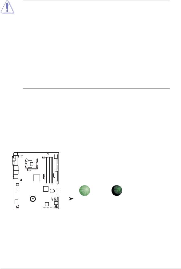
Onboard LED
The motherboard comes with a standby power LED. The green LED lights up to indicate that the system is ON, in sleep mode, or in soft-off mode. This is a reminder that you should shut down the system and unplug the power cable before removing or plugging in any motherboard component. The illustration below shows the location of the onboard LED.
P5W64 WS PRO
SB_PWR
|
|
|
|
|
|
|
|
|
|
|
|
|
|
|
|
|
|
|
|
|
|
|
|
|
|
|
|
|
|
|
|
|
|
|
|
|
|
|
|
|
|
ON |
OFF |
|
|
|
|
|
|
|
|
|
|
|
|
|
|
|
|
|
|
|
|
|
|
|
|
|
|
|
|
|
|
|
|
|
|
|
|
|
|
|
|
|
|
||
|
|
|
|
|
|
|
|
|
|
|
|
|
|
|
|
|
|
|
|
|
|
|
|
|
|
|
|
|
|
|
|
|
|
|
|
|
|
|
|
|
|
||
|
|
|
|
|
|
|
|
|
|
|
|
|
|
|
|
|
|
|
|
|
|
|
|
|
|
|
|
|
|
|
|
|
|
|
|
|
|
|
|
|
|
||
|
|
|
|
|
|
|
|
|
|
|
|
|
|
|
|
|
|
|
|
|
|
|
|
|
|
|
|
|
|
|
|
|
|
|
|
|
|
|
|
|
|
||
|
|
|
|
|
|
|
|
|
|
|
|
|
|
|
|
|
|
|
|
|
|
|
|
|
|
|
|
|
|
|
|
|
|
|
|
|
|
|
|
|
|
Standby |
Powered |
|
|
|
|
|
|
|
|
|
|
|
|
|
|
|
|
|
|
|
|
|
|
|
|
|
|
||||||||||||||||||
|
|
|
|
|
|
|
|
|
|
|
|
|
|
|
|
|
|
|
|
|
|
|
|
|
|
|
|
|
|
|
|
|
|
|
|
|
|
|
|
|
|
Power |
Off |
|
|||||||||||||||||||||||||||||||||||||||||||
|
|
|
|
|
|
|
|
|
|
|
|
|
|
|
|
|
|
|
|
|
|
|
|
|
|
|
|
|
|
|
|
|
|
|
|
|
|
|
|
P5W64 WS PRO Onboard LED
ASUS P5W64 WS Professional |
2 - 1 |
2.2Motherboard overview
Before you install the motherboard, study the configuration of your chassis to ensure that the motherboard fits into it.
Make sure to unplug the power cord before installing or removing the motherboard. Failure to do so can cause you physical injury and damage motherboard components.
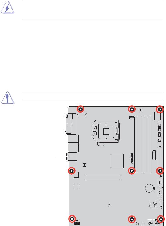
2.2.1Placement direction
When installing the motherboard, make sure that you place it into the chassis in the correct orientation. The edge with external ports goes to the rear part of the chassis as indicated in the image below.
2.2.2Screw holes
Place nine (9) screws into the holes indicated by circles to secure the motherboard to the chassis.
Do not overtighten the screws! Doing so can damage the motherboard.
Place this side towards the rear of the chassis
® P5W64 WS PRO |
|
|
|
|
|
|
|
|
|
|
|
|
|
|
|
|
|
|
|
|
|
|
|
|
|
|
|
|
|
|
|
|
|
|
|
|
|
|
|
|
|
|
|
|
|
|
|
|
|
|
|
|
|
|
|
|
|
|
|
|
|
|
|
|
|
|
|
|
|
|
|
|
|
|
|
|
|
|
|
|
|
|
|
|
|
|
|
|
|
|
|
|
|
|
|
|
|
|
|
|
|
|
|
|
|
|
|
|
|
|
|
|
|
|
|
|
|
|
|
|
|
|
|
|
|
|
|
|
|
|
|
|
|
|
|
|
|
|
|
|
|
|
|
|
|
|
|
|
|
|
|
|
|
|
|
|
|
|
|
|
|
|
|
|
|
|
|
|
|
|
|
|
|
|
|
|
|
|
|
|
|
|
|
|
|
|
|
|
|
|
|
|
|
|
|
|
|
|
|
|
|
|
|
|
|
|
|
|
|
|
|
|
|
|
|
|
|
|
|
|
|
|
|
|
|
|
|
|
|
|
|
|
|
|
|
|
|
|
|
|
|
|
|
|
|
|
|
|
|
|
|
|
|
|
|
|
|
|
|
|
|
|
|
|
|
|
|
|
|
|
|
|
|
|
|
|
|
|
|
|
|
|
|
|
|
|
|
|
|
|
|
|
|
|
|
|
|
|
|
|
|
|
|
|
|
|
|
|
|
|
|
|
|
|
|
|
|
|
|
|
|
|
|
|
|
|
|
|
|
|
|
|
|
|
|
|
|
|
|
|
|
|
|
|
|
|
|
|
|
|
|
|
|
|
|
|
|
|
|
|
|
|
|
|
|
|
|
|
|
|
|
|
|
|
|
|
|
|
|
|
|
|
|
|
|
|
|
|
|
|
|
|
|
|
|
|
|
|
|
|
|
|
|
|
|
|
|
|
|
|
|
|
|
|
|
|
|
|
|
|
|
|
|
|
|
|
|
|
|
|
|
|
|
|
|
|
|
|
|
|
|
|
|
|
|
|
|
|
|
|
|
|
|
|
|
|
|
|
|
|
|
|
|
|
|
|
|
|
|
|
|
|
|
|
|
|
|
|
|
|
|
|
|
|
|
|
|
|
|
|
|
|
|
|
|
|
|
|
|
|
|
|
|
|
|
|
|
|
|
|
|
|
|
|
|
|
|
|
|
|
|
|
|
|
|
|
|
|
|
|
|
|
|
|
|
|
|
|
|
|
|
|
|
|
|
|
|
|
|
|
|
|
|
|
|
|
|
|
|
|
|
|
|
|
|
|
|
|
|
|
|
|
|
|
|
|
|
|
|
|
|
|
|
|
|
|
|
|
|
|
|
|
|
|
|
|
|
|
|
|
|
|
|
|
|
|
|
|
|
|
|
|
|
|
|
|
|
|
|
|
|
|
|
|
|
|
|
|
|
|
|
|
|
|
|
|
|
|
|
|
|
|
|
|
|
|
|
|
|
|
|
|
|
|
|
|
|
|
|
|
|
|
|
|
|
|
|
|
|
|
|
|
|
|
|
|
|
|
|
|
|
|
|
|
2 - 2 |
|
|
|
|
|
|
Chapter 2: Hardware information |
||||||||||||||||||||||||||||
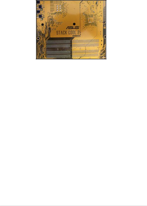
2.2.3ASUS Stack Cool 2
The motherboard comes with the ASUS Stack Cool 2 cooling solution that lowers the temperature of critical heat generating components by 20ºC. The motherboard uses a special design on the printed circuit board (PCB) to dissipate heat that critical components generate.
ASUS P5W64 WS Professional |
2 - 3 |

2.2.4Motherboard layout
|
|
|
|
24.5cm (9.6in) |
|
|
|
|
|
|
|
|
|
|
PS/2KBMS |
|
|
|
|
|
|
|
|
|
|
|
|
|
|
T: Mouse |
|
|
|
|
|
|
|
PWR_FAN |
|
|
|
|||
B: Keyboard |
|
|
|
|
|
|
|
|
|
|
||||
|
|
|
|
|
|
|
|
|
|
|
Super I/O |
|
||
SPDIF_O2 |
PORT |
|
|
|
|
|
|
|
|
|
|
|
|
|
SPDIF_O1 |
|
|
|
|
|
|
|
|
|
|
|
|
|
|
|
|
EATX12V |
|
|
|
CPU_FAN |
|
|
|
|
|
|
|
|
ESATA |
PARALLEL |
|
|
LGA775 |
|
|
PRO |
module) |
module) |
module) |
module) |
|
|
|
LAN1_USB12 |
|
|
|
|
|
WSP5W64® |
bit,240(64A1DIMMDDR2-pin |
bit,240(64A2DIMMDDR2-pin |
bit,240(64B1DIMMDDR2-pin |
bit,240(64B2DIMMDDR2-pin |
PLUGEZ |
FLOPPY EATXPWR |
(12.0in) |
|
|
|
|
|
|
|
|
|
|
|
|
|
|
||
LAN2_USB34 |
|
|
|
|
|
|
|
|
|
|
|
|
|
|
AUDIO |
|
|
|
Intel® |
|
|
|
|
|
|
|
|
|
|
|
|
|
|
|
|
|
|
|
|
|
|
|
|
|
|
|
|
|
|
975X |
|
|
|
|
|
|
|
|
|
|
|
|
|
|
MCH |
|
|
|
|
|
|
|
|
30.5cm |
|
|
CHA_FAN1 |
|
|
|
|
|
|
|
|
|
|
CHA_FAN2 |
|
|
Marvell® |
|
|
|
|
|
|
|
|
|
|
|
|
|
|
88E8052 |
|
|
|
|
|
|
|
|
|
|
|
|
|
|
|
|
|
PCIEX16_1 |
|
|
|
|
|
|
|
|
IDE |
|
|
|
|
|
|
|
|
|
IDT |
|
|
|
|
PRI_ |
|
|
|
|
|
|
|
|
|
|
|
|
|
|
|
|
AD1988B |
|
|
PCIEX16_2 |
|
|
89HA0324 |
|
CR2032 3V |
|
|
|
|||
|
|
|
|
|
|
|
|
|
|
|
|
|
|
|
|
|
|
|
|
|
|
|
|
|
|
Lithium Cell |
|
|
|
|
|
|
|
|
|
|
|
|
|
CMOS Power |
|
|
|
|
|
|
|
|
PCIEX16_3 |
|
|
|
|
|
|
|
|
|
|
|
|
|
|
PCIEX16_4 |
|
|
|
|
Intel® |
|
SATA4 |
SATA3 |
|
|
|
|
|
|
|
|
|
|
ICH7R |
|
|
|
|
||
|
|
|
|
|
|
|
|
|
|
|
|
|
||
|
|
|
|
|
SB_PWR |
|
|
|
|
|
|
|
|
|
® |
88E8001 |
|
|
PCI1 |
TSB43AB22A |
|
|
|
|
|
|
|
|
|
Marvell |
|
|
|
|
|
|
|
|
SATA2 |
SATA1 |
|
|||
|
|
|
|
|
|
|
|
|
|
|
|
|
8Mb |
|
|
|
|
|
PCI2 |
|
|
|
Marvell® |
|
TPM |
|
BIOS |
|
|
|
|
|
|
|
|
|
88SE614x |
|
|
CLRTC |
|
|||
|
|
|
|
|
|
|
|
|
|
|
|
|
||
|
|
COM1 |
|
|
|
|
|
|
|
|
|
|
CHASSIS |
|
CD |
|
USB78 |
USB56 |
IE1394_1 |
IE1394_2 |
EXT_SATA3 |
EXT_SATA2 |
EXT_SATA1 |
|
|
|
|||
|
|
|
|
|
|
|
|
|||||||
AAFP |
|
|
|
|
|
|
|
|
|
|
|
PANEL |
|
|
|
|
|
|
|
|
|
|
|
|
|
|
|
|
|
The Wireless LAN module and the USB port on the module are optional items and are grayed out in the above illustration.
2 - 4 |
Chapter 2: Hardware information |
 Loading...