


P5ND2-SLI
Series
Motherboard

E2167
First Edition
June 2005
Copyright © 2005 ASUSTeK COMPUTER INC. All Rights Reserved.
No part of this manual, including the products and software described in it, may be reproduced, transmitted, transcribed, stored in a retrieval system, or translated into any language in any form or by any means, except documentation kept by the purchaser for backup purposes, without the express written permission of ASUSTeK COMPUTER INC. (ÒASUSÓ).
Product warranty or service will not be extended if: (1) the product is repaired, modified or altered, unless such repair, modification of alteration is authorized in writing by ASUS; or (2) the serial number of the product is defaced or missing.
ASUS PROVIDES THIS MANUAL “AS IS” WITHOUT WARRANTY OF ANY KIND, EITHER EXPRESS OR IMPLIED, INCLUDING BUT NOT LIMITED TO THE IMPLIED WARRANTIES OR CONDITIONS OF MERCHANTABILITY OR FITNESS FOR A PARTICULAR PURPOSE. IN NO EVENT SHALL ASUS, ITS DIRECTORS, OFFICERS, EMPLOYEES OR AGENTS BE LIABLE FOR ANY INDIRECT, SPECIAL, INCIDENTAL, OR CONSEQUENTIAL DAMAGES (INCLUDING DAMAGES FOR LOSS OF PROFITS, LOSS OF BUSINESS, LOSS OF USE OR DATA, INTERRUPTION OF BUSINESS AND THE LIKE), EVEN IF ASUS HAS BEEN ADVISED OF THE POSSIBILITY OF SUCH DAMAGES ARISING FROM ANY DEFECT OR ERROR IN THIS MANUAL OR PRODUCT.
SPECIFICATIONS AND INFORMATION CONTAINED IN THIS MANUAL ARE FURNISHED FOR INFORMATIONAL USE ONLY, AND ARE SUBJECT TO CHANGE AT ANY TIME WITHOUT NOTICE, AND SHOULD NOT BE CONSTRUED AS A COMMITMENT BY ASUS. ASUS ASSUMES NO RESPONSIBILITY OR LIABILITY FOR ANY ERRORS OR INACCURACIES THAT MAY APPEAR IN THIS MANUAL, INCLUDING THE PRODUCTS AND SOFTWARE DESCRIBED IN IT.
Products and corporate names appearing in this manual may or may not be registered trademarks or copyrights of their respective companies, and are used only for identification or explanation and to the owners’ benefit, without intent to infringe.
i i

Contents
Notices ............................................................................................... |
vii |
Safety information ............................................................................ |
viii |
About this guide ................................................................................. |
ix |
How this guide is organized .................................................... |
ix |
Where to find more information .............................................. |
ix |
Conventions used in this guide ................................................ |
x |
Typography .............................................................................. |
x |
P5ND2-SLI Series specifications summary .......................................... |
xi |
Chapter 1: Product introduction
1.1 |
Welcome! .............................................................................. |
1-1 |
|
1.2 |
Package contents ................................................................. |
1-1 |
|
1.3 |
Special features .................................................................... |
1-2 |
|
|
1.3.1 |
Product highlights................................................... |
1-2 |
|
1.3.2 |
ASUS AI features .................................................... |
1-6 |
|
1.3.3 |
Innovative ASUS features ....................................... |
1-7 |
Chapter 2: Hardware information
2.1 |
Before you proceed .............................................................. |
2-1 |
|
2.2 |
Motherboard overview .......................................................... |
2-2 |
|
|
2.2.1 |
Placement direction ................................................ |
2-2 |
|
2.2.2 |
Screw holes ............................................................ |
2-2 |
|
2.2.3 |
Motherboard layout ................................................ |
2-3 |
|
2.2.4 |
Layout contents ..................................................... |
2-4 |
2.3 |
Central Processing Unit (CPU) .............................................. |
2-6 |
|
|
2.3.1 |
Installing the CPU.................................................... |
2-7 |
|
2.3.2 Installing the CPU heatsink and fan ........................ |
2-9 |
|
|
2.3.3 Uninstalling the CPU heatsink and fan .................. |
2-11 |
|
2.4 |
System memory ................................................................. |
2-13 |
|
|
2.4.1 |
Overview ............................................................... |
2-13 |
|
2.4.2 |
Memory configurations ......................................... |
2-14 |
|
2.4.3 |
Installing a DIMM ................................................... |
2-17 |
|
2.4.4 |
Removing a DIMM ................................................. |
2-17 |
2.5 |
Expansion slots ................................................................... |
2-18 |
|
|
2.5.1 Installing an expansion card .................................. |
2-18 |
|
|
2.5.2 Configuring an expansion card.............................. |
2-18 |
|
|
2.5.3 |
Interrupt assignments .......................................... |
2-19 |
i i i

Contents
|
2.5.4 |
PCI slots ................................................................ |
2-20 |
|
2.5.5 PCI Express x1 slot ............................................... |
2-20 |
|
|
2.5.6 Two PCI Express x16 slots ................................... |
2-21 |
|
2.6 |
Jumpers |
.............................................................................. |
2-22 |
2.7 |
Connectors ......................................................................... |
2-24 |
|
|
2.7.1 |
Rear panel connectors .......................................... |
2-24 |
|
2.7.2 |
Internal connectors............................................... |
2-26 |
Chapter 3: Powering up
3.1 |
Starting up for the first time................................................ |
3-1 |
|
3.2 |
Powering off the computer .................................................. |
3-2 |
|
|
3.2.1 Using the OS shut down function ........................... |
3-2 |
|
|
3.2.2 Using the dual function power switch .................... |
3-2 |
|
3.3 |
ASUS POST Reporterª .......................................................... |
3-3 |
|
|
3.3.1 |
Vocal POST messages ............................................ |
3-3 |
|
3.3.2 |
Winbond Voice Editor ............................................. |
3-5 |
Chapter 4: BIOS setup
4.1 Managing and updating your BIOS ........................................ |
4-1 |
||
|
4.1.1 Creating a bootable floppy disk .............................. |
4-1 |
|
|
4.1.2 |
Updating the BIOS .................................................. |
4-2 |
|
4.1.3 Saving the current BIOS file.................................... |
4-4 |
|
|
4.1.4 ASUS CrashFree BIOS 2 utility ................................ |
4-5 |
|
|
4.1.5 ASUS EZ Flash utility .............................................. |
4-7 |
|
|
4.1.6 |
ASUS Update utility ................................................ |
4-8 |
4.2 |
BIOS setup program ........................................................... |
4-11 |
|
|
4.2.1 |
BIOS menu screen................................................. |
4-12 |
|
4.2.2 |
Menu bar ............................................................... |
4-12 |
|
4.2.3 |
Legend bar ........................................................... |
4-13 |
|
4.2.4 |
Menu items ........................................................... |
4-13 |
|
4.2.5 |
Sub-menu items ................................................... |
4-13 |
|
4.2.6 |
Configuration fields .............................................. |
4-13 |
|
4.2.7 |
Pop-up window ..................................................... |
4-14 |
|
4.2.8 |
General help .......................................................... |
4-14 |
4.3 |
Main menu .......................................................................... |
4-15 |
|
|
4.3.1 |
System Time......................................................... |
4-15 |
|
4.3.2 |
System Date ......................................................... |
4-15 |
i v

Contents
|
4.3.3 |
Language .............................................................. |
4-15 |
|
4.3.4 |
Legacy Diskette A ................................................ |
4-15 |
|
4.3.5 |
Primary and Secondary IDE Master/Slave ............. |
4-16 |
|
4.3.6 |
First, Second, Third, Fourth SATA Master ............ |
4-18 |
|
4.3.7 |
HDD SMART Monitoring ........................................ |
4-19 |
|
4.3.8 |
Installed Memory .................................................. |
4-19 |
4.4 |
Advanced menu .................................................................. |
4-20 |
|
|
4.4.1 |
JumperFree Configuration .................................... |
4-21 |
|
4.4.2 |
Speech Configuration ........................................... |
4-26 |
|
4.4.3 |
LAN Cable Status ................................................. |
4-27 |
|
4.4.4 |
PEG Link Mode ...................................................... |
4-28 |
|
4.4.5 |
CPU Configuration................................................. |
4-29 |
|
4.4.6 |
Chipset ................................................................. |
4-30 |
|
4.4.7 |
PCIPnP ................................................................... |
4-32 |
|
4.4.8 |
Onboard Devices Configuration ............................ |
4-32 |
|
4.4.9 |
USB Configuration................................................. |
4-36 |
|
4.4.10 |
SLI Configuration .................................................. |
4-37 |
4.5 |
Power menu ........................................................................ |
4-38 |
|
|
4.5.1 |
ACPI Suspend Type............................................... |
4-38 |
|
4.5.2 |
ACPI APIC Support ................................................ |
4-38 |
|
4.5.3 |
APM Configuration ................................................ |
4-39 |
|
4.5.4 |
Hardware Monitor ................................................. |
4-41 |
4.6 |
Boot menu .......................................................................... |
4-42 |
|
|
4.6.1 |
Boot Device Priority .............................................. |
4-42 |
|
4.6.2 |
Removable Drives ................................................. |
4-45 |
|
4.6.3 |
Hard Disk Drives ................................................... |
4-45 |
|
4.6.4 |
CDROM Drives ....................................................... |
4-46 |
|
4.6.5 |
Boot Settings Configuration ................................. |
4-46 |
|
4.6.6 |
Security ................................................................ |
4-48 |
4.7 |
Exit menu ........................................................................... |
4-50 |
|
Chapter 5: Software support
5.1 |
Installing an operating system ............................................. |
5-1 |
|
5.2 |
Support CD information ........................................................ |
5-1 |
|
|
5.2.1 |
Running the support CD ......................................... |
5-1 |
|
5.2.2 |
Drivers menu .......................................................... |
5-2 |
v

|
5.2.3 |
Utilities menu .......................................................... |
5-3 |
|
5.2.4 |
Make Disk menu ...................................................... |
5-4 |
|
5.2.5 |
Manuals menu ......................................................... |
5-5 |
|
5.2.6 |
ASUS Contact information ...................................... |
5-6 |
|
5.2.7 |
Other information ................................................... |
5-6 |
5.3 |
Software information ........................................................... |
5-9 |
|
|
5.3.1 |
ASUS MyLogo2ª .................................................... |
5-9 |
|
5.3.2 |
AI NET 2 ............................................................... |
5-11 |
|
|
Using the Virtual Cable Testerª ........................... |
5-11 |
|
5.3.3 |
Audio configurations ............................................ |
5-12 |
|
5.3.4 Using the NVIDIA¨ Firewallª ................................. |
5-18 |
|
5.4 |
RAID configurations ............................................................ |
5-21 |
|
|
5.4.1 |
Installing hard disks .............................................. |
5-22 |
|
5.4.2 |
NVIDIA¨ RAID configurations ................................ |
5-23 |
|
5.4.3 Silicon Image RAID configurations ........................ |
5-30 |
|
5.5 Creating a RAID driver disk ................................................. |
5-37 |
||
Chapter 6: NVIDIA¨ SLIª technology support
6.1 |
Overview............................................................................... |
6-1 |
|
Requirements ....................................................................... |
6-1 |
6.2 |
Dual graphics card setup ...................................................... |
6-2 |
|
6.2.1 Setting the ASUS EZ selector card ......................... |
6-2 |
|
6.2.2 Installing SLI-ready graphics cards ......................... |
6-4 |
|
6.2.3 Setting the SLI mode in BIOS ................................. |
6-8 |
|
6.2.4 Installing the device drivers .................................... |
6-8 |
|
6.2.5 Enabling the multi-GPU feature in Windows............ |
6-8 |
Appendix: CPU features
A.1 |
Intel¨ EM64T ........................................................................ |
A-1 |
|
|
Using the Intel¨ EM64T feature ............................................ |
A-1 |
|
A.2 |
Enhanced Intel SpeedStep¨ Technology (EIST) .................... |
A-1 |
|
|
A.2.1 |
System requirements ............................................. |
A-1 |
|
A.2.2 |
Using the EIST ........................................................ |
A-2 |
A.3 |
Intel¨ Hyper-Threading Technology ...................................... |
A-3 |
|
|
Using the Hyper-Threading Technology ............................... |
A-3 |
|
v i

Notices
Federal Communications Commission Statement
This device complies with Part 15 of the FCC Rules. Operation is subject to the following two conditions:
¥This device may not cause harmful interference, and
¥This device must accept any interference received including interference that may cause undesired operation.
This equipment has been tested and found to comply with the limits for a Class B digital device, pursuant to Part 15 of the FCC Rules. These limits are designed to provide reasonable protection against harmful interference in a residential installation. This equipment generates, uses and can radiate radio frequency energy and, if not installed and used in accordance with manufacturerÕs instructions, may cause harmful interference to radio communications. However, there is no guarantee that interference will not occur in a particular installation. If this equipment does cause harmful interference to radio or television reception, which can be determined by turning the equipment off and on, the user is encouraged to try to correct the interference by one or more of the following measures:
¥Reorient or relocate the receiving antenna.
¥Increase the separation between the equipment and receiver.
¥Connect the equipment to an outlet on a circuit different from that to which the receiver is connected.
¥Consult the dealer or an experienced radio/TV technician for help.
The use of shielded cables for connection of the monitor to the graphics card is required to assure compliance with FCC regulations. Changes or modifications to this unit not expressly approved by the party responsible for compliance could void the userÕs authority to operate this equipment.
Canadian Department of Communications Statement
This digital apparatus does not exceed the Class B limits for radio noise emissions from digital apparatus set out in the Radio Interference Regulations of the Canadian Department of Communications.
This class B digital apparatus complies with Canadian ICES-003.
v i i

Safety information
Electrical safety
¥To prevent electrical shock hazard, disconnect the power cable from the electrical outlet before relocating the system.
¥When adding or removing devices to or from the system, ensure that the power cables for the devices are unplugged before the signal cables are connected. If possible, disconnect all power cables from the existing system before you add a device.
¥Before connecting or removing signal cables from the motherboard, ensure that all power cables are unplugged.
¥Seek professional assistance before using an adpater or extension cord. These devices could interrupt the grounding circuit.
¥Make sure that your power supply is set to the correct voltage in your area. If you are not sure about the voltage of the electrical outlet you are using, contact your local power company.
¥If the power supply is broken, do not try to fix it by yourself. Contact a qualified service technician or your retailer.
Operation safety
¥Before installing the motherboard and adding devices on it, carefully read all the manuals that came with the package.
¥Before using the product, make sure all cables are correctly connected and the power cables are not damaged. If you detect any damage, contact your dealer immediately.
¥To avoid short circuits, keep paper clips, screws, and staples away from connectors, slots, sockets and circuitry.
¥Avoid dust, humidity, and temperature extremes. Do not place the product in any area where it may become wet.
¥Place the product on a stable surface.
¥If you encounter technical problems with the product, contact a qualified service technician or your retailer.
viii

About this guide
This user guide contains the information you need when installing and configuring the motherboard.
How this guide is organized
This guide contains the following parts:
¥Chapter 1: Product introduction
This chapter describes the features of the motherboard and the new technology it supports.
¥Chapter 2: Hardware information
This chapter lists the hardware setup procedures that you have to perform when installing system components. It includes description of the switches, jumpers, and connectors on the motherboard.
¥Chapter 3: Powering up
This chapter describes the power up sequence, the vocal POST messages, and ways of shutting down the system.
¥Chapter 4: BIOS setup
This chapter tells how to change system settings through the BIOS Setup menus. Detailed descriptions of the BIOS parameters are also provided.
¥Chapter 5: Software support
This chapter describes the contents of the support CD that comes with the motherboard package.
¥Chapter 6: NVIDIA¨ SLIª technology support
This chapter tells how to install SLI-ready PCI Express graphics cards.
¥Appendix: CPU features
The Appendix describes the CPU features that the motherboard supports.
Where to find more information
Refer to the following sources for additional information and for product and software updates.
1 . ASUS websites
The ASUS website provides updated information on ASUS hardware and software products. Refer to the ASUS contact information.
2 . Optional documentation
Your product package may include optional documentation, such as warranty flyers, that may have been added by your dealer. These documents are not part of the standard package.
i x

Conventions used in this guide
To make sure that you perform certain tasks properly, take note of the following symbols used throughout this manual.
DANGER/WARNING: Information to prevent injury to yourself when trying to complete a task.
CAUTION: Information to prevent damage to the components when trying to complete a task.
IMPORTANT: Instructions that you MUST follow to complete a task.
NOTE: Tips and additional information to help you complete a task.
Typography
Bold text |
Indicates a menu or an item to select. |
Italics |
Used to emphasize a word or a phrase. |
<Key> |
Keys enclosed in the less-than and greater-than |
|
sign means that you must press the enclosed key. |
|
Example: <Enter> means that you must press the |
|
Enter or Return key. |
<Key1+Key2+Key3> |
If you must press two or more keys |
|
simultaneously, the key names are linked with a |
|
plus sign (+). |
|
Example: <Ctrl+Alt+D> |
Command |
Means that you must type the command exactly |
|
as shown, then supply the required item or value |
|
enclosed in brackets. |
|
Example: At the DOS prompt, type the command |
|
line: |
|
afudos /i[filename] |
|
afudos /iP5ND2SLI.ROM |
x
P5ND2-SLI Series specifications summary
C P U
Chipset
Front Side Bus
Memory
Expansion slots
Scalable Link
Interface (SLIª)
AI Audio
LGA775 socket for Intel¨ Pentium¨ Processor Extreme Edition/Intel¨ Pentium¨ D/Intel¨ Pentium¨ 4/
Intel¨ Celeron¨ processors
Compatible with Intel¨ PCG 05B/05A and 04B/04A processors
Supports Intel¨ Enhanced Memory 64 Technology (EM64T) Supports Enhanced Intel SpeedStep¨ Technology (EIST) Supports Intel¨ Hyper-Threading Technology
(N o t e : Due to chipset limitation, the Intel¨ Pentium¨ D 820 processor works only in single-core mode.)
Northbridge: NVIDIA¨ nForceª 4 SLI - Intel¨ Edition
Southbridge: NVIDIA¨ MCP-04
1066/800/533 MHz
Dual-channel memory architecture
4 x 240-pin DIMM sockets support unbufferred non-ECC DDR2-667/DDR2-533 memory modules
Supports up to 8 GB system memory
Supports the NVIDIA¨ Dynamic Adaptive Speculative Preprocessor (DASP) and QuickSync feature
2 x PCI Express x16 slots with Scalable Link Interface (SLIª) support
2 x PCI Express x1 slots
3 x PCI slots
SLIª mode supports:
-2 x identical SLIª-ready PCI Express x16 graphics cards
(N o t e: In SLI mode, the PCI Express x16 slots work at the bandwidth of PCI Express x8. The combined bandwidth of these maintain the bandwidth of PCI Express x16.)
Single card mode supports (default):
-1 x any PCI Express x16 graphics card on the first slot (blue)
-1 x PCI Express x1 card on the second slot (black) ASUS EZ Selector
ASUS SLI Warning LED ASUS EZ Plugª
ASUS PEG Link for dual PCI Express graphics cards ASUS Two-slot thermal design
Realtek¨ ALC850 8-channel CODEC 1 x Coaxial S/PDIF out port
1 x Optical S/PDIF out port
Supports Universal Audio Jack (UAJ¨) Technology Supports Audio Sensing and Enumeration Technology
(continued on the next page)
x i

P5ND2-SLI Series specifications summary
Storage |
NVIDIA¨ nForceª MCP-04 chipset supports: |
|
- 2 x Ultra DMA 133/100/66/33 |
|
- 4 x Serial ATA 3Gb/s devices |
|
- RAID 0, RAID 1, RAID 0+1, RAID 5 and JBOD that |
|
spans across the Serial ATA and Parallel ATA drives |
|
- up to 8 hard disk drives of Multi-RAID configuration |
|
*Silicon Image 3132 SATA controller supports: |
|
- 1 x Internal Serial ATA 3Gb/s hard disk drive |
|
- 1 x External Serial ATA 3Gb/s (SATA On-The-Go) |
|
- RAID 0 and RAID 1 (*Deluxe model only) |
|
|
Dual Gigabit LAN
U S B
IEEE 1394
Overclocking features
Intel¨ 82540EM Gigabit LAN controller
*NVIDIA¨ nForceª 4 - Intel¨ Edition built-in Gigabit MAC with external Marvell¨ PHY supports:
-NV ActiveArmor
-NV Firewall
-AI NET2
(*Deluxe model only)
Supports up to 10 USB 2.0 ports
*TI 1394a controller supports: (*Deluxe model only)
-1 x Internal IEEE 1394a connector
-1 x IEEE 1394a connector at the rear panel
CPU Lock Free
ASUS AI Overclocking (Intelligent Frequency Tuner) ASUS NOS (Non-delay Overclocking System)
ASUS PEG Link for single/dual graphics cards Precision Tweaker supports:
-DIMM voltage: 8-step DRAM voltage control
-Core voltage: Adjustable CPU voltage at 0.0125 V
-PCI Express Frequency: Allows 1MHz increment from 100MHz to 150MHz
-Stepless Frequency Selection(SFS) allows 1MHz
increment from 133MHz to 400 MHz ASUS C.P.R. (CPU Parameter Recall)
Adjustable FSB/DDR2 frequencies with fixed PCI/PCIe frequencies
Special features |
ASUS SATA On-The-Go |
|
ASUS SLI Warning LED |
|
ASUS EZ Plug |
|
ASUS Post Reporterª (Deluxe model only) |
|
ASUS Q-Fan2 (Deluxe model only) |
|
ASUS Q-Fan (non-Deluxe model only) |
|
ASUS CrashFree BIOS 2 |
|
ASUS Multi-language BIOS |
|
ASUS MyLogo2 |
|
ASUS EZ Flash |
|
|
|
(continued on the next page) |
x i i

P5ND2-SLI Series specifications summary
BIOS features
Power
Requirement
Rear panel
Internal connectors
4 MB Flash ROM, Phoenix-Award BIOS, PnP, DMI2.0, SM BIOS 2.3, WfM2.0
ATX power supply (with 24-pin and 4-pin 12 V plugs) ATX 12 V 2.0 compliant
ASUS EZ Plug*
(*When using two graphics cards and a 20-pin ATX PSU)
1 x Parallel port
2 x LAN (RJ-45) ports
4 x USB 2.0 ports
1 x External SATA port (Deluxe model only)
1 x Optical S/PDIF Out port (Deluxe model only)
1 x Coaxial S/PDIF Out port
1 x PS/2 keyboard port (purple)
1 x PS/2 mouse port (green)
1 x IEEE1394a connector (Deluxe model only)
8-channel audio ports
1 x Floppy disk drive connector
2 x IDE connectors
4 x NVIDIA¨ nForceª 4 Serial ATA connectors
1 x Silicon Image SATA connector (Deluxe model only)
1 x Serial port connector (COM port)
1 x 24-pin ATX power connector
1 x 4-pin ATX 12 V power connector 1 x 4-pin ASUS EZ Plugª connector
3 x USB connectors for 6 additional USB 2.0 ports 1 x Internal audio connectors (CD\AUX)
1 x IEEE 1394a connector
1 x GAME/MIDI connector
1 x Chassis intrusion connector
1 x Front panel audio connector
1 x SLI selector card connector
CPU, Chassis (x2), Chipset, Power fan connectors System panel connector
(continued on the next page)
xiii

P5ND2-SLI Series specifications summary
|
Support CD |
Device drivers |
|
contents |
ASUS PC Probe II |
|
|
ASUS Update |
|
|
ASUS AI Booster |
|
|
NV RIS (Remote Installation Service) |
|
|
NV RAID |
|
|
Microsoft¨ DirectX 9.0c |
|
|
Anti-Virus Utility (OEM version) |
|
|
*NV Firewall |
|
|
*WinDVD Suite (OEM version) |
|
|
*Winbond Voice Editor |
|
|
Adobe Acrobat Reader |
|
|
ASUS Screensaver |
|
|
(*Deluxe model only) |
|
|
|
|
Form Factor |
ATX form factor: 12 in x 9.6 in (30.5 cm x 24.4 cm) |
|
|
|
*Specifications are subject to change without notice.
The following are available in the Deluxe model only:
 NVIDIA¨ nForceª 4 - Intel¨ Edition built-in Gigabit MAC with External Marvell¨ PHY support
 TI 1394a IEEE1394 controller
 Silicon Image 3132 SATA controller
 ASUS Post Reporter
 ASUS Q-Fan2
 NV Firewall
 WinDVD Suite
 Winbond Voice Editor
 Optical S/PDIF out
 External SATA port
x i v
This chapter describes the motherboard
features and the new technologies 1 it supports.
Product introduction

Chapter summary |
1 |
1.1 |
Welcome! .............................................................................. |
1-1 |
1.2 |
Package contents ................................................................. |
1-1 |
1.3 |
Special features .................................................................... |
1-2 |
ASUS P5ND2-SLI Series
1.1Welcome!
Thank you for buying an ASUS¨ P5ND2-SLI Series motherboard!
The motherboard delivers a host of new features and latest technologies, making it another standout in the long line of ASUS quality motherboards!
Before you start installing the motherboard, and hardware devices on it, check the items in your package with the list below.
1.2Package contents
Check your motherboard package for the following items.
Motherboard |
|
P5ND2-SLI P5ND2-SLI |
|
|
|||
|
|
Deluxe |
|
|
|
|
|
I/O modules |
IEEE1394a module |
|
Ñ |
|
|
|
|
|
Serial (COM) port module |
|
Ñ |
|
|
|
|
|
USB 2.0 (2 ports) and |
|
|
|
GAME (1 port) module |
|
Ñ |
|
|
|
|
Cables |
5 x Serial ATA cables |
|
Ñ |
|
|
|
|
|
2 x Serial ATA power cables (dual plugs) |
|
Ñ |
|
|
|
|
|
1 x Serial ATA power cable (single plug) |
|
Ñ |
|
|
|
|
|
2 x Serial ATA and power cables |
Ñ |
|
|
|
|
|
|
1 x Ultra DMA 133/100/66 cables |
|
|
|
|
|
|
|
40-conductor IDE cable |
|
|
|
|
|
|
|
Floppy disk drive cable |
|
|
|
|
|
|
Accessories |
I/O shield |
|
|
|
|
|
|
|
1 x EZ Selector card |
|
|
|
|
|
|
|
1 x SLI connector |
|
|
|
|
|
|
|
1 x SLI retention module |
|
|
|
|
|
|
Application CDs |
ASUS motherboard support CD |
|
|
|
|
|
|
|
InterVideo¨ WinDVD Suite¨ (OEM version) |
|
Ñ |
Documentation |
User guide |
|
|
|
|
|
|
If any of the above items is damaged or missing, contact your retailer.
ASUS P5ND2-SLI Series |
1 - 1 |

1.3Special features
1.3.1Product highlights
Latest processor technology 
The motherboard comes with a 775-pin surface mount Land Grid Array (LGA) socket designed for the Intel¨ Pentium¨ Processor Extreme Edition, Intel¨ Pentium¨ D, Intel¨ Pentium¨ 4, and Intel¨ Celeron¨ processor in the 775-land package. The motherboard supports Intel¨ processors with 1066/ 800/533 MHz Front Side Bus (FSB). The motherboard also supports the Intel¨ Hyper-Threading Technology, Intel¨ Dual-Core Technology and is fully compatible with Intel¨ 05B/05A and 04B/04A processors. See page 2-6 for details.
NVIDIA¨ Scalable Link Interface (SLIª) - Intel¨ Edition 
The NVIDIA¨ nForce4¨ Scalable Link Interface (SLIª) - Intel¨ Edition technology allows two graphics processing units (GPUs) in a single system. This technology takes advantage of the PCI Expressª bus architecture and features intelligent hardware and software solutions that allows multiple GPUs to work together and achieve exceptional graphics performance. See Chapter 6 for details.
Intel¨ Dual-Core Technology CPU support 
The motherboard supports dual-core processors containing two physical CPU cores with dedicated L2 caches to meet demands for more powerful processing. See page 2-6 for details.
Intel¨ EM64T 
The motherboard supports Intel¨ processors with the Intel¨ EM64T (Extended Memory 64 Technology). The Intel¨ EM64T feature allows your computer to run on 64-bit operating systems and access larger amounts of system memory for faster and more efficient computing. See the Appendix for details.
Enhanced Intel SpeedStep¨ Technology (EIST)
The Enhanced Intel SpeedStep¨ Technology (EIST) intelligently manages the CPU resources by automatically adjusting the CPU voltage and core frequency depending on the CPU loading and system speed or power requirement. See Appendix for details.
1 - 2 |
Chapter 1: Product introduction |

DDR2 memory support 


The motherboard supports DDR2 memory which features data transfer rates of 667 MHz or 533 MHz to meet the higher bandwidth requirements of the latest 3D graphics, multimedia, and Internet applications. The dual-channel DDR2 architecture doubles the bandwidth of your system memory to boost system performance, eliminating bottlenecks with peak bandwidths of up to 10.7 GB/s. See pages 2-13 to 2-16 for details.
NVIDIA¨ QuickSync
The NVIDIA¨ nForce4¨ SLIª - Intel¨ Edition memory controller features the QuickSynch synchronization technology that transfers memory requests and data between the Front Side Bus (FSB) and memory clock domains in the shortest amount of time. QuickSync ensures that the memory controller has the shortest latency between receiving/placing CPU requests, and between receiving the data from memory and sending it to the CPU for all FSB and memory speeds.
NVIDIA¨ DASP 3.0
The NVIDIA¨ Dynamic Adaptive Speculative Preprocessor (DASP) 3.0 comes with sophisticated data pre-fetch algorithms in preprocessors that are tasked to track data threads and pre-fetch appropriate data for improved performance.
Built-in NVFirewallª and NVActiveArmorª
The NVIDIA¨ Firewallª (NVFirewallª) is an easy-to-use high-performance desktop firewall application that protects your system from intruders. Integrated into the NVIDIA¨ nForce4¨ SLIª chipset, it provides advanced anti-computer-hacking technologies, remote management capabilities, and a user-friendly setup wizard that improves overall system security.
Enhancing your network security is the NVIDIA¨ ActiveArmorª
(NV ActiveArmorª) engine that provides advanced data packet inspection. This innovative technology ensures that only safe data packets are passed on the network. It boosts overall system performance by offloading the CPU from the rigorous task of filtering data packets. See page 5-18 for details.
ASUS P5ND2-SLI Series |
1 - 3 |

Serial ATA 3Gb/s and SATA-On-The-Go 
The motherboard supports the Serial ATA 3 Gb/s technology through the Silicon Image Serial ATA interfaces and the NVIDIA¨ SLIª - Intel¨ Edition chipset. The Serial ATA 3 Gb/s specification provides twice the bandwidth of the current Serial ATA products with a host of new features, including Native Command Queuing (NCQ), Power Management (PM) Implementation Algorithm, and Hot Swap. Serial ATA allows thinner, more flexible cables with lower pin count and reduced voltage requirements.
Leveraging these Serial ATA 3Gb/s features is the *SATA-On-The-Go. This external port on the rear panel I/O provides smart setup, hot-plug and support for up to 16 devices with port-multiplier functions. See pages 2-28 and 2-29 for details. (*Deluxe model only)
Dual RAID solution
Onboard RAID controllers provide the motherboard with dual-RAID functionality that allows you to select the best RAID solution using IDE or Serial ATA devices.
The NVIDIA¨ nForce4¨ SLIª allows RAID 0, RAID 1, RAID 0+1, JBOD, and a software patch to support RAID 5 configuration for four SATA 3Gb/s and two PATA connectors. See pages 2-27 and 5-23.
The *Sil3132R controller supports two additional SATA 3Gb/s connectors and allows RAID 0 and RAID 1 configurations through the internal and external SATA ports. See pages 2-28 and 5-30 for details.
(*Deluxe model only)
Dual Gigabit LAN solution (Deluxe model only)
The motherboard comes with dual Gigabit LAN controllers to provide the total solution for your networking needs. These network controllers use the PCI Express segment to provide faster data bandwidth for your wired or wireless Internet, LAN, and file sharing requirements. See page 2-25 for details.
PCI Expressª interface
The motherboard fully supports PCI Express, the latest I/O interconnect technology that speeds up the PCI bus. PCI Express features point-to-point serial interconnections between devices and allows higher clockspeeds by carrying data in packets. This high speed interface is software compatible with existing PCI specifications. See pages 2-20 and 2-21 for details.
1 - 4 |
Chapter 1: Product introduction |
CPU Lock Free
This feature allows you to adjust the CPU multiplier to 14x. Setting the appropriate BIOS setting automatically reduces the CPU multiplier value for more flexibility when increasing external FSB. See page 4-29 for details.
S/PDIF digital sound ready 
The motherboard supports the S/PDIF technology through the S/PDIF interfaces on the rear panel and at midboard. The S/PDIF technology turns your computer into a high-end entertainment system with digital connectivity to powerful audio and speaker systems. See page 2-26 for details.
IEEE 1394a support  (Deluxe model only)
The IEEE 1394a interface provides high-speed and flexible PC connectivity to a wide range of peripherals and devices compliant to the IEEE 1394a standard. The IEEE 1394a interface allows up to 400 Mbps transfer rates through simple, low-cost, high-bandwidth asynchronous (real-time) data interfacing between computers, peripherals, and consumer electronic devices such as camcorders, VCRs, printers, TVs, and digital cameras. See pages 2-25 and 2-31 for details.
USB 2.0 technology 
The motherboard implements the Universal Serial Bus (USB) 2.0 specification, dramatically increasing the connection speed from the
12 Mbps bandwidth on USB 1.1 to a fast 480 Mbps on USB 2.0. USB 2.0 is backward compatible with USB 1.1. See pages 2-25 and 2-31 for details.
ASUS P5ND2-SLI Series |
1 - 5 |

1.3.2ASUS AI features
AI Quiet 
The ASUS AI Quiet function dynamically controls CPU speed and reduces temperature and fan speeds, thus minimizing noise and ensuring quiet operation. Enable ASUS Q-Fan and install an Intel¨ processor with Enhanced Intel SpeedStep Technology (EIST) to use this feature.
AI NOSª (Non-Delay Overclocking System) 
ASUS Non-delay Overclocking Systemª (NOS) is a technology that auto-detects the CPU loading and dynamically overclocks the CPU speed only when needed. See page 4-22 for details.
Precision Tweaker
This feature allows you to fine tune the CPU/memory voltage and gradually increase the memory Front Side Bus (FSB) and PCI Express frequency at 1MHz increment to achieve maximum system performance.
AI NET 2  (Deluxe model only)
AI NET 2 is a BIOS-based diagnostic tool that detects and reports Ethernet cable faults and shorts. With this utility, you can easily monitor the condition of the Ethernet cable(s) connected to the Marvell LAN (RJ-45) port. During the bootup process, AI NET 2 immediately diagnoses the LAN cable and reports shorts and faults up to 100 meters at 1 meter accuracy. See pages 2-25 and 5-11 for details.
AI Audio technology 

The motherboard supports 8-channel audio through the onboard Realtek¨ ALC850 CODEC with 16-bit DAC, a stereo 16-bit ADC, and an AC97 2.3 compatible multi-channel audio designed for PC multimedia systems. It also provides Jack-Sensing function, S/PDIF out support, interrupt capability and includes the Realtek¨ proprietary UAJ¨ (Universal Audio Jack) technology. See pages 2-24 and 5-12 for details.
Fanless Design
The ASUS fanless design allows multi-directional heat flow from major thermal sources in the motherboard to lower overall system temperature, resulting in quieter operation and longer system life.
1 - 6 |
Chapter 1: Product introduction |

PEG Link Mode for two graphics cards
This feature enhances your PCI Express graphics card performance. It allows the motherboard to automatically adjust the PCI Express graphics link mode to the correct frequency based on the system configuration. Four additional settings are available for overclocking the PEG Link Mode. See page 4-28 for details.
1.3.3Innovative ASUS features
ASUS Two-slot thermal design
The motherboard is designed with two PCI Express x1 slots placed between the PCI Express x16 slots allowing an increase in airflow between the two PCI Express x16 graphics cards. This special design permits more room for ventilation thus lowering the overall system temperature.
CrashFree BIOS 2 
This feature allows you to restore the original BIOS data from the support CD in case when the BIOS codes and data are corrupted. This protection eliminates the need to buy a replacement ROM chip. See page 4-5 for details.
ASUS Q-Fan 2 technology  (Deluxe model only)
The ASUS Q-Fan 2 technology smartly adjusts the CPU and chassis fan 1 speeds according to the system loading to ensure quiet, cool, and efficient operation. See page 4-41 for details.
ASUS Multi-language BIOS 
The multi-language BIOS allows you to select the language of your choice from the available options. The localized BIOS menus allow easier and faster configuration. See page 4-15 for details.
ASUS POST Reporterª  (Deluxe model only)
The motherboard offers a new exciting feature called the ASUS POST Reporterª. The ASUS POST Reporterª provides friendly voice messages and alerts during the Power-On Self-Tests (POST) to inform you of the system boot status and causes of boot errors, if any. The bundled Winbond Voice Editor software lets you to customize the voice messages in different languages. See page 3-3 for details.
ASUS P5ND2-SLI Series |
1 - 7 |

ASUS MyLogo2ª 
This new feature present in the motherboard allows you to personalize and add style to your system with customizable boot logos. See page 5-9 for details.
ASUS EZ Plugª
This patented ASUS technology is a 4-pin auxiliary +12V connector that is designed to maintain the voltage integrity of your system. This plug guarantees adequate supply of power to the motherboard and other installed peripherals. See page 2-34 for the illustration.
C.P.R. (CPU Parameter Recall)
The C.P.R. feature of the motherboard BIOS allows automatic re-setting to the BIOS default settings in case the system hangs due to overclocking. When the system hangs due to overclocking, C.P.R. eliminates the need to open the system chassis and clear the RTC data. Simply shut down and reboot the system, and the BIOS automatically restores the CPU default setting for each parameter.
1 - 8 |
Chapter 1: Product introduction |
This chapter lists the hardware setup procedures that you have to perform when installing system components. It includes description of the jumpers and connectors on the motherboard.
Hardware2 information

Chapter summary |
2 |
2.1 |
Before you proceed .............................................................. |
2-1 |
2.2 |
Motherboard overview .......................................................... |
2-2 |
2.3 |
Central Processing Unit (CPU) .............................................. |
2-6 |
2.4 |
System memory ................................................................. |
2-13 |
2.5 |
Expansion slots ................................................................... |
2-18 |
2.6 |
Jumpers .............................................................................. |
2-22 |
2.7 |
Connectors ......................................................................... |
2-24 |
ASUS P5ND2-SLI Series
2.1Before you proceed
Take note of the following precautions before you install motherboard components or change any motherboard settings.
¥ Unplug the power cord from the wall socket before touching any component.
¥Use a grounded wrist strap or touch a safely grounded object or to a metal object, such as the power supply case, before handling components to avoid damaging them due to static electricity.
¥Hold components by the edges to avoid touching the ICs on them.
¥Whenever you uninstall any component, place it on a grounded antistatic pad or in the bag that came with the component.
¥Before you install or remove any component, ensure that the ATX power supply is switched off or the power cord is detached from the power supply. Failure to do so may cause severe damage to the motherboard, peripherals, and/or components.
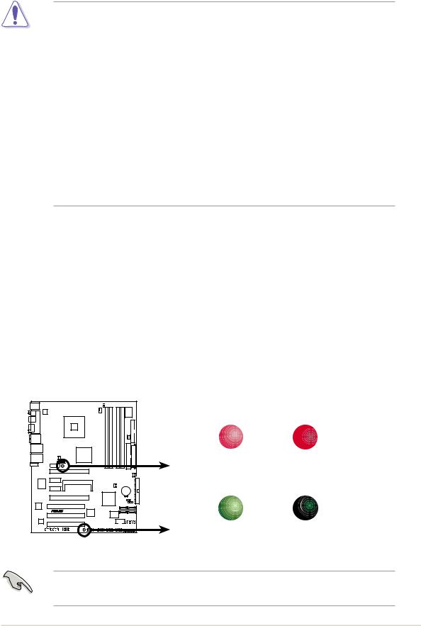
Onboard LED
The motherboard comes with a standby power LED. The green LED lights up to indicate that the system is ON, in sleep mode, or in softoff mode. This is a reminder that you should shut down the system and unplug the power cable before removing or plugging in any motherboard component. The illustration below shows the location of the onboard LED.
The red warning LED lights up when you installed two graphics card but did not connect the ASUS EZ Plugª. The illustration below shows the location of the onboard LEDs.
|
WARN_LED |
|
P5ND2-SLI |
|
|
|
ON |
OFF |
|
When use 2 Graphics |
When use 2 Graphics |
|
but do not plug EZ-PLUG |
but do plug EZ-PLUG |
|
SB_PWR |
|
|
ON |
OFF |
P5ND2-SLI Series Onboard LED |
Standby |
Powered |
Power |
Off |
|
Make sure to connect the EZPlug when using two PCI Express graphics cards and a 20-pin ATX power supply unit.
ASUS P5ND2-SLI Series |
2 - 1 |
2.2Motherboard overview
Before you install the motherboard, study the configuration of your chassis to ensure that the motherboard fits into it.
Make sure to unplug the power cord before installing or removing the motherboard. Failure to do so can cause you physical injury and damage motherboard components.
2.2.1Placement direction
When installing the motherboard, make sure that you place it into the chassis in the correct orientation. The edge with external ports goes to the rear part of the chassis as indicated in the image below.
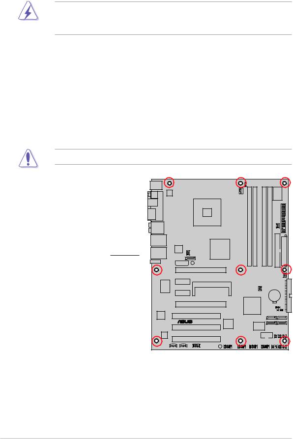
2.2.2Screw holes
Place nine (9) screws into the holes indicated by circles to secure the motherboard to the chassis.
Do not overtighten the screws! Doing so can damage the motherboard.
Place this side towards the rear of the chassis
P5ND2-SLI |
CR2032 3V |
Lithium Cell |
CMOS Power |
® |
2 - 2 |
Chapter 2: Hardware information |

2.2.3Motherboard layout
|
|
|
24.5cm (9.6in) |
||||||||
|
|
|
|
|
|
|
|
|
|
|
|
|
|
|
|
|
|
|
|
|
|
|
|
|
|
|
|
|
|
FANSEL |
|||||
PS/2KBMS |
|
|
|
||||||||
|
|
|
|||||||||
T: Mouse |
|
|
|
|
|
|
|
|
|
||
|
|
|
|
|
|
|
|
|
|||
B: Keyboard |
|
|
|
|
|
|
|
|
|
||
|
|
|
|
|
|
|
|
|
|||
|
|
|
|
|
|
|
|
|
|
|
|
|
SPDIF_O |
|
|
|
|
CPU_FAN |
|
|
|
|
Super I/O |
|
|
|
|
|
|
|
|
|
|
|
|
||
|
|
|
ATX12V |
|
|
|
|
|
|
|
|
|
|
|
PORTPARALLEL |
|
|
|
|
|
|
|
|
|
|
|
ESATA |
|
|
LGA775 |
|
module) |
module) |
module) |
module) |
|
|
|
|
SPDIF_O2 |
|
|
|
|
|
(64A1DIMMbit,240-pin |
(64A2DIMMbit,240-pin |
(64B1DIMMbit,240-pin |
(64B2DIMMbit,184-pin |
|
|
|
AUDIO |
|
|
|
P5ND2-SLI |
CHA FAN1 |
FLOPPY |
|||||
|
|
|
|
|
|
|
|
|
|
|
||
Intel LAN |
LAN2_USB34 |
|
|
|
DDR2 |
DDR2 |
DDR2 |
DDR2 |
EATXPWR |
|
||
|
|
|
|
Silicon |
nVidia nForce4 SLI |
|
|
|||||
Marvell LAN |
|
|
|
Image |
Intel Edition |
|
|
|
|
|
|
|
LAN1_USB12 |
|
|
NB_FAN |
|
|
|
|
|
|
|
||
|
|
|
|
|
|
|
|
|
|
|
||
|
|
|
SATA_RAID2 |
|
|
|
|
|
IDE |
|
|
|
|
E1394 |
|
EZ_PLUG |
WARN_LED |
|
|
|
|
|
|
||
|
|
|
|
|
|
|
|
SEC |
|
|
||
|
|
|
|
|
PCIEX16_1 |
|
|
|
|
|
|
|
|
|
|
|
|
|
|
|
|
|
|
|
|
|
|
Marvell |
88E1111 |
|
|
|
|
|
|
PWR_FAN |
IDEPRI |
|
|
|
PCIEX1_1 |
SLI_CON |
|
|
|
|
|
|
|||
|
|
|
|
|
|
|
|
|
|
|
||
|
|
|
|
|
|
|
|
|
|
|
|
|
|
|
|
|
PCIEX1_2 |
|
|
|
CHA_FAN2 |
CR2032 3V |
|
||
|
|
|
|
|
|
|
|
|
|
Lithium Cell |
|
|
|
|
|
|
|
|
|
|
|
|
CMOS Power |
|
|
|
|
|
|
|
PCIEX16_2 |
|
MCP-04 |
|
|
|
|
|
|
|
|
|
|
|
|
|
CLRTC |
|
|
||
|
|
|
|
|
|
|
|
|
|
|
|
|
|
|
|
|
|
|
|
|
|
|
CHASSIS |
|
|
|
|
intel |
|
|
PCI1 |
|
|
|
|
SATA1 |
SATA2 |
|
|
|
82540EM |
|
|
|
|
|
|
|
|||
|
|
|
|
|
|
|
|
|
|
|
||
|
|
|
|
|
® |
|
|
|
|
|
|
|
|
|
|
|
|
TSB43AB22A |
|
|
4Mb |
SATA4 |
SATA3 |
|
|
|
|
|
|
|
PCI2 |
|
|
|
||||
|
|
|
|
|
|
|
BIOS |
|
|
|
||
|
|
ACL850 |
|
|
|
|
|
|
|
GAME |
||
|
|
|
|
|
|
COM1 |
|
|
|
|
||
|
|
|
|
|
PCI3 |
|
|
|
|
|
|
|
|
|
|
|
|
|
|
|
|
|
|
|
|
|
|
|
|
|
IE_1394_1 |
USB56 |
USB78 |
USB910 |
PANEL |
|
||
|
|
|
|
|
SB_PWR |
|
|
|
|
|
|
|
|
|
|
CD |
AUX |
FP_AUDIO |
|
|
|
|
|
|
|
30.5cm (12.0in)
The Silicon Image Sil3132 chip, SATA_RAID2, External SATA port, IEEE 1394 connector, IEEE 1394 port, Marvell LAN, and Marvell LAN port are available in the Deluxe model only. These components are grayed out on the given motherboard layout.
ASUS P5ND2-SLI Series |
2 - 3 |

2.2.4Layout contents
S l o t s P a g e
|
1. |
DDR2 DIMM slots |
2-13 |
|
2. |
PCI slots |
2-20 |
|
|
|
|
|
3. |
PCI Express x1 slot |
2-20 |
|
|
|
|
|
4. |
PCI Express x16 slot |
2-21 |
|
|
|
|
|
|
|
|
|
Jumpers |
P a g e |
|
|
1. |
Clear RTC RAM (3-pin CLRTC) |
2-22 |
|
|
|
|
|
2. |
Fan selector (3-pin FANSEL) |
2-23 |
|
|
|
|
|
|
|
|
|
Rear panel connectors |
P a g e |
|
|
1. |
PS/2 mouse port (green) |
2-24 |
|
2. |
Parallel port |
2-24 |
|
3. |
Rear Speaker Out port (gray) |
2-24 |
|
4. |
Side Speaker Out port (black) |
2-24 |
|
5. |
Center/Subwoofer port (yellow orange) |
2-24 |
|
6. |
Line In port (light blue) |
2-24 |
|
7. |
Line Out port (lime) |
2-24 |
|
8. |
Microphone port (pink) |
2-24 |
|
9. |
LAN 2 (RJ-45) [Intel¨] |
2-25 |
|
10. |
LAN 1 (RJ-45) [Marvell¨] (Deluxe model only) |
2-25 |
|
11. |
IEEE 1394 port (Deluxe model only) |
2-25 |
|
12. |
USB 2.0 ports 3 and 4 |
2-25 |
|
13. |
USB 2.0 ports 1 and 2 |
2-25 |
|
14. |
External SATA port (Deluxe model only) |
2-26 |
|
14. |
Optical S/PDIF Out port (Deluxe model only) |
2-26 |
|
15. |
Coaxial S/PDIF Out port |
2-26 |
|
16. |
PS/2 keyboard port (purple) |
2-26 |
|
|
|
|
2 - 4 |
Chapter 2: Hardware information |
 Loading...