


P5GD1-VM

P5GD1-VM
Motherboard

E1671E1671
E1671
E1671E1671
First EditionFirst Edition
First Edition
First EditionFirst Edition
June 2004June 2004
June 2004
June 2004June 2004
Copyright © 2004 ASUSTeK COMPUTER INC. All Rights Reserved.
No part of this manual, including the products and software described in it, may be reproduced,
transmitted, transcribed, stored in a retrieval system, or translated into any language in any form
or by any means, except documentation kept by the purchaser for backup purposes, without the
express written permission of ASUSTeK COMPUTER INC. (“ASUS”).
Product warranty or service will not be extended if: (1) the product is repaired, modified or
altered, unless such repair, modification of alteration is authorized in writing by ASUS; or (2)
the serial number of the product is defaced or missing.
ASUS PROVIDES THIS MANUAL “AS IS” WITHOUT WARRANTY OF ANY KIND, EITHER
EXPRESS OR IMPLIED, INCLUDING BUT NOT LIMITED TO THE IMPLIED WARRANTIES
OR CONDITIONS OF MERCHANTABILITY OR FITNESS FOR A PARTICULAR PURPOSE.
IN NO EVENT SHALL ASUS, ITS DIRECTORS, OFFICERS, EMPLOYEES OR AGENTS BE
LIABLE FOR ANY INDIRECT, SPECIAL, INCIDENTAL, OR CONSEQUENTIAL DAMAGES
(INCLUDING DAMAGES FOR LOSS OF PROFITS, LOSS OF BUSINESS, LOSS OF USE
OR DATA, INTERRUPTION OF BUSINESS AND THE LIKE), EVEN IF ASUS HAS BEEN
ADVISED OF THE POSSIBILITY OF SUCH DAMAGES ARISING FROM ANY DEFECT OR
ERROR IN THIS MANUAL OR PRODUCT.
SPECIFICATIONS AND INFORMATION CONTAINED IN THIS MANUAL ARE FURNISHED
FOR INFORMATIONAL USE ONLY, AND ARE SUBJECT TO CHANGE AT ANY TIME
WITHOUT NOTICE, AND SHOULD NOT BE CONSTRUED AS A COMMITMENT BY ASUS.
ASUS ASSUMES NO RESPONSIBILITY OR LIABILITY FOR ANY ERRORS OR
INACCURACIES THAT MAY APPEAR IN THIS MANUAL, INCLUDING THE PRODUCTS
AND SOFTWARE DESCRIBED IN IT.
Products and corporate names appearing in this manual may or may not be registered
trademarks or copyrights of their respective companies, and are used only for identification or
explanation and to the owners’ benefit, without intent to infringe.
iiii
ii
iiii

Contents
Notices ............................................................................................ 1-vi
Safety information .......................................................................... 1-vii
Operation safety ............................................................................. 1-vii
P5GD1-VM specifications summary ............................................... 1-viii
Chapter 1:Chapter 1:
Chapter 1:
Chapter 1:Chapter 1:
1.1 Welcome! .............................................................................. 1-2
1.2 Package contents ................................................................. 1-2
1.3 Special features .................................................................... 1-2
1.3.1 Product highlights................................................... 1-2
1.3.2 Innovative ASUS features ....................................... 1-4
1.4 Before you proceed .............................................................. 1-5
1.5 Motherboard overview .......................................................... 1-6
1.5.1 Motherboard layout ................................................ 1-6
1.5.2 Placement direction ................................................ 1-7
1.5.3 Screw holes ............................................................ 1-7
16.1 Installling the CPU ................................................... 1-8
1.6 Central Processing Unit (CPU) .............................................. 1-8
1.6.2 Installling the CPU heatsink and fan ..................... 1-11
1.7 System memory ................................................................. 1-13
1.7.1 DIMM sockets location .......................................... 1-13
Product introductionProduct introduction
Product introduction
Product introductionProduct introduction
1.7.2 Memory Configurations .........................................1-14
1.7.3 Installing a DIMM ................................................... 1-16
1.7.4 Removing a DIMM ................................................. 1-16
1.8 Expansion slots ................................................................... 1-17
1.8.1 Installing an expansion card .................................. 1-17
1.8.2 Configuring an expansion card.............................. 1-17
1.8.3 PCI slots ................................................................ 1-19
1.8.4 PCI Express x16 slot .............................................1-19
1.8.5 PCI Express x1 slot ...............................................1-19
1.9 Jumpers .............................................................................. 1-20
1.10 Connectors ......................................................................... 1-22
1.10.1 Rear panel connectors .......................................... 1-22
1.10.2 Internal connectors............................................... 1-24
iiiiii
iii
iiiiii

Contents
Chapter 2:Chapter 2:
Chapter 2:
Chapter 2:Chapter 2:
2.1 Managing and updating your BIOS ........................................ 2-2
2.1.1 Creating a bootable floppy disk .............................. 2-2
2.1.2 AFUDOS utility ........................................................ 2-3
2.1.3 ASUS EZ Flash utility .............................................. 2-5
2.1.4 ASUS CrashFree BIOS 2 utility ................................ 2-7
2.1.5 ASUS Update utility ................................................ 2-9
2.2 BIOS setup program ........................................................... 2-12
2.2.1 BIOS menu screen ................................................. 2-13
2.2.2 Menu bar ............................................................... 2-13
2.2.3 Navigation keys .................................................... 2-13
2.2.4 Menu items ........................................................... 2-14
2.2.5 Sub-menu items ................................................... 2-14
2.2.6 Configuration fields .............................................. 2-14
2.2.7 Pop-up window ..................................................... 2-14
2.2.8 Scroll bar .............................................................. 2-14
BIOS setupBIOS setup
BIOS setup
BIOS setupBIOS setup
2.2.9 General help .......................................................... 2-14
2.3 Main menu .......................................................................... 2-15
2.3.1 System Time ......................................................... 2-15
2.3.2 System Date ......................................................... 2-15
2.3.3 Legacy Diskette A ................................................ 2-15
2.3.4 Primary, Third, and Fourth IDE Master/Slave ........ 2-16
2.3.5 IDE Configuration .................................................. 2-17
2.3.6 System Information .............................................. 2-18
2.4 Advanced menu .................................................................. 2-19
2.4.1 USB Configuration................................................. 2-19
2.4.2 CPU Configuration ................................................. 2-20
2.4.3 Chipset ................................................................. 2-21
2.4.4 Onboard Devices Configuration ............................ 2-23
2.4.5 PCI PnP ................................................................. 2-24
2.5 Power menu ........................................................................ 2-26
2.5.1 Suspend Mode ...................................................... 2-26
iviv
iv
iviv
2.5.2 Repost Video on S3 Resume ................................ 2-26
2.5.3 ACPI 2.0 Support .................................................. 2-26

Contents
2.5.4 ACPI APIC Support ................................................ 2-26
2.5.5 APM Configuration ................................................ 2-27
2.5.6 Hardware Monitor ................................................. 2-28
2.6 Boot menu .......................................................................... 2-30
2.6.1 Boot Device Priority .............................................. 2-30
2.6.2 Boot Settings Configuration ................................. 2-31
2.6.3 Security ................................................................ 2-32
2.7 Exit menu ........................................................................... 2-34
Chapter 3:Chapter 3:
Chapter 3:
Chapter 3:Chapter 3:
3.1 Installing an operating system ............................................. 3-2
3.2 Support CD information ........................................................ 3-2
3.2.1 Running the support CD ......................................... 3-2
3.2.2 Drivers menu .......................................................... 3-3
3.2.3 Utilities menu .......................................................... 3-4
3.2.4 ASUS Contact information ...................................... 3-5
3.2.5 Other information ................................................... 3-6
Software supportSoftware support
Software support
Software supportSoftware support
vv
v
vv
Notices
Federal Communications Commission StatementFederal Communications Commission Statement
Federal Communications Commission Statement
Federal Communications Commission StatementFederal Communications Commission Statement
This device complies with Part 15 of the FCC Rules. Operation is subject to
the following two conditions:
•
This device may not cause harmful interference, and
•
This device must accept any interference received including interference
that may cause undesired operation.
This equipment has been tested and found to comply with the limits for a
Class B digital device, pursuant to Part 15 of the FCC Rules. These limits are
designed to provide reasonable protection against harmful interference in a
residential installation. This equipment generates, uses and can radiate radio
frequency energy and, if not installed and used in accordance with
manufacturer’s instructions, may cause harmful interference to radio
communications. However, there is no guarantee that interference will not
occur in a particular installation. If this equipment does cause harmful
interference to radio or television reception, which can be determined by
turning the equipment off and on, the user is encouraged to try to correct
the interference by one or more of the following measures:
•
Reorient or relocate the receiving antenna.
•
Increase the separation between the equipment and receiver.
•
Connect the equipment to an outlet on a circuit different from that to
which the receiver is connected.
•
Consult the dealer or an experienced radio/TV technician for help.
The use of shielded cables for connection of the monitor to the graphics
card is required to assure compliance with FCC regulations. Changes or
modifications to this unit not expressly approved by the party
responsible for compliance could void the user’s authority to operate
this equipment.
Canadian Department of Communications StatementCanadian Department of Communications Statement
Canadian Department of Communications Statement
Canadian Department of Communications StatementCanadian Department of Communications Statement
This digital apparatus does not exceed the Class B limits for radio noise
emissions from digital apparatus set out in the Radio Interference
Regulations of the Canadian Department of Communications.
This class B digital apparatus complies with CanadianThis class B digital apparatus complies with Canadian
This class B digital apparatus complies with Canadian
This class B digital apparatus complies with CanadianThis class B digital apparatus complies with Canadian
ICES-003.ICES-003.
ICES-003.
ICES-003.ICES-003.
vivi
vi
vivi

Safety information
Electrical safetyElectrical safety
Electrical safety
Electrical safetyElectrical safety
•
To prevent electrical shock hazard, disconnect the power cable from
the electrical outlet before relocating the system.
•
When adding or removing devices to or from the system, ensure that
the power cables for the devices are unplugged before the signal cables
are connected. If possible, disconnect all power cables from the existing
system before you add a device.
•
Before connecting or removing signal cables from the motherboard,
ensure that all power cables are unplugged.
•
Seek professional assistance before using an adapter or extension cord.
These devices could interrupt the grounding circuit.
•
Make sure that your power supply is set to the correct voltage in your
area. If you are not sure about the voltage of the electrical outlet you
are using, contact your local power company.
•
If the power supply is broken, do not try to fix it by yourself. Contact a
qualified service technician or your retailer.
Operation safety
•
Before installing the motherboard and adding devices on it, carefully read
all the manuals that came with the package.
•
Before using the product, make sure all cables are correctly connected
and the power cables are not damaged. If you detect any damage,
contact your dealer immediately.
•
To avoid short circuits, keep paper clips, screws, and staples away from
connectors, slots, sockets and circuitry.
•
Avoid dust, humidity, and temperature extremes. Do not place the
product in any area where it may become wet.
•
Place the product on a stable surface.
•
If you encounter technical problems with the product, contact a qualified
service technician or your retailer.
viivii
vii
viivii
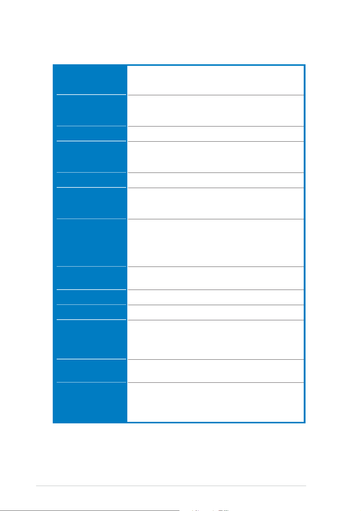
P5GD1-VM specifications summary
CPUCPU
CPU
CPUCPU
LGA775 socket for Intel® Pentium® 4/Celeron processor
Compatible with Intel® PCG 04A and 04B processors
Supports Intel® Hyper-Threading Technology
ChipsetChipset
Chipset
ChipsetChipset
Front Side BusFront Side Bus
Front Side Bus
Front Side BusFront Side Bus
MemoryMemory
Memory
MemoryMemory
GraphicsGraphics
Graphics
GraphicsGraphics
Expansion slotsExpansion slots
Expansion slots
Expansion slotsExpansion slots
StorageStorage
Storage
StorageStorage
High DefinitionHigh Definition
High Definition
High DefinitionHigh Definition
AudioAudio
Audio
AudioAudio
Northbridge: Intel
®
915G Graphics Memory Controller
Hub (GMCH)
Southbridge: Intel® ICH6
800/533 MHz
Dual-channel memory architecture
4 x 184-pin DIMM sockets support unbufferred non-ECC
400/333 MHz DDR memory modules
Integrated Intel® Graphics Media Accelerator 900
1 x PCI Express x16 slot for discrete graphics card
1 x PCI Express x1 slot
2 x PCI slots
®
ICH6 Southbridge supports:
Intel
- 1 x Single-channel Ultra DMA 100/66/33
- 4 x Serial ATA
ITE® 8211F IDE controller supports:
- 1 x Single-channel Ultra DMA 133/100
Realtek
®
ALC861 8-channel CODEC
S/PDIF out interface support
LANLAN
LAN
LANLAN
USBUSB
USB
USBUSB
Special featuresSpecial features
Special features
Special featuresSpecial features
BIOS featuresBIOS features
BIOS features
BIOS featuresBIOS features
AccessoriesAccessories
Accessories
AccessoriesAccessories
Intel® 10/100 Fast Ethernet LAN controller
Supports up to 8 USB 2.0 ports
ASUS CrashFree BIOS 2
ASUS Q-Fan
ASUS EZ Flash
ASUS MyLogo
4 MB Flash ROM, AMI BIOS, PnP, DMI2.0, SM BIOS 2.3,
WfM2.0
2 x Serial ATA signal cables
1 x Ultra DMA 133/100/66 cable
1 x FDD cable
1 x I/O shield
(continued on the next page)
viiiviii
viii
viiiviii
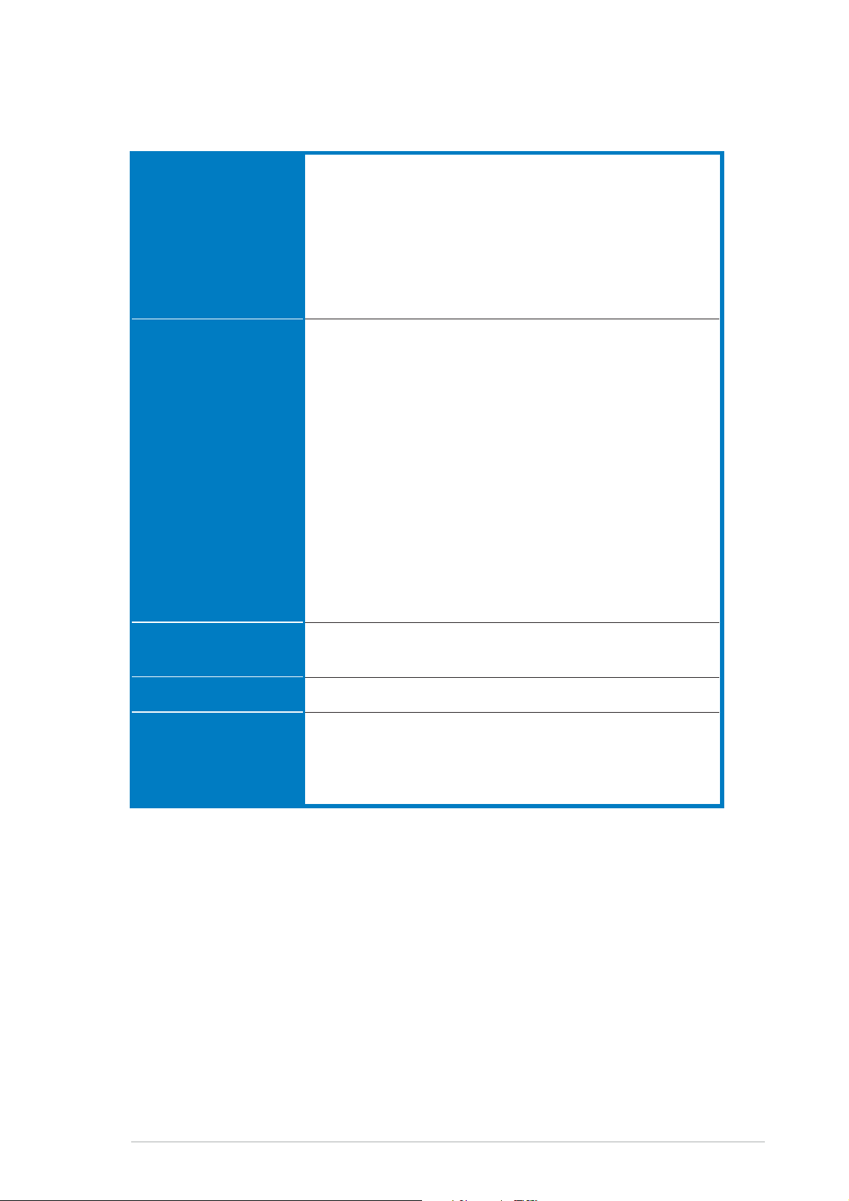
P5GD1-VM specifications summary
Rear panelRear panel
Rear panel
Rear panelRear panel
InternalInternal
Internal
InternalInternal
connectorsconnectors
connectors
connectorsconnectors
1 x PS/2 mouse port
1 x Parallel port
1 x LAN (RJ-45) port
8-channel audio ports
4 x USB 2.0 ports
1 x VGA port
1 x Serial port
1 x PS/2 keyboard port
1 x Floppy disk drive connector
1 x Primary IDE connector
1 x PCI IDE connector
4 x Serial ATA connectors
1 x CPU fan connector
1 x Chassis fan connector
2 x USB 2.0 connectors
1 x 24-pin ATX power connector
1 x 4-pin ATX 12 V power connector
1 x Optical drive audio connector
1 x Front panel High Definition Audio connector
1 x Chassis intrusion connector
1 x Speaker Out connector
1 x Digital audio connector
1 x System panel connector
PowerPower
Power
PowerPower
requirementrequirement
requirement
requirementrequirement
Form factorForm factor
Form factor
Form factorForm factor
Support CDSupport CD
Support CD
Support CDSupport CD
contentscontents
contents
contentscontents
ATX power supply (with 24-pin and 4-pin 12 V plugs)
ATX 12 V 2.0 compliant
Micro ATX form factor: 9.6 in x 9.6 in (24.5 cm x 24.4 cm)
Device drivers
ASUS PC Probe
ASUS Live Update Utility
Anti-virus software (OEM version)
*Specifications are subject to change without notice.
ixix
ix
ixix

xx
x
xx

This chapter describes the motherboard
features and the new technologies
it supports.
introduction
Product
1
1.1 Welcome!
®®
®
Thank you for buying an ASUSThank you for buying an ASUS
Thank you for buying an ASUS
Thank you for buying an ASUSThank you for buying an ASUS
The motherboard delivers a host of new features and latest technologies,
making it another standout in the long line of ASUS quality motherboards!
Before you start installing the motherboard, and hardware devices on it,
check the items in your package with the list below.
®®
P5GD1-VM motherboard! P5GD1-VM motherboard!
P5GD1-VM motherboard!
P5GD1-VM motherboard! P5GD1-VM motherboard!
1.2 Package contents
Check your motherboard package for the following items.
MotherboardMotherboard
Motherboard ASUS P5GD1-VM motherboard
MotherboardMotherboard
CablesCables
Cables 2 x Serial ATA signal cables
CablesCables
1 x Ultra DMA 133/100/66 cable
Floppy disk drive cable
AccessoriesAccessories
Accessories I/O shield
AccessoriesAccessories
Application CDsApplication CDs
Application CDs ASUS motherboard support CD
Application CDsApplication CDs
DocumentationDocumentation
Documentation User guide
DocumentationDocumentation
If any of the above items is damaged or missing, contact your retailer.
1.3 Special features
1.3.11.3.1
1.3.1
1.3.11.3.1
Latest processor technology Latest processor technology
Latest processor technology
Latest processor technology Latest processor technology
The motherboard comes with a 775-pin surface mount Land Grid Array
(LGA) socket designed for the Intel® Pentium® 4 processor in the 775-land
package. The motherboard supports the Intel® Pentium® 4 processor with
800 MHz Front Side Bus (FSB). The motherboard also supports the Intel
Hyper-Threading Technology and is fully compatible with Intel
04A processors. See page 1-8 for details.
Product highlightsProduct highlights
Product highlights
Product highlightsProduct highlights
®
04B and
®
1-21-2
1-2
1-21-2
Chapter 1: Product introductionChapter 1: Product introduction
Chapter 1: Product introduction
Chapter 1: Product introductionChapter 1: Product introduction
®®
®
IntelIntel
Intel
IntelIntel
The Intel® 915G graphics memory controller hub (GMCH) and the ICH6 I/O
controller hub provide the vital interfaces for the motherboard. The GMCH
features the Intel® Graphics Media Accelerator 900, an integrated graphics
engine for enhanced 3D, 2D, and video capabilities. The GMCH provides the
interface for a processor in the 775-land package with 533/800 MHz front
side bus (FSB), dual channel DDR at speeds of up to 400 MHz, and PCI
Express x16 interface for a graphics card.
The Intel
hub that provides the interface for PCI Express and 8-channel high
definition audio.
Dual display technology support (optional)Dual display technology support (optional)
Dual display technology support (optional)
Dual display technology support (optional)Dual display technology support (optional)
The integrated graphics engine supports dual display technology and TV
out function through the optional ASUS DVI-ADD2 card. You can show
additional independent display on an LCD monitor, or stretch one type of
content on both VGA and LCD monitors for more workspace. See page
1-19 for details.
®®
915G 915G
915G
915G 915G
®
ICH6 Southbridge represents the sixth generation I/O controller
Dual-channel DDR memory support Dual-channel DDR memory support
Dual-channel DDR memory support
Dual-channel DDR memory support Dual-channel DDR memory support
Employing the Double Data Rate (DDR) memory technology, the
motherboard supports up to 4 GB of system memory using DDR 400/333
DIMMs. The ultra-fast 400 MHz memory bus delivers the required
bandwidth for the latest 3D graphics, multimedia, and Internet applications.
See page 1-13 for details.
PCI Express™ interface PCI Express™ interface
PCI Express™ interface
PCI Express™ interface PCI Express™ interface
The motherboard fully supports PCI Express, the latest I/O interconnect
technology that speeds up the PCI bus. PCI Express features point-to-point
serial interconnections between devices and allows higher clockspeeds by
carrying data in packets. This high speed interface is software compatible
with existing PCI specifications. See page 1-19 for details.
Serial ATA technology Serial ATA technology
Serial ATA technology
Serial ATA technology Serial ATA technology
The motherboard supports the Serial ATA technology through the Serial ATA
interfaces and the Intel® ICH6. The SATA specification allows for thinner,
more flexible cables with lower pin count, reduced voltage requirement, and
up to 150 MB/s data transfer rate. See page 1-26 for details.
ASUS P5GD1-VMASUS P5GD1-VM
ASUS P5GD1-VM
ASUS P5GD1-VMASUS P5GD1-VM
1-31-3
1-3
1-31-3

8-channel high definition audio 8-channel high definition audio
8-channel high definition audio
8-channel high definition audio 8-channel high definition audio
Onboard is the Realtek® ALC861 7.1-channel audio CODEC. This CODEC is
fully-compliant with Intel® High Definition Audio standard (192 KHz, 24-bit
audio). With the CODEC, 8-channel audio ports, and S/PDIF interfaces, you
can connect your computer to home theater decoders to produce
crystal-clear digital audio. See page 1-23 for details.
S/PDIF digital sound ready S/PDIF digital sound ready
S/PDIF digital sound ready
S/PDIF digital sound ready S/PDIF digital sound ready
The motherboard supports the S/PDIF Out function through the S/PDIF
interface at midboard. The S/PDIF technology turns your computer into a
high-end entertainment system with digital connectivity to powerful audio and
speaker systems. See page 1-32 for details.
USB 2.0 technology USB 2.0 technology
USB 2.0 technology
USB 2.0 technology USB 2.0 technology
The motherboard implements the Universal Serial Bus (USB) 2.0
specification, dramatically increasing the connection speed from the
12 Mbps bandwidth on USB 1.1 to a fast 480 Mbps on USB 2.0. USB 2.0 is
backward compatible with USB 1.1. See page 1-23 for details.
1.3.21.3.2
1.3.2
1.3.21.3.2
CrashFree BIOS 2 CrashFree BIOS 2
CrashFree BIOS 2
CrashFree BIOS 2 CrashFree BIOS 2
This feature allows you to restore the original BIOS data from the support CD
in case when the BIOS codes and data are corrupted. This protection
eliminates the need to buy a replacement ROM chip. see page 2-7 for
details.
ASUS Q-Fan technology ASUS Q-Fan technology
ASUS Q-Fan technology
ASUS Q-Fan technology ASUS Q-Fan technology
The ASUS Q-Fan technology smartly adjusts the fan speeds according to
the system loading to ensure quiet, cool, and efficient operation. See page
2-29 for details.
ASUS EZ Flash BIOS ASUS EZ Flash BIOS
ASUS EZ Flash BIOS
ASUS EZ Flash BIOS ASUS EZ Flash BIOS
With the ASUS EZ Flash, you can easily update the system BIOS even
before loading the operating system. No need to use a DOS-based utility or
boot from a floppy disk. See page 2-5 for details.
Innovative ASUS featuresInnovative ASUS features
Innovative ASUS features
Innovative ASUS featuresInnovative ASUS features
ASUS MyLogo™ ASUS MyLogo™
ASUS MyLogo™
ASUS MyLogo™ ASUS MyLogo™
This feature allows you to personalize and add style to your system with
customizable boot logos. See page 2-31 for details.
1-41-4
1-4
1-41-4
Chapter 1: Product introductionChapter 1: Product introduction
Chapter 1: Product introduction
Chapter 1: Product introductionChapter 1: Product introduction
1.4 Before you proceed
Take note of the following precautions before you install motherboard
components or change any motherboard settings.
• Unplug the power cord from the wall socket before touching any
component.
• Use a grounded wrist strap or touch a safely grounded object or to
a metal object, such as the power supply case, before handling
components to avoid damaging them due to static electricity
• Hold components by the edges to avoid touching the ICs on them.
• Whenever you uninstall any component, place it on a grounded
antistatic pad or in the bag that came with the component.
Before you install or remove any component, ensureBefore you install or remove any component, ensure
•
Before you install or remove any component, ensure
Before you install or remove any component, ensureBefore you install or remove any component, ensure
that the ATX power supply is switched off or thethat the ATX power supply is switched off or the
that the ATX power supply is switched off or the
that the ATX power supply is switched off or thethat the ATX power supply is switched off or the
power cord is detached from the power supply. power cord is detached from the power supply.
power cord is detached from the power supply. Failure
power cord is detached from the power supply. power cord is detached from the power supply.
to do so may cause severe damage to the motherboard, peripherals,
and/or components.
Onboard LEDOnboard LED
Onboard LED
Onboard LEDOnboard LED
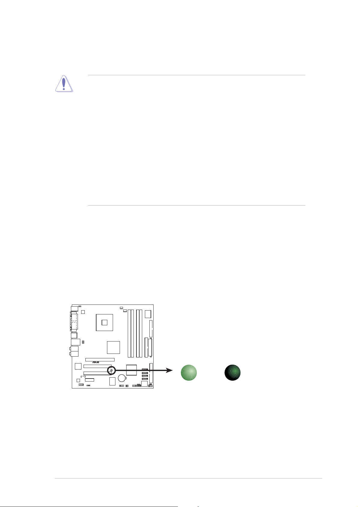
The motherboard comes with a standby power LED that lights up to
indicate that the system is ON, in sleep mode, or in soft-off mode.
This is a reminder that you should shut down the system and unplug
the power cable before removing or plugging in any motherboard
component. The illustration below shows the location of the onboard
LED.
®
P5GD1-VM
P5GD1-VM Onboard LED
ON
Standby
Power
SB_PWR1
OFF
Powered
Off
ASUS P5GD1-VMASUS P5GD1-VM
ASUS P5GD1-VM
ASUS P5GD1-VMASUS P5GD1-VM
1-51-5
1-5
1-51-5
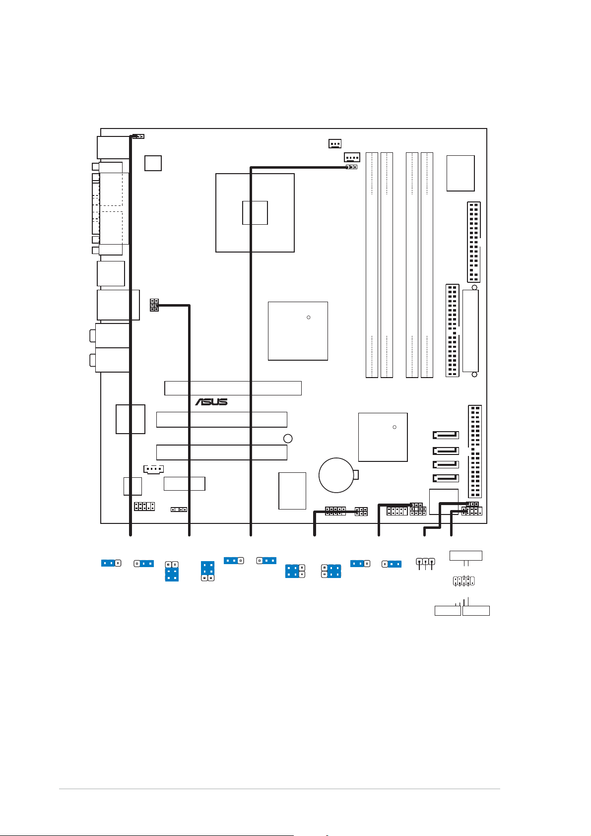
1.5 Motherboard overview
1.5.11.5.1
1.5.1
1.5.11.5.1
PS/2KBMS
T: Mouse
B: Keyboard
COM1
VGA1
F_USB12
LAN_USB34
Top:Rear Speaker Out
Center:
Side Speaker Out
Below:
Center/Subwoofer
Top:Line In
Center:Line Out
Below:Mic In
Kinnereth
82562EZ
ALC880
Motherboard layoutMotherboard layout
Motherboard layout
Motherboard layoutMotherboard layout
KBPWR1
ATX12V1
PARALLEL PORT
USBPW34
USBPW12
LGA775
PCIEX16
®
PCI1
PCI2
CD1
PCIEX1_1
AAFP1
SPDIF_OUT1
CHA_FAN1
Intel
915G
SB_PWR1
ITE
8211
CPU_FAN1
R
CMOS Power
FANPWR1
CR2032 3V
Lithium Cell
USB56
DDR DIMM_A1 (64 bit,240-pin module)
DDR DIMM_A2 (64 bit,240-pin module)
DDR DIMM_B1 (64 bit,240-pin module)
DDR DIMM_B2 (64 bit,240-pin module)
SATA 4
SATA 3
SATA 2
SATA 1
PRI_IDE1
PRI_PCIIDE1
Intel FWH
4Mb
P5GD1-VM
Intel
ICH6
USBPW56
USBPW78
R
CLRTC1
SPEAKER1
CHASSIS1USB78
I/O
Super
FLOPPY1
EATXPWR1
PLED1
F_PANEL1
1-61-6
1-6
1-61-6
KBPWR1
2312
+5V +5VSB
(Default)
USBPW12
USBPW34
2
1
+5V
(Default)
3
2
+5VSB
FANPWR1
12
(Default)
USBPW56
23
DC modePWM
USBPW78
21
+5V
(Default)
2
+5VSB
Chapter 1: Product introductionChapter 1: Product introduction
Chapter 1: Product introduction
Chapter 1: Product introductionChapter 1: Product introduction
CLRTC1
12 23
3
Normal Clear CMOS
(Default)
PLED1
1
F_PANEL1
PWRSW
NC
PLED-
PLED+
IDE_LED+
IDE LED
*
Requires an ATX power supply.
PWR
Ground
IDE_LED-
RESET
GNDReset
1.5.21.5.2
1.5.2
1.5.21.5.2
When installing the motherboard, make sure that you place it into the
chassis in the correct orientation. The edge with external ports goes to the
rear part of the chassis as indicated in the image below.
Placement directionPlacement direction
Placement direction
Placement directionPlacement direction
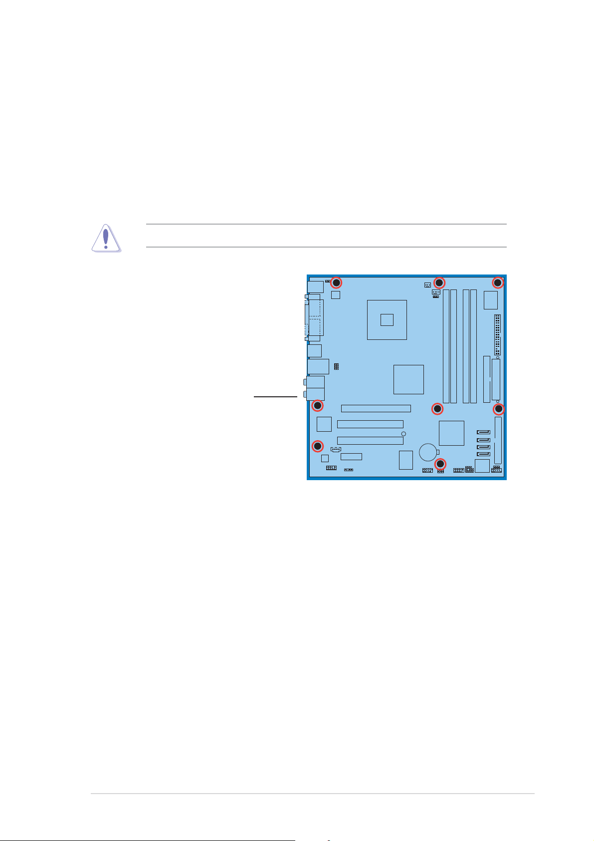
1.5.31.5.3
1.5.3
1.5.31.5.3
Screw holesScrew holes
Screw holes
Screw holesScrew holes
Place eight (8) screws into the holes indicated by circles to secure the
motherboard to the chassis.
Do not overtighten the screws! Doing so can damage the motherboard.
Place this side towardsPlace this side towards
Place this side towards
Place this side towardsPlace this side towards
the rear of the chassisthe rear of the chassis
the rear of the chassis
the rear of the chassisthe rear of the chassis
P5GD1-VM
ASUS P5GD1-VMASUS P5GD1-VM
ASUS P5GD1-VM
ASUS P5GD1-VMASUS P5GD1-VM
1-71-7
1-7
1-71-7
1.6 Central Processing Unit (CPU)
The motherboard comes with a surface mount LGA775 socket designed for
the Intel® Pentium® 4 processor in the 775-land package
•
Upon purchase of the motherboard, make sure that the LGA775
socket has its PnP cap on and the socket contacts are not bent. If
the cap is damaged or missing, or if the socket contacts are bent,
contact your retailer immediately.
•
Keep the PnP cap after installing the motherboard. ASUS will process
Return Merchandise Authorization (RMA) requests only if the
motherboard comes with the PnP cap on the LGA775 socket.
•
The warranty does not cover damage to the socket connectors
resulting from loss, misplacement, or incorrect removal of the PnP
cap.
•
Carefully inspect the motherboard
socket damage
after
purchase, you will shoulder the cost of repair.
before
buying it. If you report any
16.116.1
16.1
16.116.1
Installling the CPUInstallling the CPU
Installling the CPU
Installling the CPUInstallling the CPU
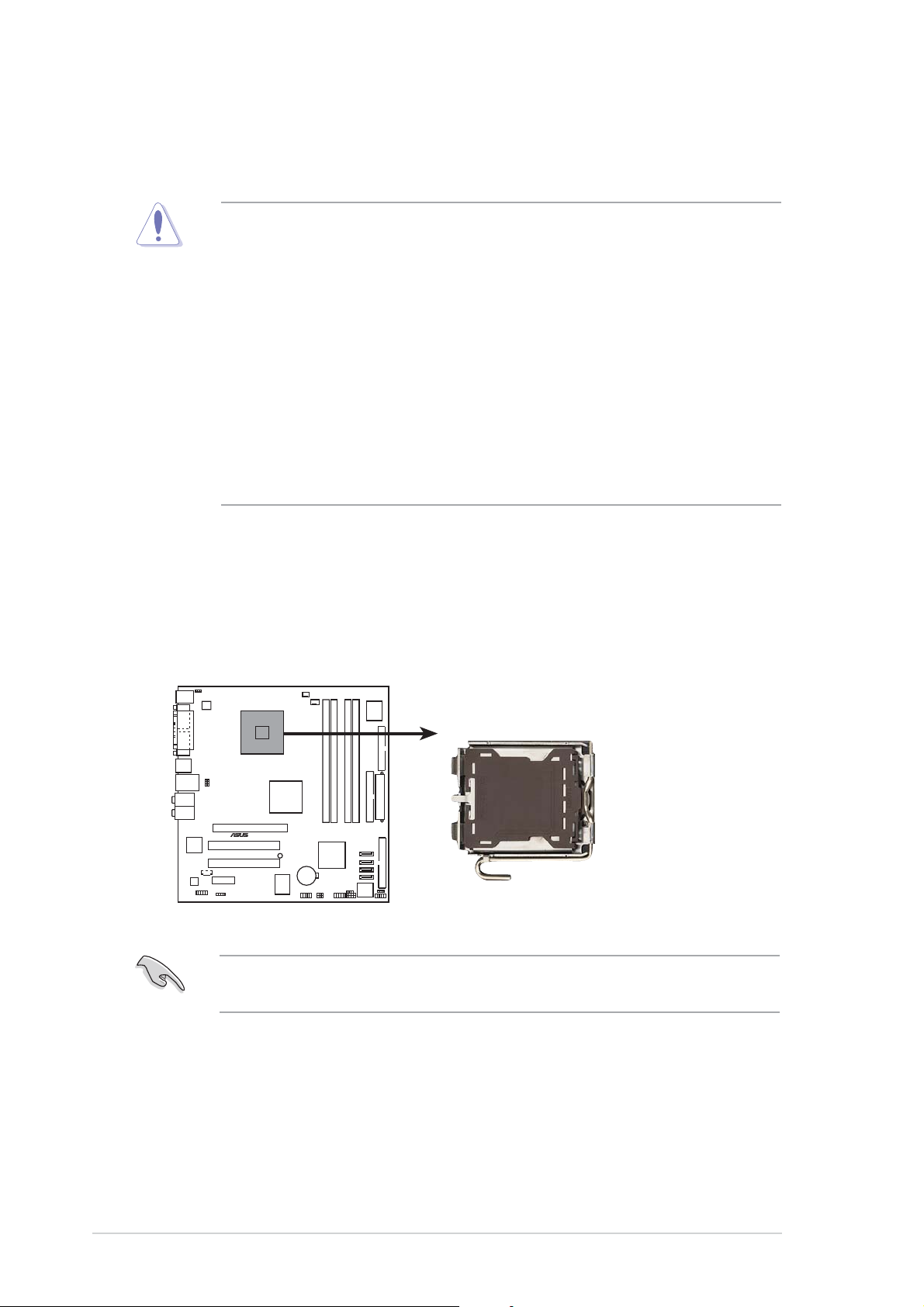
To install a CPU:
1. Locate the CPU socket on the motherboard.
®
P5GD1-VM Socket 775
Before installing the CPU, make sure that the cam box is facing towards
you and the load lever is on your left.
P5GD1-VM
1-81-8
1-8
1-81-8
Chapter 1: Product introductionChapter 1: Product introduction
Chapter 1: Product introduction
Chapter 1: Product introductionChapter 1: Product introduction
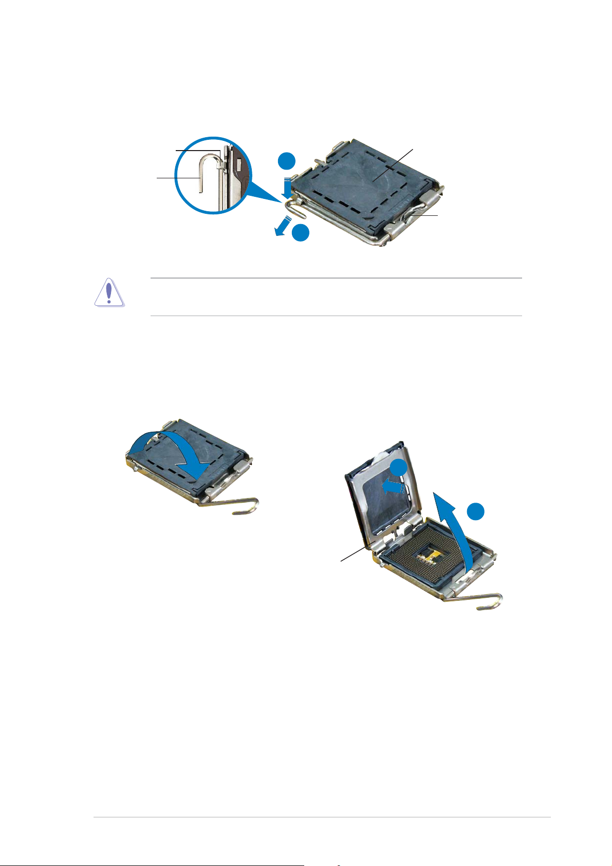
2. Press the load lever with your thumb (a), then move it to the left (b)
until it is released from the retention tab.
PnP capPnP cap
PnP cap
Retention tabRetention tab
Retention tab
Retention tabRetention tab
Load leverLoad lever
Load lever
Load leverLoad lever
To prevent damage to the socket pins, do not remove the PnP cap
unless you are installing a CPU.
A
B
PnP capPnP cap
This side ofThis side of
This side of
This side ofThis side of
the cam boxthe cam box
the cam box
the cam boxthe cam box
should faceshould face
should face
should faceshould face
you.you.
you.
you.you.
3. Lift the load lever in the
direction of the arrow to a 135º
angle.
4. Lift the load plate with your
thumb and forefinger to a
100º angle (A), then push
the PnP cap from the load
plate window to remove (B).
B
A
Load plateLoad plate
Load plate
Load plateLoad plate
ASUS P5GD1-VMASUS P5GD1-VM
ASUS P5GD1-VM
ASUS P5GD1-VMASUS P5GD1-VM
1-91-9
1-9
1-91-9
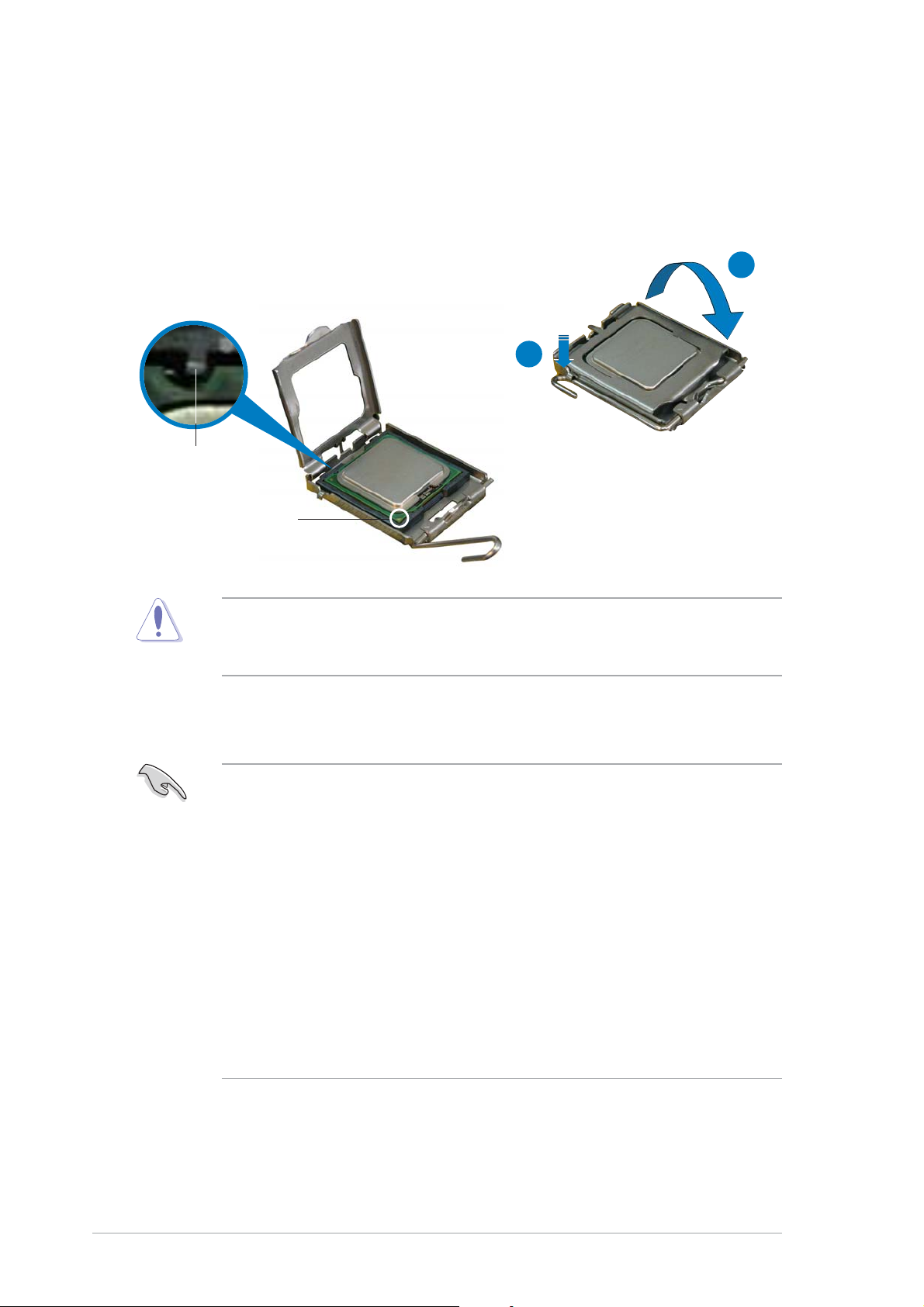
5. Position the CPU over the
socket, making sure that the
gold triangle is on the
bottom-left corner of the
socket. The socket alignment
key should fit into the CPU
notch.
Alignment keyAlignment key
Alignment key
Alignment keyAlignment key
Gold triangle markGold triangle mark
Gold triangle mark
Gold triangle markGold triangle mark
6. Close the load plate (A), then
push the load lever (B) until
it snaps into the retention
tab.
A
B
The CPU fits in only one correct orientation. DO NOT force the CPU into
the socket to prevent bending the connectors on the socket and
damaging the CPU!
Notes on IntelNotes on Intel
Notes on Intel
Notes on IntelNotes on Intel
• This motherboard supports Intel® Pentium® 4 CPUs in the 775-land
• Hyper-Threading Technology is supported under Windows
• Installing Windows
• Make sure to enable the Hyper-Threading Technology item in BIOS
• For more information on Hyper-Threading Technology, visit
®
package with Hyper-Threading Technology.
Linux 2.4.x (kernel) and later versions only. Under Linux, use the
Hyper-Threading compiler to compile the code. If you are using any
other operating systems, disable the Hyper-Threading Techonology
item in the BIOS to ensure system stability and performance.
before installing a supported operating system.
www.intel.com/info/hyperthreading.
Hyper-Threading Technology Hyper-Threading Technology
Hyper-Threading Technology
Hyper-Threading Technology Hyper-Threading Technology
®
XP Service Pack 1 is recommended.
®
XP and
1-101-10
1-10
1-101-10
Chapter 1: Product introductionChapter 1: Product introduction
Chapter 1: Product introduction
Chapter 1: Product introductionChapter 1: Product introduction

To use the Hyper-Threading Technology on this motherboard:
®
1. Install an Intel
Pentium® 4 CPU that supports Hyper-Threading
Technology.
2. Power up the system and enter the BIOS Setup (see Chapter 2). Under
the Advanced Menu, make sure that the item Hyper-Threading
Technology is set to Enabled. The item appears only if you installed a
CPU that supports Hyper-Threading Techonology.
3. Reboot the computer.
1.6.21.6.2
1.6.2
1.6.21.6.2
Installling the CPU heatsink and fanInstallling the CPU heatsink and fan
Installling the CPU heatsink and fan
Installling the CPU heatsink and fanInstallling the CPU heatsink and fan
The Intel® Pentium® 4 LGA775 processor requires a specially designed
heatsink and fan assembly to ensure optimum thermal condition and
performance.
• Install the motherboard to the chassis before you install the CPU fan
and heatsink assembly.
• When you buy a boxed Intel
includes the CPU fan and heatsink assembly. If you buy a CPU
separately, make sure that you use only Intel®-certified
multi-directional heatsink and fan.
®
• Your boxed Intel
come with installation instructions for the CPU, heatsink, and the
retention mechanism. If the instructions in this section do not match
the CPU documentation, follow the latter.
• Your Intel
a push-pin design and requires no tool to install.
®
Pentium® 4 LGA775 processor package should
Pentium® 4 LGA775 heatsink and fan assembly comes in
®
Pentium® 4 processor, the package
ASUS P5GD1-VMASUS P5GD1-VM
ASUS P5GD1-VM
ASUS P5GD1-VMASUS P5GD1-VM
1-111-11
1-11
1-111-11
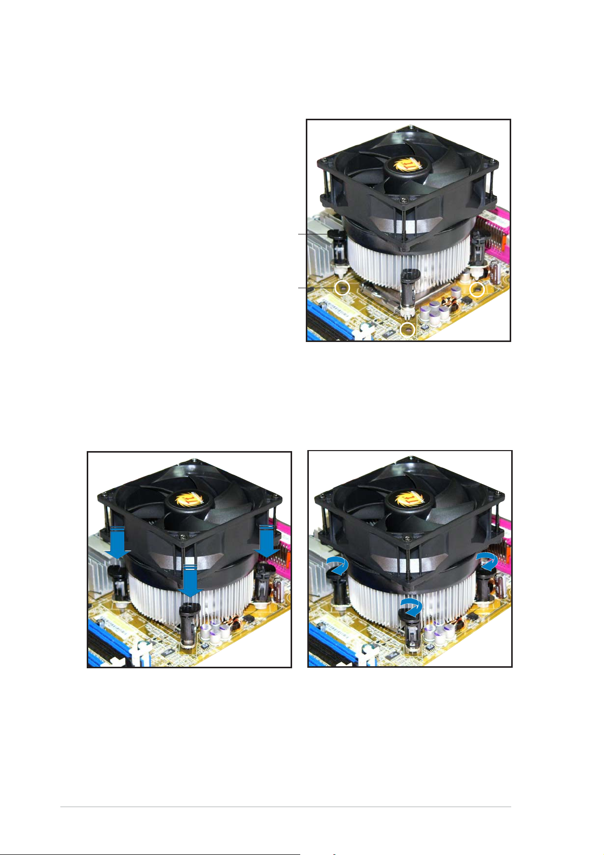
To install the CPU heatsink and fan:
1. Place the heatsink on top of the
installed CPU, making sure that
the four pins match the holes on
the motherboard.
Push pinPush pin
Push pin
Push pinPush pin
Motherboard holeMotherboard hole
Motherboard hole
Motherboard holeMotherboard hole
2. Push each of the pins
downward to secure the
heatsink and fan assembly in
place.
3. Rotate the push-pins clockwise
to lock.
1-121-12
1-12
1-121-12
Chapter 1: Product introductionChapter 1: Product introduction
Chapter 1: Product introduction
Chapter 1: Product introductionChapter 1: Product introduction
4. When the fan and heatsink assembly is in place, connect the CPU fan
cable to the connector on the motherboard labeled CPU_FAN.
CPU_FAN1
GND
CPU FAN PWR
CPU FAN IN
®
P5GD1-VM
Do not forget to connect the CPU fan connector! Hardware monitoring
errors can occur if you fail to plug this connector.
CPU FAN PWM
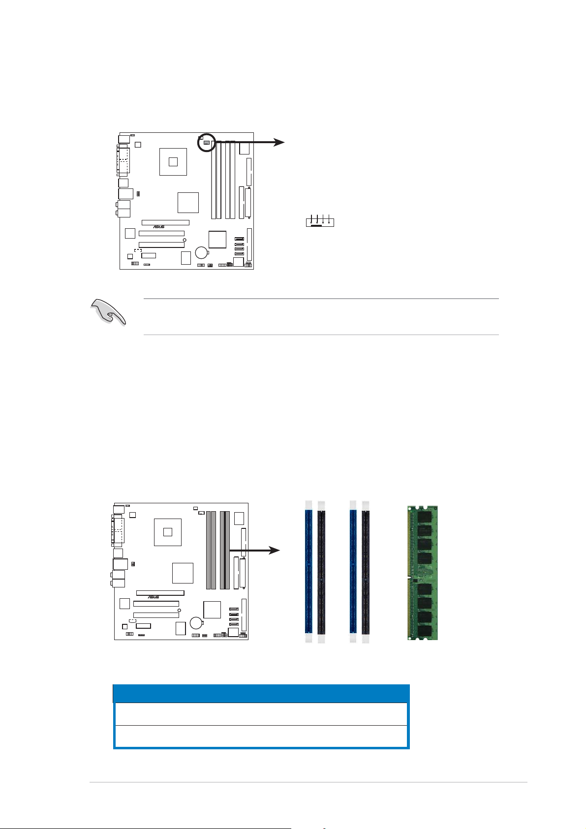
1.7 System memory
1.7.11.7.1
1.7.1
1.7.11.7.1
The motherboard comes with four 184-pin Double Data Rate (DDR) Dual
Inline Memory Modules (DIMM) sockets.
The following figure illustrates the location of the sockets:
P5GD1-VM 184-Pin DDR DIMM Sockets
DIMM sockets locationDIMM sockets location
DIMM sockets location
DIMM sockets locationDIMM sockets location
DIMM_A1
®
P5GD1-VM
DIMM_A2
DIMM_B1
DIMM_B2
ChannelChannel
Channel
ChannelChannel
Channel AChannel A
Channel A
Channel AChannel A
Channel BChannel B
Channel B
Channel BChannel B
ASUS P5GD1-VMASUS P5GD1-VM
ASUS P5GD1-VM
ASUS P5GD1-VMASUS P5GD1-VM
SocketsSockets
Sockets
SocketsSockets
DIMM_A1 and DIMM_B1DIMM_A1 and DIMM_B1
DIMM_A1 and DIMM_B1
DIMM_A1 and DIMM_B1DIMM_A1 and DIMM_B1
DIMM_A2 and DIMM_B2DIMM_A2 and DIMM_B2
DIMM_A2 and DIMM_B2
DIMM_A2 and DIMM_B2DIMM_A2 and DIMM_B2
ColorColor
Color
ColorColor
BlueBlue
Blue
BlueBlue
BlackBlack
Black
BlackBlack
1-131-13
1-13
1-131-13

1.7.21.7.2
1.7.2
1.7.21.7.2
Memory ConfigurationsMemory Configurations
Memory Configurations
Memory ConfigurationsMemory Configurations
You may install 256 MB, 512 MB and 1 GB unbuffered non-ECC DDR DIMMs
into the DIMM sockets using the memory configurations in this section.
• For dual-channel configuration, the total size of memory module(s)
installed per channel must be the same (DIMM_A1 + DIMM_B1 =
DIMM_A2 + DIMM_B2).
• Always install DIMMs with the same CAS latency. For optimum
compatibility, it is recommended that you obtain memory modules
from the same vendor. Refer to the DDR Qualified Vendors List on
the next page for details.
• Due to chipset resource allocation, the system may detect less than
4 GB system memory when you installed four 1 GB DDR memory
modules.
• This motherboard does not support memory modules made up of
128 Mb chips or double sided x16 memory modules.
1-141-14
1-14
1-141-14
Chapter 1: Product introductionChapter 1: Product introduction
Chapter 1: Product introduction
Chapter 1: Product introductionChapter 1: Product introduction
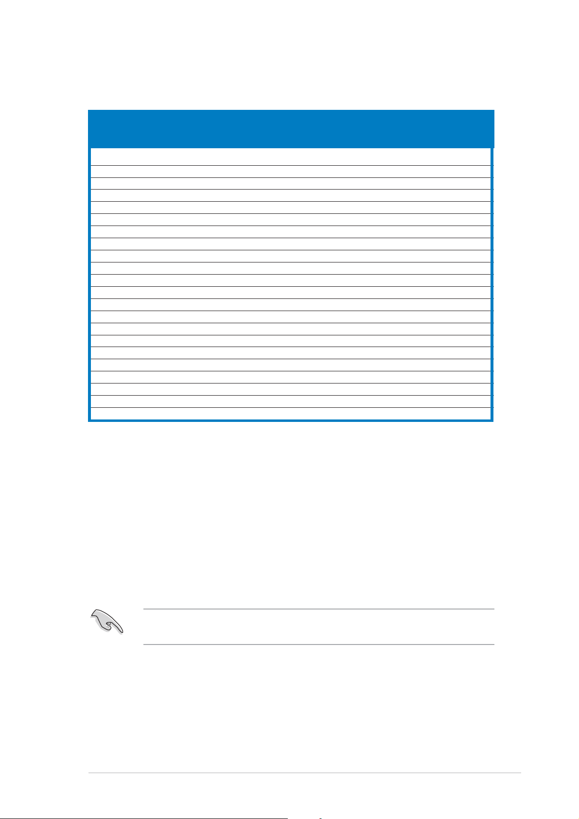
DDR (400 MHz) Qualified Vendors ListDDR (400 MHz) Qualified Vendors List
DDR (400 MHz) Qualified Vendors List
DDR (400 MHz) Qualified Vendors ListDDR (400 MHz) Qualified Vendors List
(optional) (optional)
(optional)
(optional) (optional)
SizeSize
Size
SizeSize
256 MB KINGSTON KVR400X64C3A/256 Hynix SS HY5DU56822BT-D43 — •• •
512 MB KINGSTON KVR400X64C3A/512 Hynix DS HY5DU56822BT-D43 — •• •
256 MB KINGSTON KVR400X64C3A/256 Infineon SS HYB25D256800BT-5B — •• •
512 MB KINGSTON KVR400X64C3A/512 Infineon DS HYB25D256809BT-5B — •• •
256 MB KINGSTON KVR400X64C3A/256 KINGSTON SS D3208DL2T-5 — •• •
512 MB KINGSTON KVR400X64C3A/512 KINGSTON DS D328DIB-50 — •• •
512MB KINGSTON KHX3200A/512 N/A DS Heat-Sink Package — ••
256MB SAMSUNG M368L3223ETM-CCC SAMSUNG SS K4H560838E-TCCC — •• •
512MB SAMSUNG M368L6423ETM-CCC SAMSUNG DS K4H560838E-TCCC 3 • •
256MB SAMSUNG M368L3223FTN-CCC SAMSUNG SS K4H560838F-TCCC 3 • •
512MB SAMSUNG M368L6423FTN-CCC SAMSUNG DS K4H560838F-TCCC — ••
256MB Hynix HYMD232646B8J-D43 AA Hynix SS HY5DU56822BT-D43 3 • • •
512MB Hynix HYMD264646B8J-D43 AA Hynix DS HY5DU56822BT-D43 — •• •
256MB MICRON MT8VDDT3264AG-40BCB MICRON SS MT46V32M8TG-5BC — •• •
512MB MICRON MT16VDDT6464AG-40BCB MICRON DS MT46V32M8TG-5BC — •• •
256MB Infineon HYS64D32300GU-5-B Infineon SS HYB25D256800BT-5B 3 • • •
512MB Infineon HYS64D64320GU-5-B Infineon DS HYB25D256800BT-5B 3 • •
256MB Infineon HYS64D32300HU-5-C Infineon SS HYB25D256800CE-5C 3 • • •
512MB Infineon HYS64D64320HU-5-C Infineon DS HYB25D256800CE-5C — •• •
256MB CORSAIR CMX256A-3200C2PT Winbond SS W942508BH-5 2 • • •
512MB CORSAIR CMX512-3200C2 Winbond DS Heat-Sink Package 2 • • •
512MB CORSAIR VS512MB400
VendorVendor
Vendor
VendorVendor
ModelModel
Model
ModelModel
BrandBrand
Brand
BrandBrand
VALUE seLecT DS VS32M8-5 2.5 • • •
Side(s)Side(s)
Side(s)
Side(s)Side(s)
ComponentComponent
Component
ComponentComponent
DIMM support DIMM support
DIMM support
DIMM support DIMM support
CLCL
AA
BB
CL
CLCL
A
AA
CC
B
C
BB
CC
SSSS
S S - Single-sided
SSSS
DSDS
D S - Double-sided
DSDS
CLCL
C L- CAS Latency
CLCL
DIMM support:DIMM support:
DIMM support:
DIMM support:DIMM support:
A A
A - supports one module inserted into either slot, in a Single-channel memory
A A
configuration.
BB
B - supports one pair of modules inserted into either the blue slots or the black
BB
slots as one pair of Dual-channel memory configuration.
C C
C - supports four modules inserted into the blue and black slots as two pairs of
C C
Dual-channel memory configuration.
Visit the ASUS website (www.asus.com) for the latest DDR Qualified
Vendors List.
ASUS P5GD1-VMASUS P5GD1-VM
ASUS P5GD1-VM
ASUS P5GD1-VMASUS P5GD1-VM
1-151-15
1-15
1-151-15
1.7.31.7.3
1.7.3
1.7.31.7.3
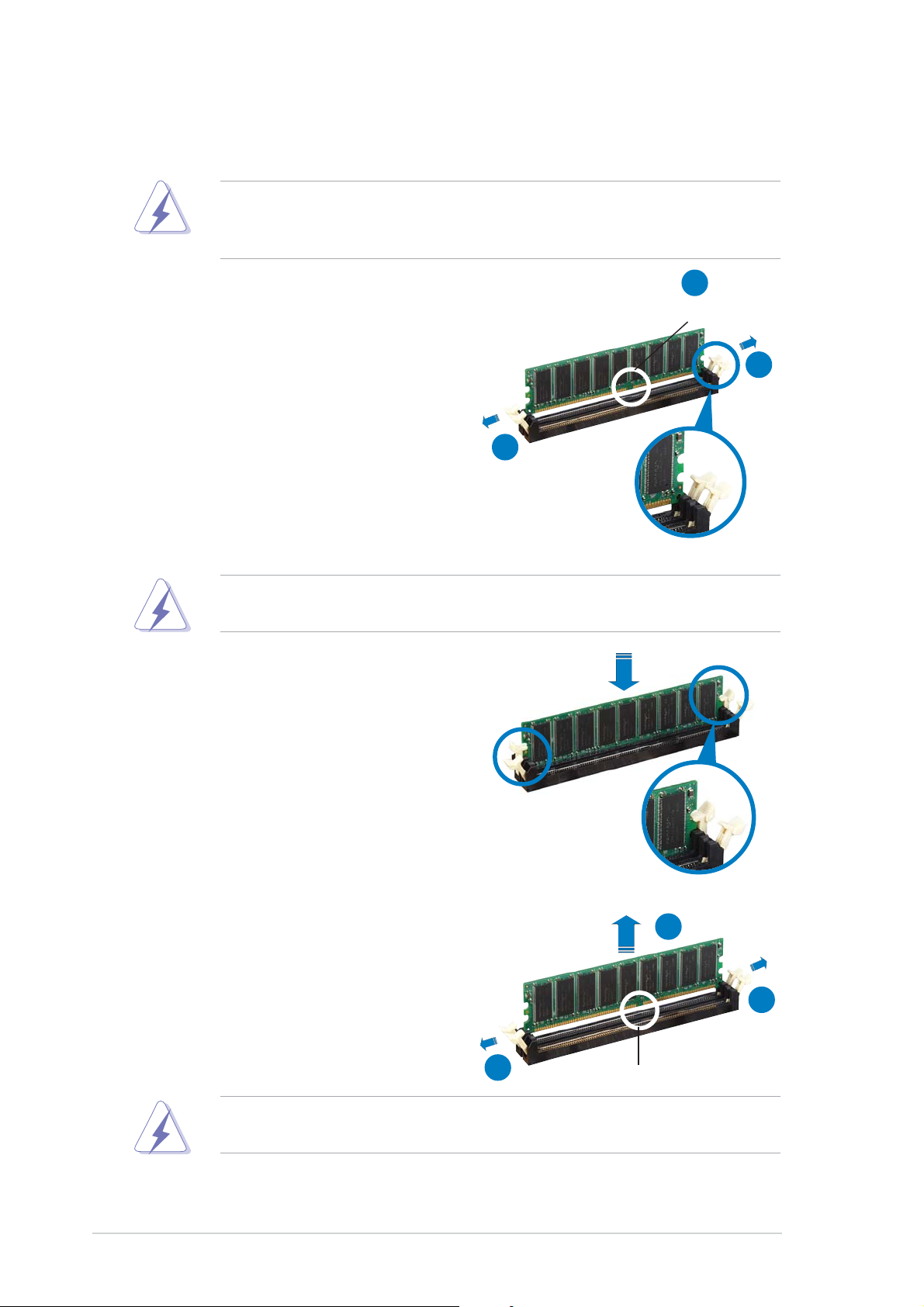
Installing a DIMMInstalling a DIMM
Installing a DIMM
Installing a DIMMInstalling a DIMM
Make sure to unplug the power supply before adding or removing DIMMs
or other system components. Failure to do so may cause severe damage
to both the motherboard and the components.
1. Unlock a DIMM socket by
pressing the retaining clips
outward.
2. Align a DIMM on the socket such
that the notch on the DIMM
matches the break on the
socket.
A DDR DIMM is keyed with a notch so that it fits in only one direction.
DO NOT force a DIMM into a socket to avoid damaging the DIMM.
2
DDR DIMM notchDDR DIMM notch
DDR DIMM notch
DDR DIMM notchDDR DIMM notch
1
1
Unlocked retaining clipUnlocked retaining clip
Unlocked retaining clip
Unlocked retaining clipUnlocked retaining clip
3. Firmly insert the DIMM into the
socket until the retaining clips
snap back in place and the DIMM
is properly seated.
Locked Retaining ClipLocked Retaining Clip
Locked Retaining Clip
Locked Retaining ClipLocked Retaining Clip
1.7.41.7.4
1.7.4
1.7.41.7.4
Removing a DIMMRemoving a DIMM
Removing a DIMM
Removing a DIMMRemoving a DIMM
Follow these steps to remove a DIMM.
1. Simultaneously press the
retaining clips outward to unlock
the DIMM.
Support the DIMM lightly with your fingers when pressing the retaining
clips. The DIMM might get damaged when it flips out with extra force.
2
1
1
DDR DIMM notchDDR DIMM notch
DDR DIMM notch
DDR DIMM notchDDR DIMM notch
2. Remove the DIMM from the socket.
1-161-16
1-16
1-161-16
Chapter 1: Product introductionChapter 1: Product introduction
Chapter 1: Product introduction
Chapter 1: Product introductionChapter 1: Product introduction

1.8 Expansion slots
In the future, you may need to install expansion cards. The following
sub-sections describe the slots and the expansion cards that they support.
Make sure to unplug the power cord before adding or removing
expansion cards. Failure to do so may cause you physical injury and
damage motherboard components.
1.8.11.8.1
1.8.1
1.8.11.8.1
To install an expansion card:
1. Before installing the expansion card, read the documentation that
came with it and make the necessary hardware settings for the card.
2. Remove the system unit cover (if your motherboard is already
installed in a chassis).
3. Remove the bracket opposite the slot that you intend to use. Keep
the screw for later use.
4. Align the card connector with the slot and press firmly until the card is
completely seated on the slot.
5. Secure the card to the chassis with the screw you removed earlier.
6. Replace the system cover.
1.8.21.8.2
1.8.2
1.8.21.8.2
After installing the expansion card, configure the it by adjusting the
software settings.
Installing an expansion cardInstalling an expansion card
Installing an expansion card
Installing an expansion cardInstalling an expansion card
Configuring an expansion cardConfiguring an expansion card
Configuring an expansion card
Configuring an expansion cardConfiguring an expansion card
1. Turn on the system and change the necessary BIOS settings, if any.
See Chapter 2 for information on BIOS setup.
2. Assign an IRQ to the card. Refer to the tables on the next page.
3. Install the software drivers for the expansion card.
ASUS P5GD1-VMASUS P5GD1-VM
ASUS P5GD1-VM
ASUS P5GD1-VMASUS P5GD1-VM
1-171-17
1-17
1-171-17
 Loading...