


Service Source
PowerBook G4 (15-inch Double-Layer SD)
19 October 2005
© 2005 Apple Computer, Inc. All rights reserved.

Service Source
Basics
PowerBook G4 (15-inch Double-Layer SD)
© 2005 Apple Computer, Inc. All rights reserved.
General Information
Overview
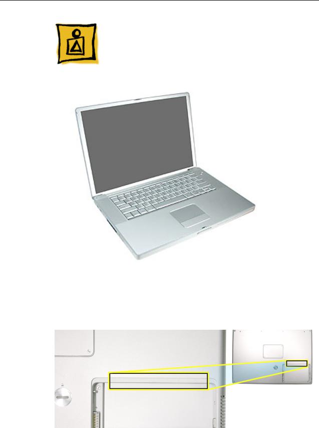
From the exterior, the PowerBook G4 (15-inch Double-Layer SD) physically is identical to its predecessor, the PowerBook G4 (15-inch 1.67/1.5GHz). Both lack the customer accessible AirPort door in the battery bay.
General Information |
PowerBook G4 (15-inch Double-Layer SD) Basics - 1 |
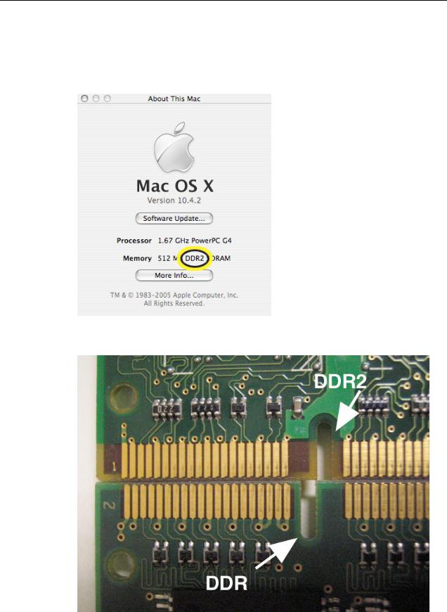
The quickest ways to identify the PowerBook G4 (15-inch Double-Layer SD) computer:
•If the system is bootable, power it on. After pressing the power button the sleep LED light comes on solid and stays on until video appears onscreen.
•Also the "About this Mac." Under Memory, shows DDR2 memory.
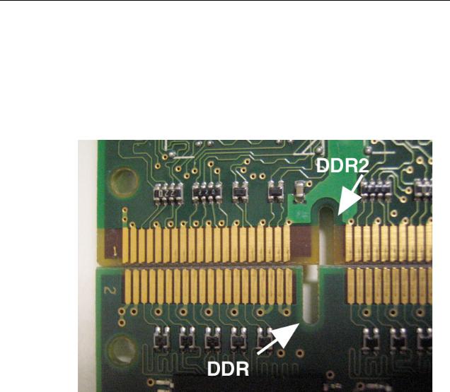
• Check a memory card to see if it is DDR2 (keyed differently than DDR)
2 - PowerBook G4 (15-inch Double-Layer SD) Basics |
General Information |
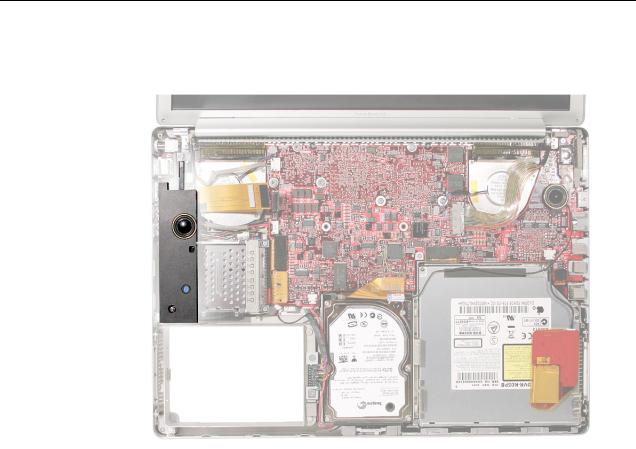
•With the top case removed, there is no mid-range speaker module (which has been above the hard drive on all previous aluminum PowerBook G4 15-inch models).
Main feature differences from the previous models:
•Higher resolution 15.2-inch display, 1440 x 960, 114 dpi (previously 1280 x 854, 101 dpi)
•Supports DDR2 memory up to 2GB
•128MB VRAM with dual link DVI option is now standard
•Double-Layer SuperDrive allows users to burn two layers through a single side of a double-layer burnable disc.
•80GB 5400 RPM hard drive standard
•100GB/120GB 5400 RPM, 100GB 7200 RPM hard drive option
Some key features common to the two previous models that distinguish these computers from earlier PowerBook models, include:
•Aluminum alloy enclosure
•Built-in FireWire 800 port
•Supports USB 2.0
General Information |
PowerBook G4 (15-inch Double-Layer SD) Basics - 3 |

New Parts and Procedures
•Main Battery
–The main battery has a new capacity sensing circuit design. It looks the same as previous batteries and is interchangeable. However, it has a different battery calibration procedure. A new calibration procedure has been developed which works on both batteries. Look in the Troubleshooting section, Battery Short Life for details. This change does not apply to the PowerBook G4 17-inch.
•Top Case
–As the sleep magnet has been relocated to the display bezel, the sleep sensor has moved from the trackpad flex to the edge of the top case. Previous top cases will not work with this system.
•Keyboard
–The keyboard has a narrower flex than the previous integrated backlight keyboard used in the PowerBook G4 (15-inch 1.67/1.5GHz). These two keyboards are not interchangeable. This keyboard is the same as on the PowerBook G4 (17-inch Double-Layer SD).
•Mass Storage (Hard drive and optical drive)
–Both devices share a single ATA bus using a cable select addressing scheme. Previously each drive was a master device on separate ATA busses. Although, an older hard drive may work in this system, the optical drive will either not show up as a device or cause the system to not boot-up properly.
•AirPort Extreme and Bluetooth 2.0
–These two functions have been combined on a single card.
–The card has the antenna diversity function built-in, eliminating that card in the clutch cover.
•Main Logic Board
–A new thermal grease is used. It has a greyish color.
Other minor differences include cable shapes, routing, connector types, locations, screws, brackets, and part designs.
4 - PowerBook G4 (15-inch Double-Layer SD) Basics |
General Information |
Important Memory Note
Memory from previous 15-inch (Titanium-series) PowerBooks is not compatible with this computer.
Memory from previous PowerBook G4 (15-inch FW800), PowerBook G4 (15-inch 1.5/ 1.33GHz), and PowerBook G4 (15-inch 1.67/1.5GHz) is physically not compatible. DDR2 is keyed differently than DDR memory.
Service Manual Note
In this manual, graphics or photos are intended to help illustrate procedures or information, only, and may show a different level of disassembly, or show a different configuration or computer model, than your computer.
Kapton® Tape Note
See Kapton Tape topic below.
Cable Routing Note
During disassembly, note cable routing. Reassemble in the same manner. Verify that cables do not route over components when they should route into lower positions or channels. Verify that the cables are not strained or applying pressure onto other components.
General Information |
PowerBook G4 (15-inch Double-Layer SD) Basics - 5 |

Tools
The following tools are recommended for the take apart procedures.
•ESD wrist strap and mat
•Soft cloth
•#0 Phillips screwdriver (magnetized)
•#1 Phillips screwdriver (magnetized)
•5 mm socket wrench
•1.5 mm Hex key (or Torx T6)
•Needlenose pliers
•Torx T8 screwdriver
•Torx T6 screwdriver
•Thermal grease (922-7144)
•Gasket kit (076-1201)
•Alcohol pads
•Black stick (nylon probe tool 922-5065) (or other nonconductive nylon or plastic flatblade tool)
•Multi-compartment screw tray (such as a plastic ice cube tray)
•Kapton tape (922-1731 (0.5-inch x 12-yard roll))
•Apple Pro keyboard and mouse (for troubleshooting)
Serial Number Location
The serial number is located in the battery bay.
6 - PowerBook G4 (15-inch Double-Layer SD) Basics |
General Information |

Kapton Tape
Tools
This procedure requires the following tools:
•Kapton tape (922-1731 (0.5-inch x 12-yard roll))
•Scissors or tape dispenser
Procedure
Kapton tape is used to secure cables and connectors where necessary.
During disassembly, note any Kapton tape use and locations—reapply in the same manner. Do not over apply or build up tape on top of old tape; space tolerances are tight and build up or extraneous use of tape may cause pressure on other components.
Refer to the picture below throughout this manual as a guide to replacing Kapton tape.
Kapton Tape |
PowerBook G4 (15-inch Double-Layer SD) Basics - 7 |

Service Source
Take Apart
PowerBook G4 (15-inch Double-Layer SD)
© 2005 Apple Computer, Inc. All rights reserved.
Foot
Tools
This procedure requires the following tools:
•Foot kit
•Tweezers or needlenose pliers
•Soft cloth
Preliminary Step
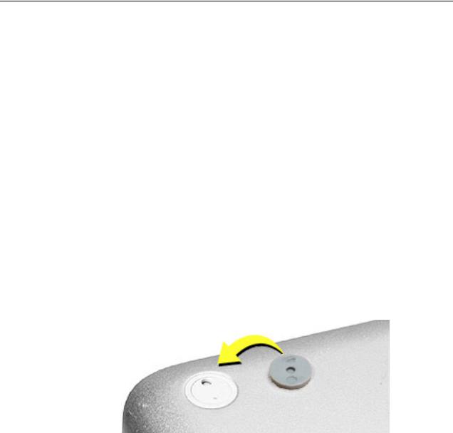
Before you begin, check the foot location that needs replacement and verify that the case plug is attached. Also verify that the case plug, and the case foot in the kit, match the pictures below.
Plug Area on Bottom Case |
Matching Foot |
Action |
|||||
|
|
|
|
|
|
|
|
Missing case plug |
Not available for |
Replace the bottom |
|||||
|
|
|
|
replacement |
case, or send to Apple |
||
|
|
|
|
|
|
|
Repair Center. |
|
|
|
|
|
|
|
|
|
|
|
|
|
|
|
|
Case plug |
Case foot |
Continue with the |
|||||
|
|
|
|
|
|
|
procedure, matching |
|
|
|
|
|
|
|
|
|
|
|
|
|
|
|
the foot to the plug on |
|
|
|
|
|
|
|
the bottom case. |
|
|
|
|
|
|
|
|
|
|
|
|
|
|
|
|
Foot |
PowerBook G4 (15-inch Double-Layer SD) Take Apart - 1 |
Procedure
Warning: The glue used in this procedure can bond instantly to skin. Do not touch the glue. In the event of contact, review the safety instructions at the end of this document. For additional information, refer to the glue manufacturer:
Elmer's Products, Inc.
Columbus, OH. 43215-3799
www.krazyglue.com
1.Place the computer upside down on a clean, lint-free cloth or other nonabrasive surface.
2.Select a foot from the kit. Verify that the case plug and case foot match (refer to the images shown in the table). Do not use a foot that does not match.
3.Make sure the plug area on the bottom case is clean. If any portion of the soft rubber foot remains, remove it so that only the hard plastic plug is visible.
Important: When positioning the foot, make sure the indents and bumps of the rubber foot match up and fit into the corresponding indents and bumps in the plug. This ensures a balanced and level fitting. (Note: The picture below is of a different foot than on the computer, and is for illustration only.)
2 - PowerBook G4 (15-inch Double-Layer SD) Take Apart |
Foot |

4.Warning: GLUE IS AN EYE AND SKIN IRRITANT. BONDS SKIN INSTANTLY. Do not touch the glue at any time. Before opening the glue, review the safety instructions at the end of this document.
Important: The glue tube included in the kit is sealed until first use. Do not break the seal until you are ready to use the glue. To break the seal, hold the tube upright and away from you. Place the hollow nozzle cap on the tube and tighten it all the way down. The tube is then ready to dispense the glue through the nozzle cap.
5.Apply one drop of glue to the plug on the bottom case. Do not spread the glue.
6.Using tweezers or needlenose pliers, carefully position the new foot so its textured surface fits into the inner ring of the plug.
7.Using the end of the tweezers or pliers—not your finger—lightly press and hold the foot in place for 30 seconds.
8.Before turning over the computer, allow the glue to set for at least 15 minutes.
9.Discard the tube of glue.
SAFETY INSTRUCTIONS: GLUE IS AN EYE AND SKIN IRRITANT. BONDS SKIN INSTANTLY. Contains ethyl cyanoacrylate. Avoid contact with skin and eyes. If eye or mouth contact occurs, hold eyelid or mouth open and rinse thoroughly but gently with water only for 15 minutes and GET MEDICAL ATTENTION. Liquid glue will sting eye temporarily. Solidified glue may irritate eye like a grain of sand and should be treated by an eye doctor. If skin bonding occurs, soak in acetone-based nail polish remover or warm soapy water and carefully peel or roll skin apart (do not pull). Contact through clothing may cause skin burn. If spilled on clothing, flush with cold water. Avoid prolonged breathing of vapors. Use with adequate ventilation. KEEP OUT OF REACH OF CHILDREN.
Foot |
PowerBook G4 (15-inch Double-Layer SD) Take Apart - 3 |
Battery
Tools
This procedure requires the following tools:
•Soft cloth
•Coin
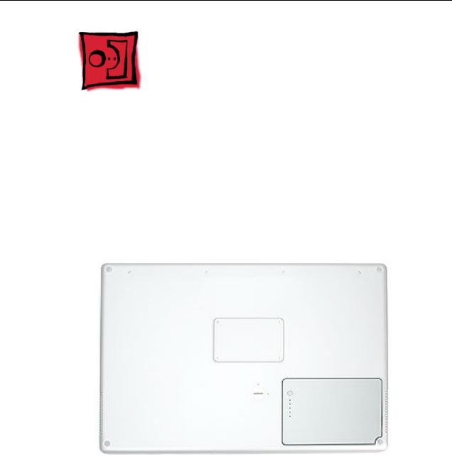
Part Location
Preliminary Steps
Warning: Always shut down the computer before opening it to avoid damaging its internal components or causing injury. After you shut down the computer, the internal components can be very hot. Let the computer cool down before continuing.
4 - PowerBook G4 (15-inch Double-Layer SD) Take Apart |
Battery |
Procedure
Warning: If the computer has been recently operating, allow it to cool down before performing this procedure.
1.Shut down the computer.
2.Disconnect the power cord and any other cables connected to the computer.
3.Place the computer face down on a soft cloth.
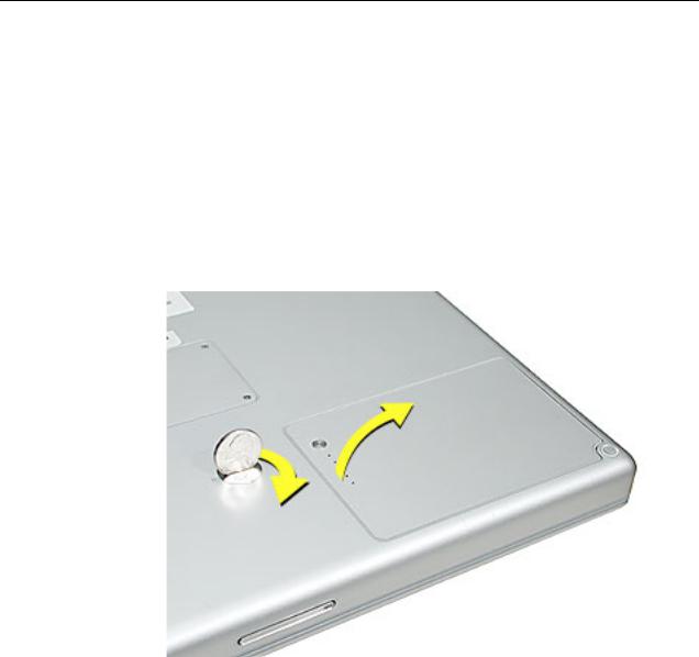
4.Insert a coin in the battery lock slot and turn it one quarter turn clockwise. The battery should raise up slightly. Lift the battery out of the battery bay.
Battery |
PowerBook G4 (15-inch Double-Layer SD) Take Apart - 5 |
Memory Door and
Memory Cards
Tools
This procedure requires the following tools:
•Soft cloth
•#0 Phillips screwdriver
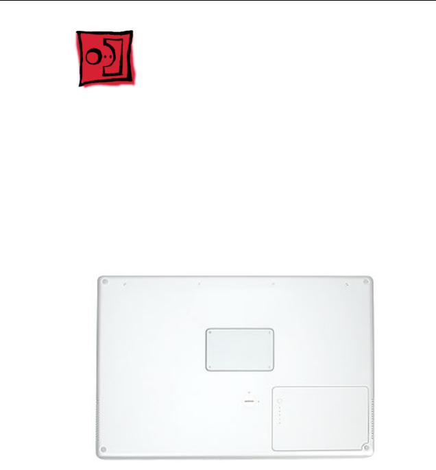
Part Location
Preliminary Steps
Before you begin, remove the battery.
6 - PowerBook G4 (15-inch Double-Layer SD) Take Apart |
Memory Door and Memory Cards |
Procedure
Warning: If the computer has been recently operating, allow it to cool down before performing this procedure.
1.Place the computer face down on a soft cloth.
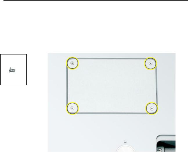
2.Remove the four screws from the memory door then remove the door.
922-6091
3.4 mm
Note: If only one memory card is installed, the factory installs it in the bottom memory slot.
Note: Memory must be removed from the top slot before removing from the bottom slot.
Memory Door and Memory Cards |
PowerBook G4 (15-inch Double-Layer SD) Take Apart - 7 |
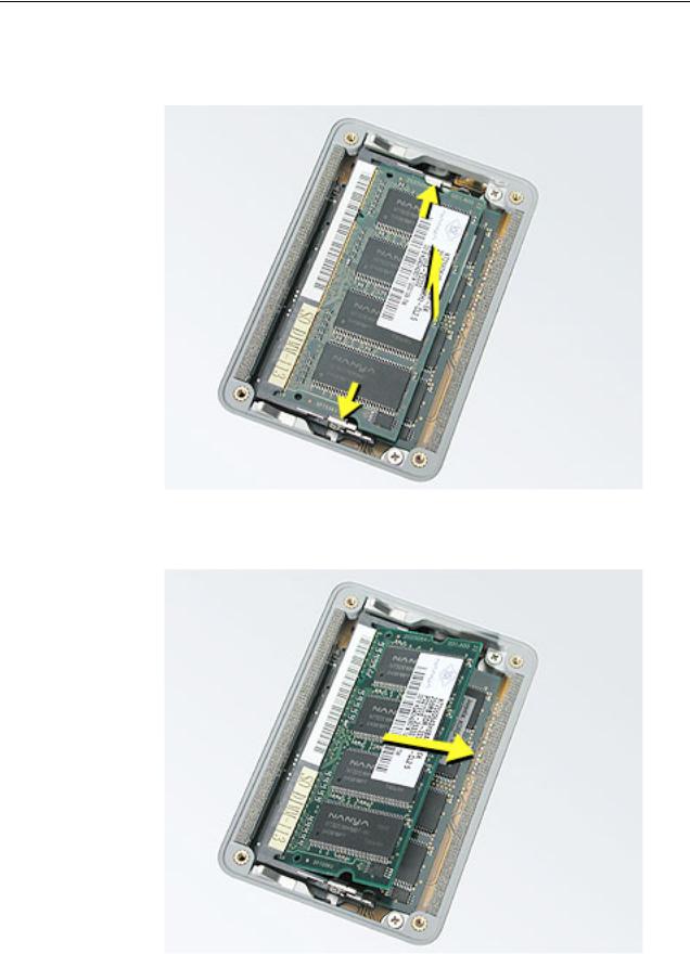
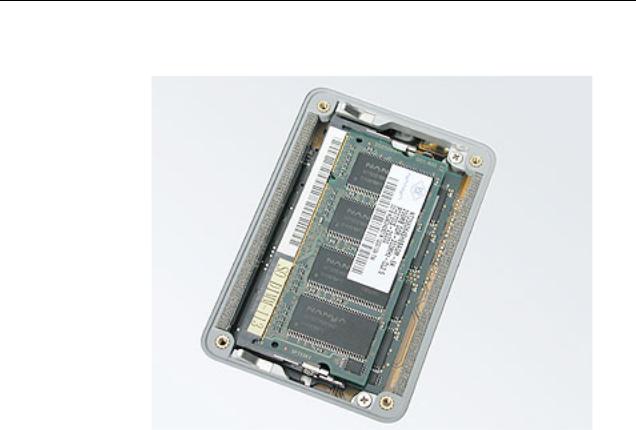
3.To remove memory cards, carefully spread the two locking tabs for the slot (top or bottom) away from the card on both sides and allow the card to pop up slightly.
4. Pull the card straight back and out of the memory slot.
8 - PowerBook G4 (15-inch Double-Layer SD) Take Apart |
Memory Door and Memory Cards |
Replacement Procedure
Notes:
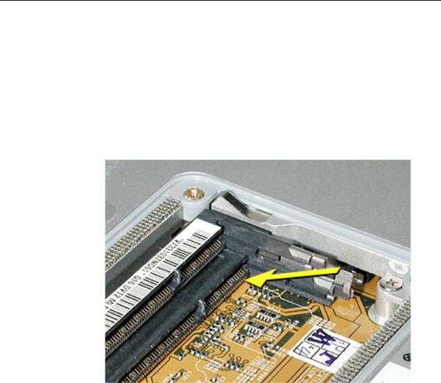
•DDR memory cards do not fit in this slot (different notch location).
•The top and bottom memory cards are inserted at different angles.
•If installing two cards, install into the bottom slot first.
•Align the notch in the memory card with the tooth in the slot before inserting.
1.To install a memory card into the bottom slot, insert the card at a low angle behind the locking tabs of the top slot.
Memory Door and Memory Cards |
PowerBook G4 (15-inch Double-Layer SD) Take Apart - 9 |
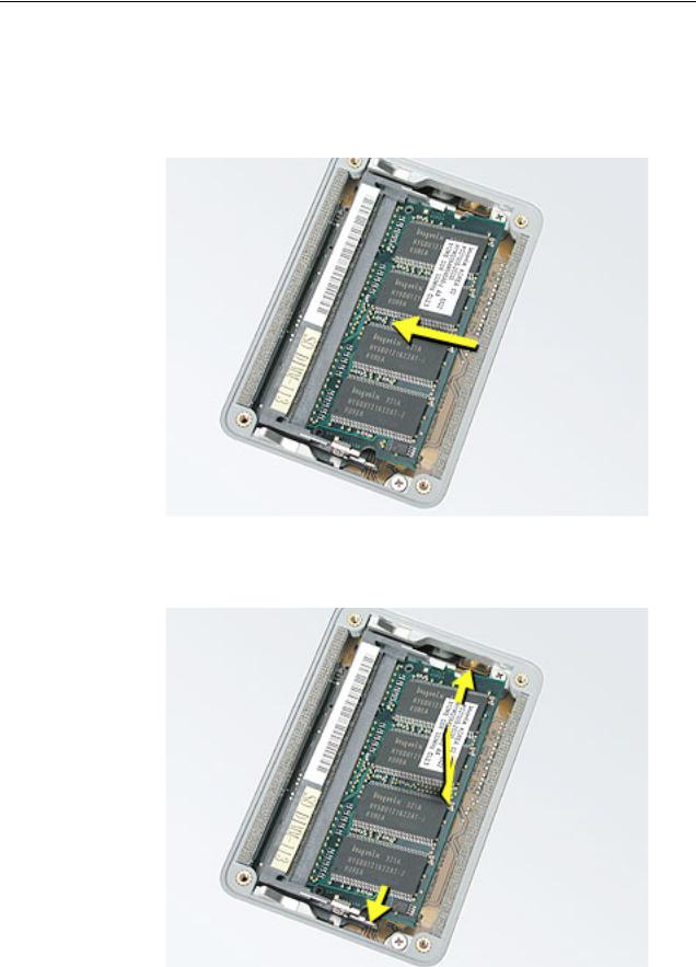
2.Slide the card forward to the lower slot. Firmly push the card straight into the slot until it is fully and securely seated along its length.
Note: If the back of the card drops down before it is fully seated, raise it up enough to push it fully into the slot.
3.Carefully spread the two locking tabs for the bottom slot away from the card on both sides while pushing the card straight down until the tabs click onto both sides of the card, locking it into place.
10 - PowerBook G4 (15-inch Double-Layer SD) Take Apart |
Memory Door and Memory Cards |
4.If installing a memory card in the top slot, follow the same procedures as the bottom slot except insert the card at a 30-degree angle, above the locking tabs.
5.Push the card in until it is firmly seated.
6.As with the bottom slot, spread the locking tabs for the top slot while pushing the card straight down until it locks into place.
Memory Door and Memory Cards |
PowerBook G4 (15-inch Double-Layer SD) Take Apart - 11 |
7. Cards should be flat and secure on both sides.
8.Install the memory door.
9.Replace the battery.
10.Use Apple System Profiler to verify that the memory is recognized. (Choose the menu bar Apple logo ( ) > About This Mac, click More Info..., select the System Profile tab, open the Memory Overview.)
12 - PowerBook G4 (15-inch Double-Layer SD) Take Apart |
Memory Door and Memory Cards |
Top Case
Tools
This procedure requires the following tools:
•#0 Phillips screwdriver (magnetized)
•1.5 mm Hex key (or Torx T6)
•Black stick (or other nonconductive nylon or plastic flat-blade tool)
•Soft cloth
•Multi-compartment screw tray
Part Location
Top Case |
PowerBook G4 (15-inch Double-Layer SD) Take Apart - 13 |
922-6095
16
922-6719
12.6 mm
922-6091
3.4 mm
Preliminary Steps
Before you begin, remove the following:
•Battery
•Memory door
Procedure
Note: This procedure removes the top case and keyboard assembly. The keyboard is removable only after removing the top case.
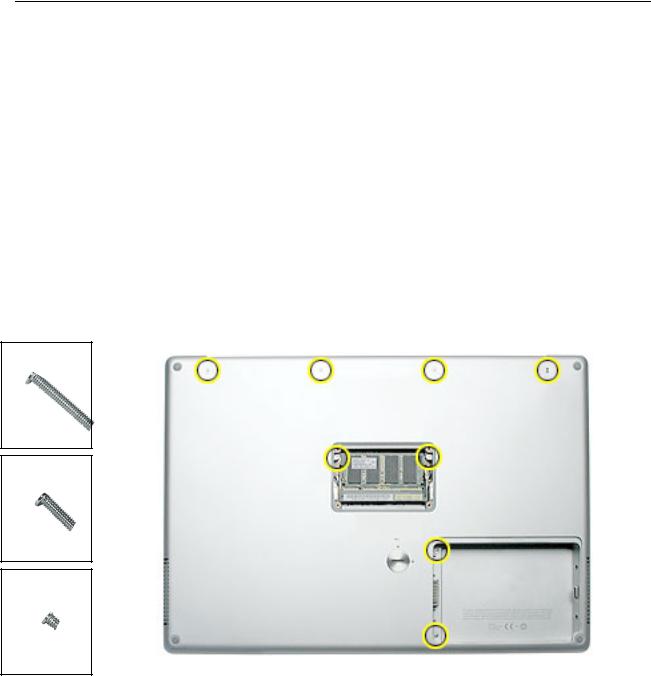
1.Place the computer face down on a soft cloth.
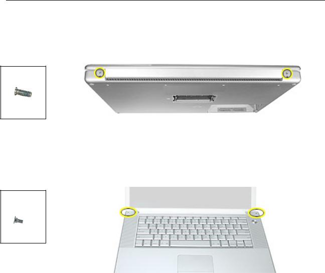
2.Remove the two screws inside the battery bay.
3.Remove the two screws from the memory bay.
4.Remove the four screws along the back edge.
14 - PowerBook G4 (15-inch Double-Layer SD) Take Apart |
Top Case |
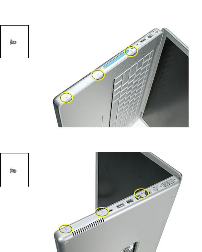
5. With the display open, rest the computer on one side. Remove the three screws.
922-6091
3.4 mm
6. Turn over the computer and remove the three screws on the other side.
922-6091
3.4 mm
Top Case |
PowerBook G4 (15-inch Double-Layer SD) Take Apart - 15 |
7.Open the computer slightly and rest it with the back facing up. Remove the two top screws along the back.
Note: Do not remove the bottom screws.
922-6100
5.3 mm
8.Lay the computer right side up and open the display slightly past 90-degrees.
9.Remove the two hex screws at the back corners of the top case (a Torx T6 can also be used).
922-6096
1.5mm Hex
4.4mm
16 - PowerBook G4 (15-inch Double-Layer SD) Take Apart |
Top Case |
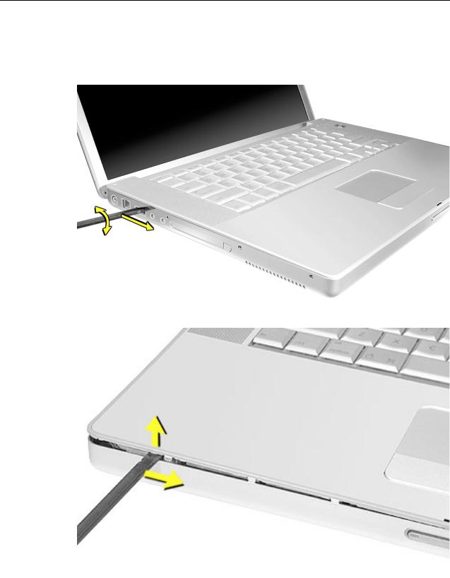
10.Along the left side, near the back, insert a black stick into the space between the top and bottom case. Work the black stick forward with a twisting motion until the black stick can be inserted on the left side of the front.
Top Case |
PowerBook G4 (15-inch Double-Layer SD) Take Apart - 17 |

11. Loosen the back right side, if needed.
12.Work the left side up until the four catches over the optical drive slot release along the right side, then lift the top case straight up, slightly, to release it completely, but do not remove.
18 - PowerBook G4 (15-inch Double-Layer SD) Take Apart |
Top Case |

13.Lift the front of the top case and pivot along the back edge to about 45-degrees, to expose the keyboard flex cable connected to the logic board.
Important: Do not lift off the top case or strain the keyboard flex cable.
14.Remove any Kapton tape from the keyboard connector on the logic board, then use a black stick to disconnect the flex cable. Lift off the top case.
Replacement Note: When reinstalling, reapply Kapton tape where it was removed.
Top Case |
PowerBook G4 (15-inch Double-Layer SD) Take Apart - 19 |

Replacement Procedure
Note: If replacing the top case, remove the keyboard and transfer to the replacement top case.
1.Visually check to verify that all cables are connected and routed correctly with nothing raised up or incorrectly over a component.
2.Check perimeter wiring and cables around clutches to verify that they will not be caught or pinched by the top case during replacement.
3.Verify that the LVDS cable is secure and lays flat.
4. On the top case, check cable connections and routing.
20 - PowerBook G4 (15-inch Double-Layer SD) Take Apart |
Top Case |
 Loading...