


Service Source
PowerBook G4 (17-inch
Double-Layer SD)
PowerBook G4 (17-inch 1.67GHz)
PowerBook G4 (17-inch 1.5GHz)
PowerBook G4 (17-inch 1.33GHz)
19 October 2005
© 2005 Apple Computer, Inc. All rights reserved.
Service Source
Basics
PowerBook G4 (17-inch Double-Layer SD)
PowerBook G4 (17-inch 1.67GHz)
PowerBook G4 (17-inch 1.5GHz)
PowerBook G4 (17-inch 1.33GHz)
© 2005 Apple Computer, Inc. All rights reserved.
General Information
Overview
Some key features that distinguish these computers from the previous 17-inch PowerBook:
|
PowerBook G4 |
|
|
|
|
(17-inch |
PowerBook G4 |
PowerBook G4 |
PowerBook G4 |
|
Double-Layer |
(17-inch |
(17-inch |
(17-inch |
|
SD) |
1.67GHz) |
1.5GHz) |
1.33GHz) |
|
|
|
|
|
Microprocessor |
1.67 GHz |
1.67 GHz |
1.5GHz |
1.33GHz |
|
|
|
|
|
L2 Cache (on-chip) |
512K |
512K |
512K |
512K |
|
|
|
|
|
Graphics Chip |
ATI Mobility |
ATI Mobility |
ATI Mobility |
ATI Mobility |
|
Radeon 9700 |
Radeon 9700 |
Radeon 9700 |
Radeon 9600 |
|
128MB VRAM |
128MB VRAM |
64MB VRAM |
|
|
w/ dual link DVI |
w/ dual link DVI |
(optional 128MB) |
|
|
|
|
|
|
USB |
2.0 |
2.0 |
2.0 |
2.0 |
|
|
|
|
|
SuperDrive |
Double-Layer |
8x DVD |
4x DVD |
2x DVD |
|
8x DVD |
|
|
|
|
|
|
|
|
General Information |
PowerBook G4 (17-inch DLSD/1.67/1.5/1.33GHz) Basics - 1 |
From the exterior, the PowerBook G4 (17-inch Double-Layer SD) physically is identical to its predecessor, the PowerBook G4 (17-inch 1.67GHz).
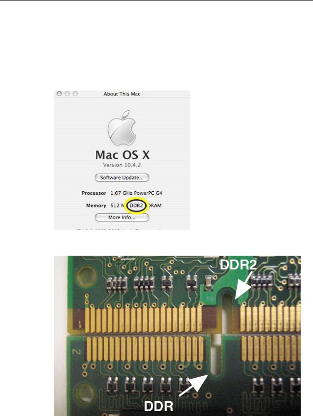
The quickest ways to identify the PowerBook G4 (17-inch Double-Layer SD) computer:
•If the system is bootable, power it on. After pressing the power button the sleep LED light comes on solid and stays on until video appears onscreen.
•Also the "About this Mac." Under Memory, shows DDR2 memory.
• Check a memory card to see if it is DDR2 (keyed differently than DDR)
2 - PowerBook G4 (17-inch DLSD/1.67/1.5/1.33GHz) Basics |
General Information |
Main feature differences from the previous models:
•Higher resolution 17-inch display, 1680 x 1050, 116 dpi (previously 1440 x 900, 100 dpi)
–Prism technology is used to increase the screen brightness from 150 nits to 220 nits
•Support DDR2 memory up to 2GB
•Double-Layer SuperDrive allows user to burn two layers through a single side of a double-layer burnable disk.
•120GB 5400 RPM standard, 100GB 7200 RPM hard drive option
New Parts and Procedures
Service parts and procedures are different from the previous 17-inch PowerBook computer including:
•Top Case
–As the sleep magnet has been relocated to the display bezel, the sleep sensor has moved from the trackpad flex to the edge of the top case. Previous top cases will not work with this system.
•Keyboard
–The keyboard has a narrower flex than the previous the integrated backlight keyboard used in the PowerBook G4 (17-inch 1.67GHz). These two keyboards are not interchangeable. This keyboard is the same as the PowerBook G4 (15-inch Double-Layer SD).
•Mass Storage (Hard drive and optical drive)
–Both devices share a single ATA bus using a cable select addressing scheme. Previously each drive was a master device on separate ATA busses. Although, an older hard drive may work in this system, the optical drive will either not show up as a device or cause the system to not boot-up properly.
•AirPort Extreme and Bluetooth 2.0
–These two functions have been combined on a single card.
–The card has the antenna diversity function built-in, eliminating that card in the clutch barrel.
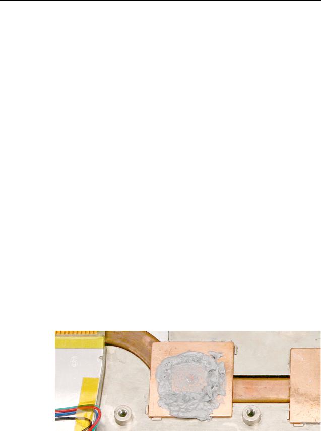
•Main Logic Board
–A new thermal grease is used. It has a greyish color.
General Information |
PowerBook G4 (17-inch DLSD/1.67/1.5/1.33GHz) Basics - 3 |

Flex cable compatibility
Warning: The logic board will be damaged if the wrong sound board or modem flex cable is used. The sound cable marked PowerBook 17" 1.33GHz or greater can NOT be used on the PowerBook G4 (17-inch 1.67GHz) computer. Cables from the earlier PowerBook G4 (17-inch) system are also NOT compatible.
The cables must be marked as indicated in the following chart:
|
PBG4 17" |
|
|
|
|
Double-Layer |
PBG4 17" |
PBG4 17" |
PBG4 17" |
|
SD |
1.67GHz |
1.5GHz |
1.33GHz |
|
|
|
|
|
Sound |
|
PBG4 17" |
PBG4 17" |
PBG4 17" |
Flex |
|
1.67GHz or |
1.33GHz or |
1.33GHz or |
|
N/A |
greater |
greater |
greater |
|
|
|
|
|
Modem |
|
PBG4 17" |
PBG4 17" |
PBG4 17" |
Flex |
|
1.33GHz or |
1.33GHz or |
1.33GHz or |
|
N/A |
greater |
greater |
greater |
|
|
|
|
|
Important Notes
•To disconnect a flex cable connector, if the connector has a plastic film on its top that can be lifted up on one side as a pull tab, carefully pull it and wiggle the connector from side to side to disconnect it. Otherwise carefully rock the connector from side to side, or use a black stick to carefully pry up the connector.
•The AirPort Extreme card assembly has a flex cable glued to the card.
4 - PowerBook G4 (17-inch DLSD/1.67/1.5/1.33GHz) Basics |
General Information |
Tools
The following tools are recommended for the take apart procedures.
•ESD wrist strap and mat
•Soft cloth
•#0 Phillips screwdriver (magnetized)
•#1 Phillips screwdriver (magnetized)
•4 mm socket wrench
•Tweezers (or needlenose pliers)
•Needlenose pliers
•Torx T6 screwdriver
•Torx T8 screwdriver
•Black stick (nylon probe tool 922-5065) (or other nonconductive nylon or plastic flatblade tool)
•Multi-compartment screw tray (such as a plastic ice cube tray)
•Kapton® tape (922-1731 (0.5-inch x 12-yard roll))
•Apple Pro keyboard and mouse (for troubleshooting)
•Small low-power magnet (for troubleshooting)
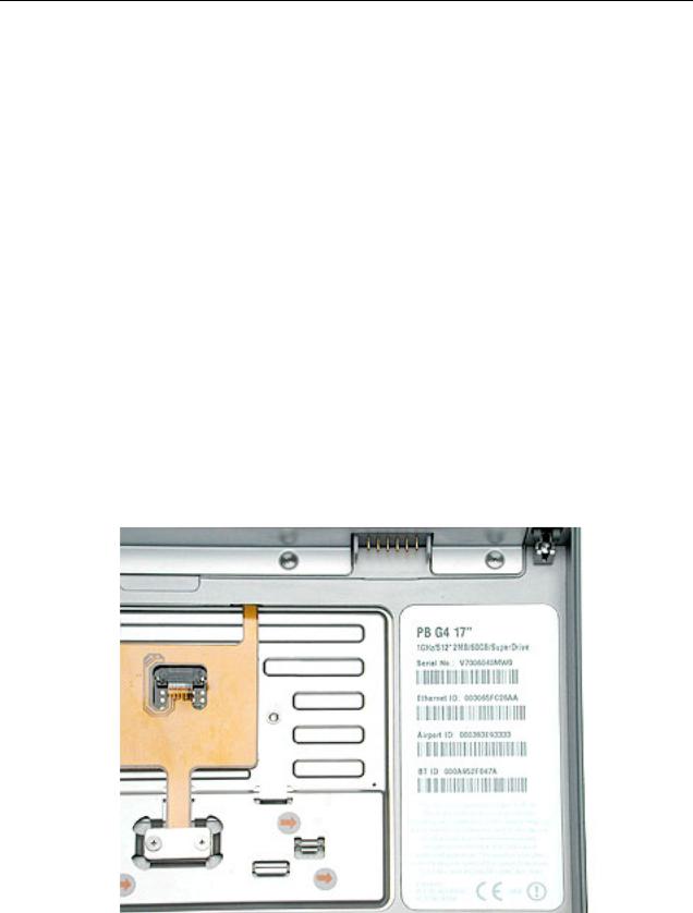
Serial Number Location
The serial number is located in the battery bay.
General Information |
PowerBook G4 (17-inch DLSD/1.67/1.5/1.33GHz) Basics - 5 |

Zero Insertion Force Connectors
Zero insertion force (ZIF) connectors are used in several locations in the computer.
Important: The locking bar on the ZIF connector is extremely fragile and is not intended to separate from the connector. When releasing a bar, use extreme care and a restrained light pressure to move the bar only slightly.
Warning: If a locking bar breaks, you will need to replace the board.
To release the flex cable
Use a flat-blade tool to move the bar on both sides.
6 - PowerBook G4 (17-inch DLSD/1.67/1.5/1.33GHz) Basics |
General Information |

To connect a flex cable
Make sure the locking bar is released, then slide the end of the flex cable all the way into the connector. Hold the cable in place, then slide the locking bar into the connector on both sides to secure.
Important: Verify that the cable is straight. Use either the alignment mark, if present, or the metal edge on the cable as a guide to ensure the cable is straight.
Warning: If the flex cable is inserted crooked, some signals may not be connected or signals may short together (a bad connection is shown below.)
Note: If a cable is not securing properly, verify that it is inserted on the correct side of the locking bar.
General Information |
PowerBook G4 (17-inch DLSD/1.67/1.5/1.33GHz) Basics - 7 |

Service Source
Take Apart
PowerBook G4 (17-inch Double-Layer SD)
PowerBook G4 (17-inch 1.67GHz)
PowerBook G4 (17-inch 1.5GHz)
PowerBook G4 (17-inch 1.33GHz)
© 2005 Apple Computer, Inc. All rights reserved.
Feet
Tools
This procedure requires the following tools:
•Foot kit
•Tweezers or needlenose pliers
•Soft cloth
Preliminary Step
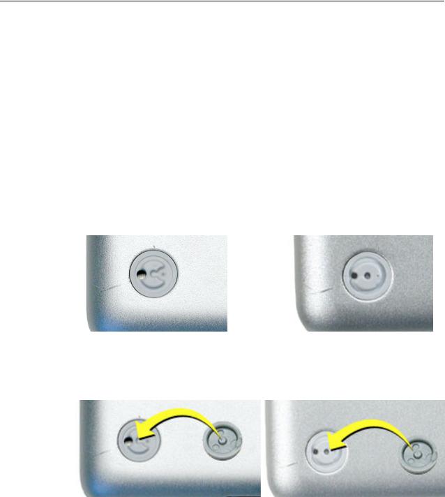
Before you begin, check the bottom case of the computer and compare it with the images in this table. Make sure the foot you want to replace has an intact plug on the bottom case.
|
Plug Area on Bottom Case |
Matching Foot |
Action |
|||||||
|
|
|
|
|
|
|
|
|
|
|
|
Missing plug |
Not available for |
Replace the bottom |
|||||||
|
|
|
|
|
|
|
replacement |
case, or send the |
||
|
|
|
|
|
|
|
||||
|
|
|
|
|
|
|
|
|
|
computer to the Apple |
|
|
|
|
|
|
|
|
|
|
Repair Center for |
|
|
|
|
|
|
|
|
|
|
repair. |
|
|
|
|
|
|
|
|
|
|
|
|
|
|
|
|
|
|
|
|
|
|
|
Plug (either one) |
Foot |
Continue with the |
|||||||
|
|
|
|
|
|
|
|
|
|
procedure, matching |
|
|
|
|
|
|
|
|
|
|
the replacement foot to |
|
|
|
|
|
|
|
|
|
|
either plug on the |
|
|
|
|
|
|
|
|
|
|
bottom case. |
|
|
|
|
|
|
|
|
|
|
|
|
|
|
|
|
|
|
|
|
|
|
|
|
|
|
|
|
|
|
|
|
|
|
|
|
|
|
|
|
|
|
|
|
Feet |
PowerBook G4 (17-inch DLSD/1.67/1.5/1.33GHz) Take Apart - 1 |
Procedure
Warning: The glue used in this procedure can bond instantly to skin. Do not touch the glue. In the event of contact, review the safety instructions at the end of this section. For additional information, refer to the glue manufacturer:
Elmer's Products, Inc.
Columbus, OH. 43215-3799
www.krazyglue.com
1.Place the computer upside down on a clean, lint-free cloth or other nonabrasive surface.
2.Make sure the plug area on the bottom case is clean. If any portion of the soft rubber foot remains, remove it so that only the hard plastic plug is visible (as shown with both types of plugs below).
Important: Notice the recessed hole in the center of the plug. When positioning the foot, make sure the raised bump on the textured plane of the rubber foot fits into the center hole in the plug. This ensures a balanced and level fitting.
|
|
|
|
2 - PowerBook G4 (17-inch DLSD/1.67/1.5/1.33GHz) Take Apart |
Feet |
||
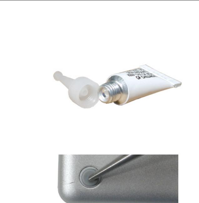
3.Warning: GLUE IS AN EYE AND SKIN IRRITANT. BONDS SKIN INSTANTLY. Do not touch the glue at any time. Before opening the glue, review the safety instructions at the end of this section.
Important: The glue tube included in the kit is sealed until first use. Do not break the seal until you are ready to use the glue. To break the seal, hold the tube upright and away from you. Place the hollow nozzle cap on the tube and tighten it all the way down. The tube is then ready to dispense the glue through the nozzle cap.
4.Apply one drop of glue to the plug on the bottom case. Do not spread the glue.
5.Using tweezers or needlenose pliers, carefully position the new foot so it is centered over the plug, and its integral bumps fit into the compatible holes in the plug.
6.Using the end of the tweezers or pliers—not your finger—lightly press and hold the foot in place for 30 seconds.
7.Before turning over the computer, allow the glue to set for at least 15 minutes.
8.Discard the tube of glue.
SAFETY INSTRUCTIONS: GLUE IS AN EYE AND SKIN IRRITANT. BONDS SKIN INSTANTLY. Contains ethyl cyanoacrylate. Avoid contact with skin and eyes. If eye or mouth contact occurs, hold eyelid or mouth open and rinse thoroughly but gently with water only for 15 minutes and GET MEDICAL ATTENTION. Liquid glue will sting eye temporarily. Solidified glue may irritate eye like a grain of sand and should be treated by an eye doctor. If skin bonding occurs, soak in acetone-based nail polish remover or warm soapy water and carefully peel or roll skin apart (do not pull). Contact through clothing may cause skin burn. If spilled on clothing, flush with cold water. Avoid prolonged breathing of vapors. Use with adequate ventilation. KEEP OUT OF REACH OF CHILDREN.
Feet |
PowerBook G4 (17-inch DLSD/1.67/1.5/1.33GHz) Take Apart - 3 |
Battery
Tools
This procedure requires the following tools:
• Soft cloth
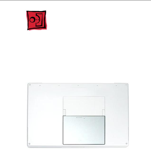
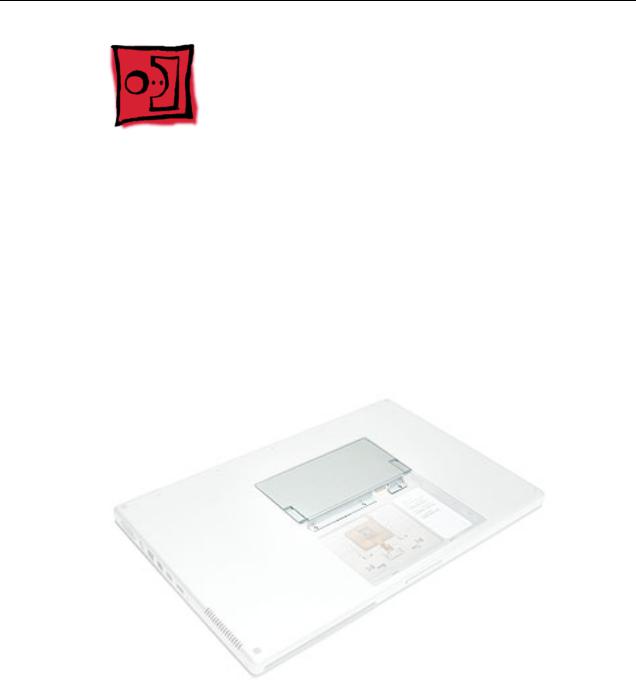
Part Location
Preliminary Steps
Warning: Always shut down the computer before opening it to avoid damaging its internal components or causing injury. After you shut down the computer, the internal components can be very hot. Let the computer cool down before continuing.
4 - PowerBook G4 (17-inch DLSD/1.67/1.5/1.33GHz) Take Apart |
Battery |
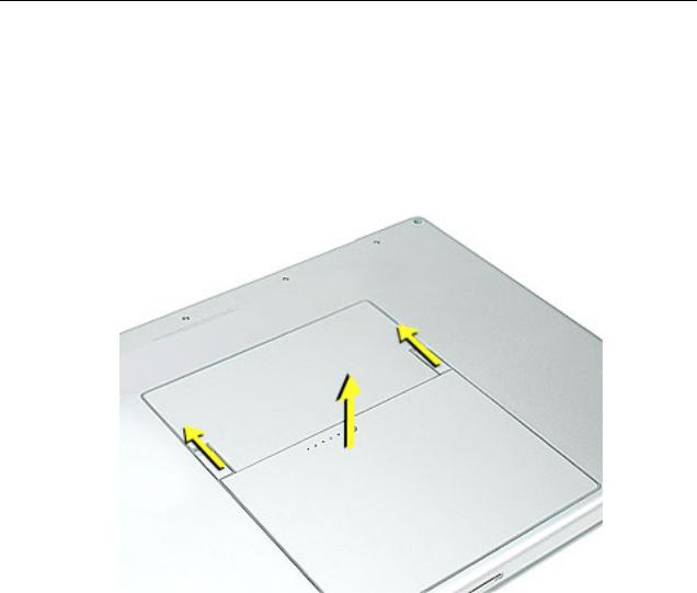
Procedure
1.Shut down the computer.
2.Disconnect the power cord and any other cables connected to the computer.
3.Place the computer face down on a soft cloth.
4.Slide both battery latches away and lift the battery out of the battery bay.
Battery |
PowerBook G4 (17-inch DLSD/1.67/1.5/1.33GHz) Take Apart - 5 |
Memory Door and
Memory Cards
Tools
This procedure requires the following tools:
•Soft cloth
•#0 Phillips screwdriver
Part Location
Preliminary Steps
Before you begin, remove the battery.
6 - PowerBook G4 (17-inch DLSD/1.67/1.5/1.33GHz) Take Apart |
Memory Door and Memory Cards |
Procedure
Warning: If the computer has been recently operating, allow it to cool down before performing this procedure.
1.Place the computer face down on a soft cloth.
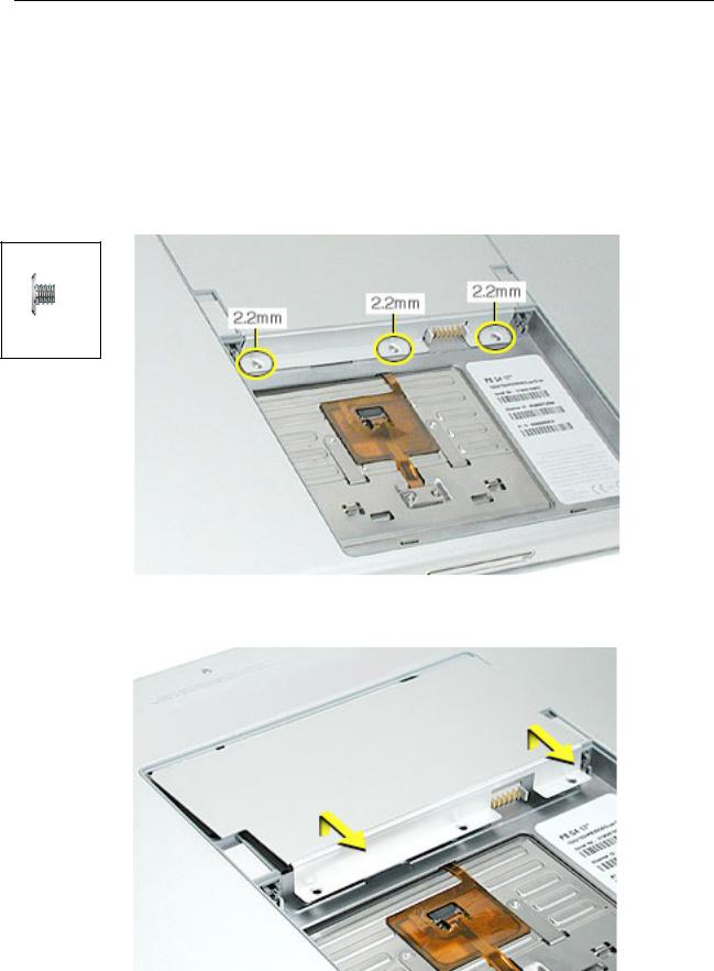
2.Remove the three screws from the memory door.
Note: Check for lost screws caught by magnets inside the front edge of the battery well.
922-5837
Phillips 2.2 mm
3. Lift the memory door up slightly and slide it straight back to remove.
Memory Door and Memory Cards |
PowerBook G4 (17-inch DLSD/1.67/1.5/1.33GHz) Take Apart - 7 |
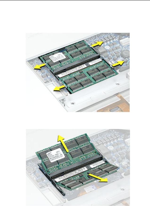
Note: If only one memory card is installed, it’s factory installed in the top memory slot (nearest to outside edge of the computer).
4.To remove either memory card, first release it by spreading apart the tabs in the memory slot from the notches in the card until the card pops up slightly.
5. Pull the card straight out of the memory slot.
8 - PowerBook G4 (17-inch DLSD/1.67/1.5/1.33GHz) Take Apart |
Memory Door and Memory Cards |
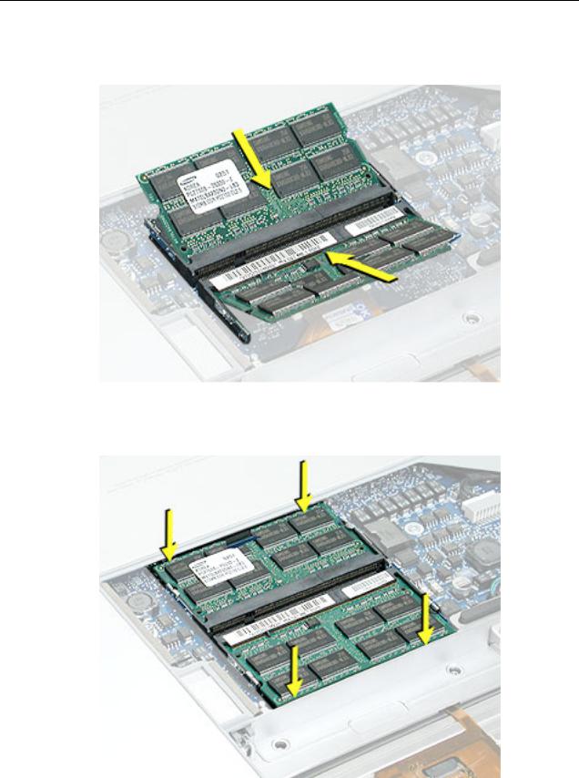
6.Align the notch in the board with the tab in the slot and insert the replacement memory cards at a 30-degree angle, pushing the card firmly until fully seated.
7.Check that the notches in the card clear the tabs as you press down on the sides of the card to lock it into place.
Memory Door and Memory Cards |
PowerBook G4 (17-inch DLSD/1.67/1.5/1.33GHz) Take Apart - 9 |

8.To reinstall the memory door, hold it at a low angle to the battery bay and slide it in under the back edge, then lay it flat. If the door springs up and does not lay flat without tension, remove it and reinstall at a lower angle.
9.Install the memory door screws.
Note: Before securing, check that the door edge rests flush and inside the ridge.
10.Replace the battery.
11.Use Apple System Profiler to verify that the memory is recognized. (Choose the menu bar Apple logo ( ) > About This Mac, click More Info..., select the System Profile tab, open the Memory Overview.)
10 - PowerBook G4 (17-inch DLSD/1.67/1.5/1.33GHz) Take Apart |
Memory Door and Memory Cards |
Top Case
Tools
This procedure requires the following tools:
•#0 Phillips screwdriver (magnetized)
•#1 Phillips screwdriver (magnetized)
•Torx T8 screwdriver (magnetized)
•Black stick (or other nonconductive nylon or plastic flat-blade tool)
•Soft cloth
•Multi-compartment screw tray (21 screws to remove the top case)
Part Location
Top Case |
PowerBook G4 (17-inch DLSD/1.67/1.5/1.33GHz) Take Apart - 11 |
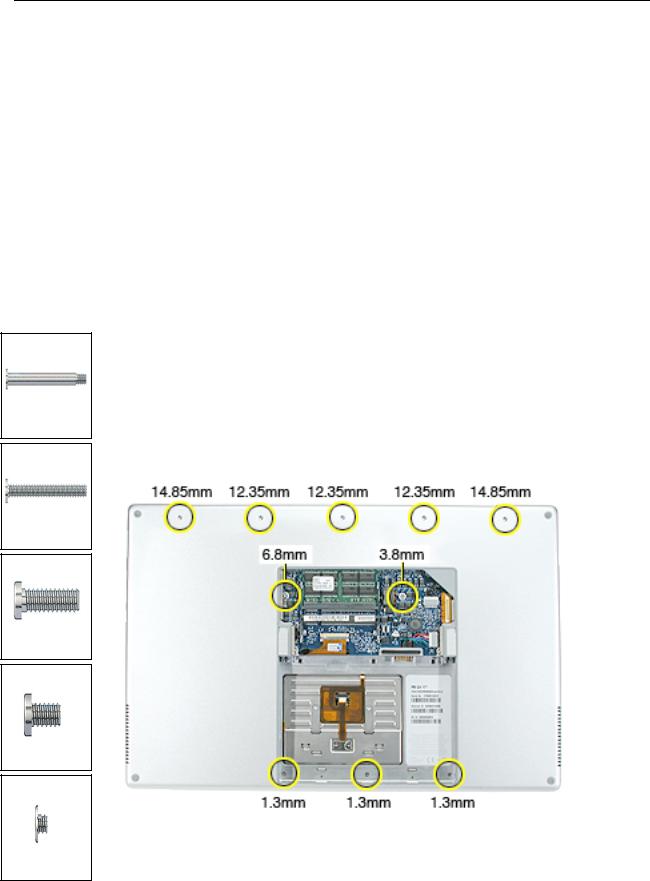
076-0998
Phillips 14.85 mm
076-0998
Phillips 12.35 mm
922-5842
Torx 6.8 mm
922-5839
Torx 3.8 mm
076-0998
Phillips 1.3 mm
Preliminary Steps
Before you begin, remove the following:
•Battery
•Memory door
•Lower memory card (nearest to battery bay), if present
Procedure
Note: This procedure removes the top case and keyboard assembly. The keyboard is attached to the top case and is not removed.
1.Place the computer face down on a soft cloth.
2.Remove the three screws inside the battery bay.
Note: These screws are shorter than on the memory door. Use care not to lose the screws into holes along the battery bay.
Note: Check for lost screws caught by magnets inside the front edge of the battery well.
3.Remove the five screws along the back edge (the two outside screws are longer and have “shoulders”).
4.Remove the two screws on the logic board
12 - PowerBook G4 (17-inch DLSD/1.67/1.5/1.33GHz) Take Apart |
Top Case |

5.Locate the top case flex cable and ZIF connector.
Note: On the PowerBook G4 (17-inch 1.67GHz), the flex cable is narrower.
6.Very carefully disconnect and remove the cable from the connector.
Important: The ZIF connector and locking bar are fragile and can easily break if too much force is used. (See “Zero Insertion Force Connectors” heading.)
Top Case |
PowerBook G4 (17-inch DLSD/1.67/1.5/1.33GHz) Take Apart - 13 |
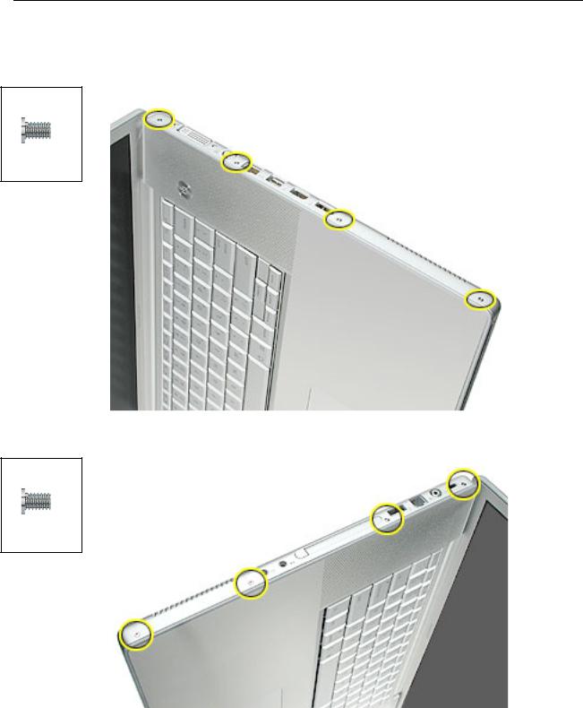
7.Open the display and place the computer on its side.
8.Remove four side screws from both sides.
076-0998
Phillips 3.4 mm
076-0998
Phillips 3.4 mm
14 - PowerBook G4 (17-inch DLSD/1.67/1.5/1.33GHz) Take Apart |
Top Case |
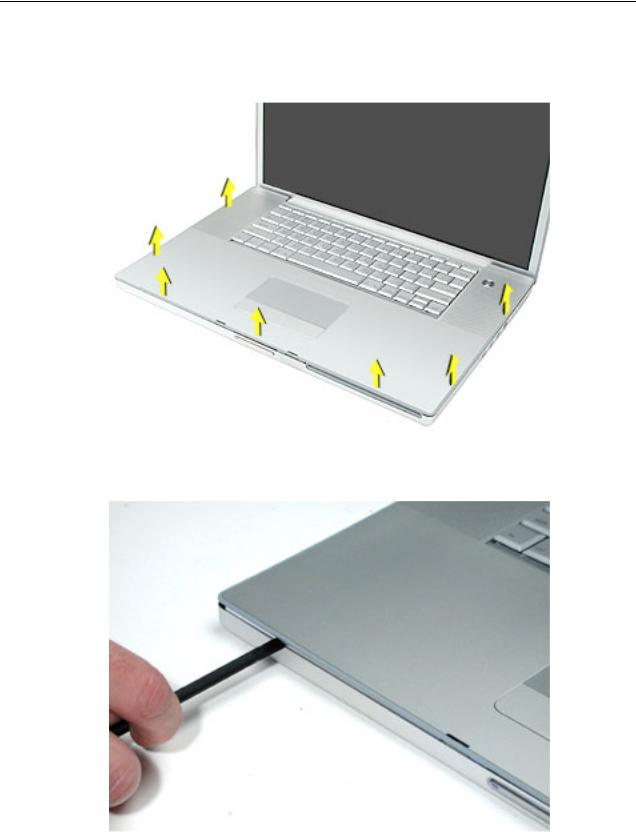
9.Turn the computer over.
10.Pull up on the top case along the sides and front until it releases.
Note: A black stick inserted and twisted under the top case seam may be helpful.
Top Case |
PowerBook G4 (17-inch DLSD/1.67/1.5/1.33GHz) Take Apart - 15 |
Replacement Procedure
Note: If replacing the top case, remove the keyboard and transfer it to the replacement top case.
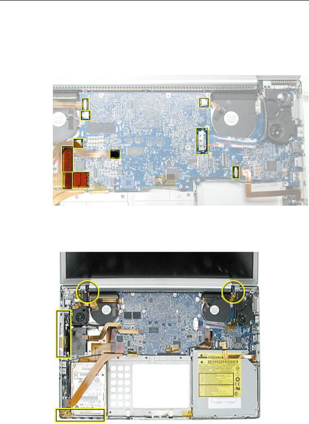
1.Visually check to verify that all cables (highlighted below) are connected and routed correctly with nothing raised up or incorrectly over a component.
2.Check perimeter wiring, where shown, to verify that it will not be caught or pinched by the top case during replacement.
16 - PowerBook G4 (17-inch DLSD/1.67/1.5/1.33GHz) Take Apart |
Top Case |
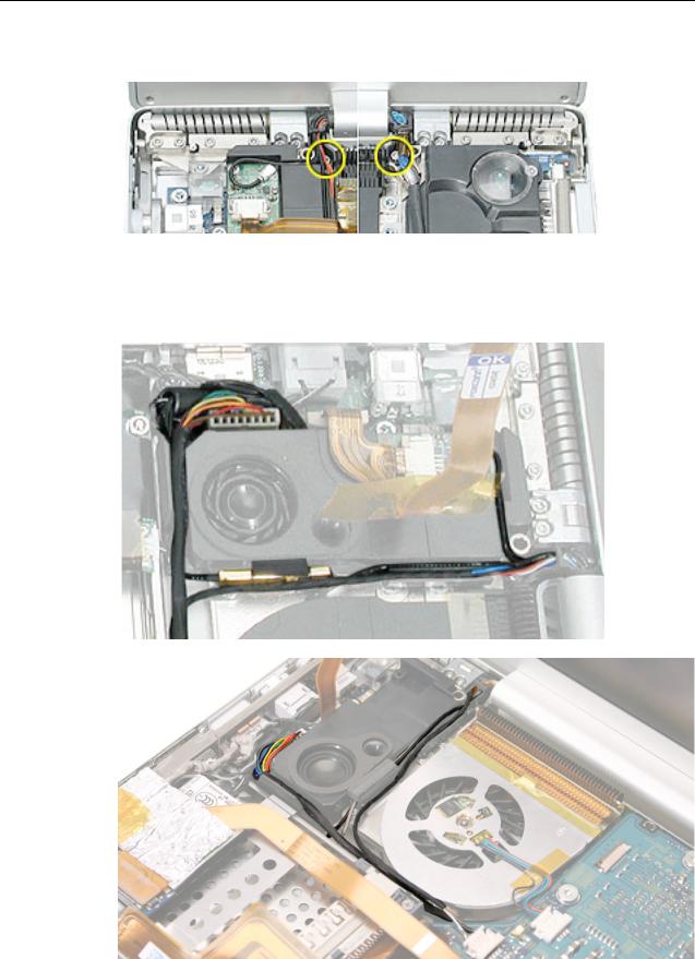
3. Check that display cable brackets are properly seated and secured with screws.
4.Verify that cables for Bluetooth, AirPort Extreme, inverter and power cable from the DC-in board are routed and seated correctly in channels around the left speaker.
See PowerBook G4 (17-inch Double-Layer SD) cable routing, below.
Top Case |
PowerBook G4 (17-inch DLSD/1.67/1.5/1.33GHz) Take Apart - 17 |
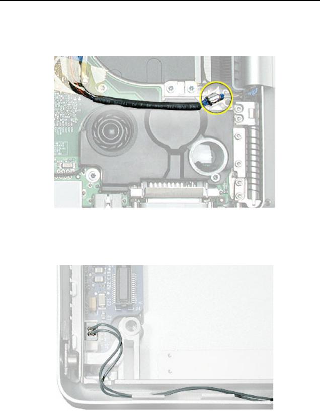
5.Verify that the LVDS cable’s bead fits into the metal channel (rounded side up so that its teeth secure it) and that the cable is secured into the channel along the right speaker.
6.Verify that the sleep LED wires route over the notch in the frame (secure with Kapton tape) and along the inside channel away from the front edge so that it will not be damaged when replacing the top case.
18 - PowerBook G4 (17-inch DLSD/1.67/1.5/1.33GHz) Take Apart |
Top Case |
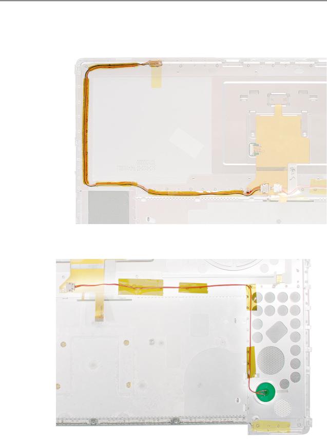
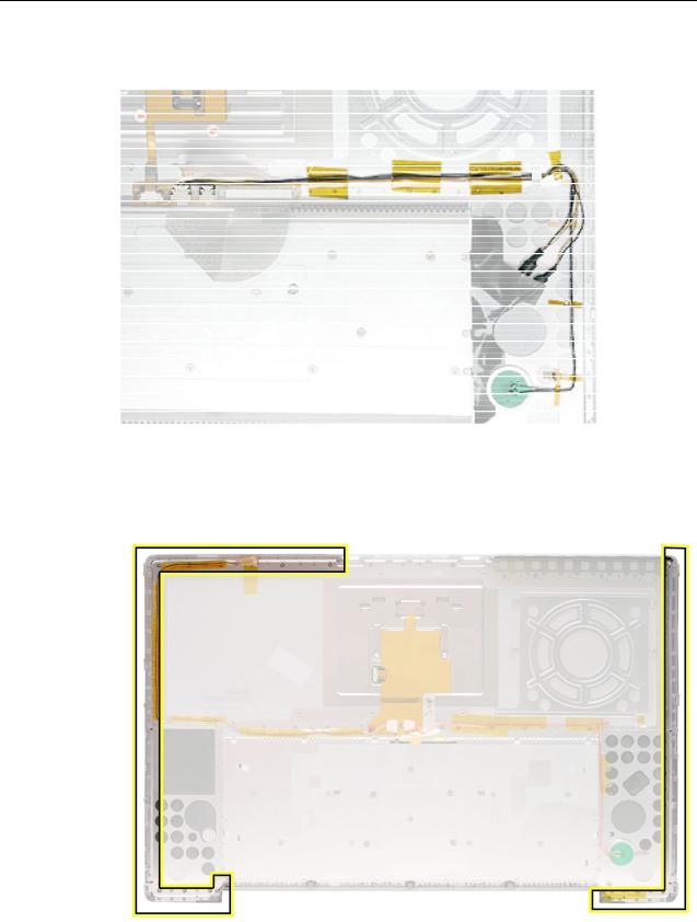
7.On the top case, check cable connections and routing.
PowerBook G4 (17-inch Double-Layer SD):
PowerBook G4 (17-inch Double-Layer SD) and (17-inch 1.67GHz):
Top Case |
PowerBook G4 (17-inch DLSD/1.67/1.5/1.33GHz) Take Apart - 19 |
PowerBook G4 (17-inch 1.5GHz) and (17-inch 1.33GHz):
8.Check that the perimeter metal tabs are not bent.
Note: Do not bend the tabs; the metal quickly fatigues and can break off easily.
20 - PowerBook G4 (17-inch DLSD/1.67/1.5/1.33GHz) Take Apart |
Top Case |
 Loading...