

Page 1

Service Source
PowerBook G4 (DVI)
Updated 4 December 2003
© 2003 Apple Computer, Inc. All rights reserved.
Page 2
Service Source
Upgrades
PowerBook G4 (DVI)
© 2003 Apple Computer, Inc. All rights reserved.
Page 3
PowerBook G4 (DVI)
Check for PowerBook G4 (DVI) 867 MHz Upgrade
Check for Upgraded Computer
Before you begin service procedures, check whether the computer has been upgraded
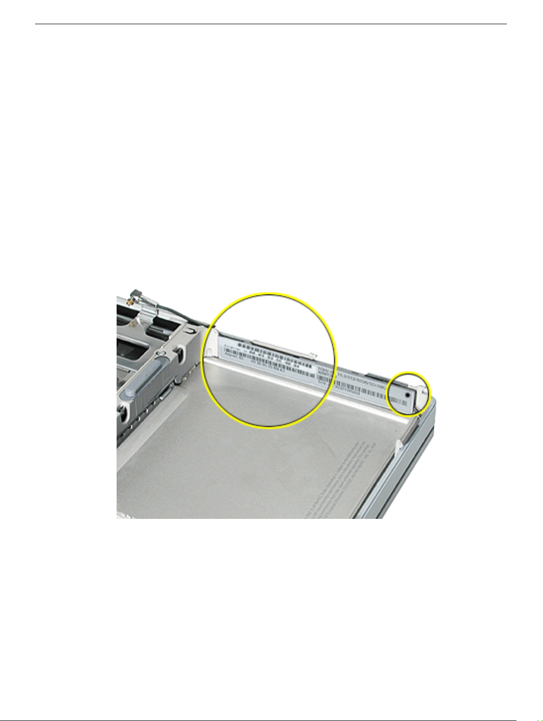
with a PowerBook G4 (DVI) 867 MHz Upgrade Kit. Look at the computer’s ID label in the
battery well to see if there is an Ethernet bar code label over the original Ethernet bar
code, and a black dot in the upper right corner of the ID label.
In addition, the customer may also have a “Proof of Repair and Upgrade” sheet.
If so, the computer has been upgraded with a PowerBook G4 (DVI) 867 MHz Upgrade Kit.
The upgraded computer uses the following PowerBook G4 (1GHz/867MHz) parts:
• 867MHz logic board (661-1799)
• DC-in board (922-5460)
• Heat exchanger (922-5445)
• Primary fan (922-5459)
• Secondary fan (922-5564)
Use only these parts, and refer to the PowerBook G4 (1GHz/867MHz) service manual
(Updated 8 August 2003, or later) when performing service involving these parts.
Note:
This computer upgrade is NOT available to service providers.
2003 Apple Computer, Inc. All rights reserved. Updated: 14 October 2003
©
Page 4

PowerBook G4 (DVI)
Heat Exchanger Upgrade
Installation Instructions
The following instructions explain how to install the appropriate parts of the Heat
Exchanger Upgrade Kit (076-1071) in the PowerBook G4 (DVI) computer.
Important:
exceptions are shown in this chapter. Perform these “exception” procedures at the
appropriate points, and ignore the take apart procedures that do not apply.
Important:
to the “Check for PowerBook G4 (DVI) 867 MHz Upgrade” chapter of this manual to check
for this computer upgrade.
Important:
(667 MHz and 800 MHz). Verify the configuration and follow the procedures below:
Note:
Verify that the kit contains the following:
• New version heat exchanger with ribbed extension
• Heat exchanger hold down bracket
• New version secondary fan (for 800 MHz units, only)
• (1) thick and (1) thin washer (for 667 MHz units, only)
Note:
Use this chapter in conjunction with the take apart chapters. Only the
This kit is NOT for PowerBook G4 (DVI) 867 MHz upgraded computers. Refer
Some parts and procedures are different depending upon the configuration
The kit consists of parts for both the 667 MHz and 800 MHz configurations.
Kapton® tape is needed for the 667 MHz configuration and is not included in the kit.
2003 Apple Computer, Inc. All rights reserved.
©
Updated: 4 December 2003
Page 5
Procedure
For both configurations:
1. Remove the old heat exchanger and the secondary fan bracket (with fan, if present).
2. Install the new heat exchanger from the kit.
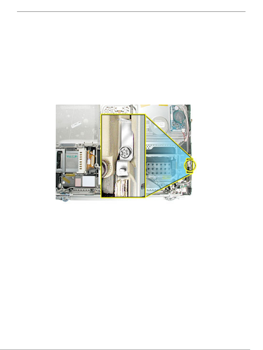
3. Install the heat exchanger hold-down bracket, as shown here. Use the screw that was
removed from the rib frame at this location.
Replacement Note:
that the ribs on the heat exchanger do not block the vents.
Important:
on the new heat exchanger, and that all residual thermal material is removed from the
logic board CPU chip, if any.
Before installing the logic board, verify that all thermal materials are installed
Look from the side through the air vents of the top case to verify
Important:
install thermal material onto the logic board chip.
If the heat exchanger has thermal material installed for the CPU chip, do not
PowerBook G4 (DVI) Heat Exchanger Upgrade -
2
Page 6
For the 667 MHz configuration
This configuration does not use a secondary fan or bracket. A thin and thick washer will be
installed.
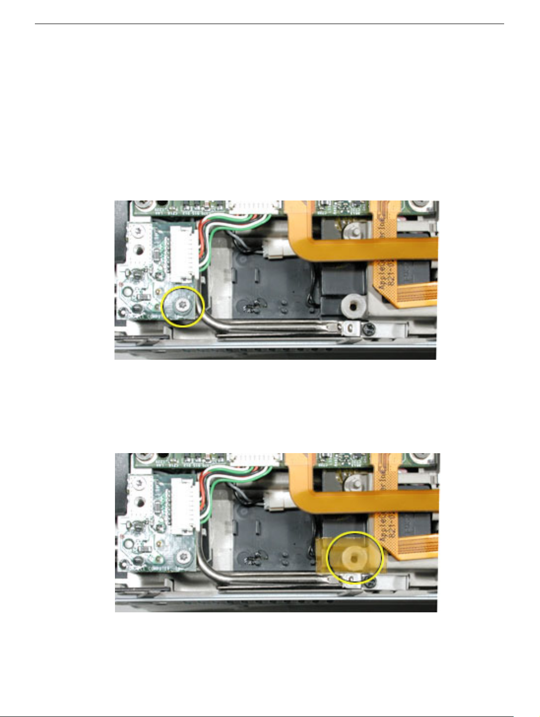
1. With the screw removed from the DC-in board, center the thin washer over the screw
hole in the board, then replace the screw, as shown.
Replacement Note:
The unplugged adapter connector may be inserted onto the DC connector to ensure that the
connector is centered and straight before securing the DC-in board.
2. Center the thick washer over the screw hole shown below (this is a bottom case screw
hole) and place Kapton tape over the top to secure it in place.
Important:
Make sure the DC connector is straight and centered in the port opening.
Verify that the washer does not obstruct the screw hole.
PowerBook G4 (DVI) Heat Exchanger Upgrade -
3
Page 7
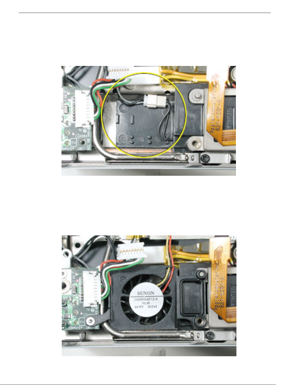
For the 800 MHz configuration
This configuration uses the new secondary fan included in the kit.
1. Reroute the speaker wire and connector, as shown.
2. Install the secondary fan, as shown.
Replacement Note:
The unplugged adapter connector may be inserted onto the DC connector to ensure that the
connector is centered and straight before securing the fan to the DC-in board.
Make sure the DC connector is straight and centered in the port opening.
PowerBook G4 (DVI) Heat Exchanger Upgrade -
4
Page 8

Service Source
Take Apart
PowerBook G4 (DVI)
© 2003 Apple Computer, Inc. All rights reserved.
Page 9

PowerBook G4 (DVI)
Keyboard
Replacement Instructions
Follow the instructions in this sheet carefully. Failure to follow these instructions could
damage your equipment and void its warranty.
Note:
Written and video instructions covering customer-installable parts are available at
http://www.info.apple.com/installparts/.
Warning: During this procedure, keep small parts away from children.
Tools Required
The only tool required for this procedure is a jeweler’s flat-blade screwdriver
(if keyboard is locked).
Removing the Installed Keyboard
Warning: Always shut down your computer before opening it to avoid damaging its
internal components or causing injury. After you shut down the computer, the
internal components can be very hot. Let the computer cool down before
continuing.
1. Place your computer on a clean, flat surface.
2. Shut down your computer and wait thirty minutes before continuing.
3. Disconnect the power cord and any other cables connected to the computer.
Page 10
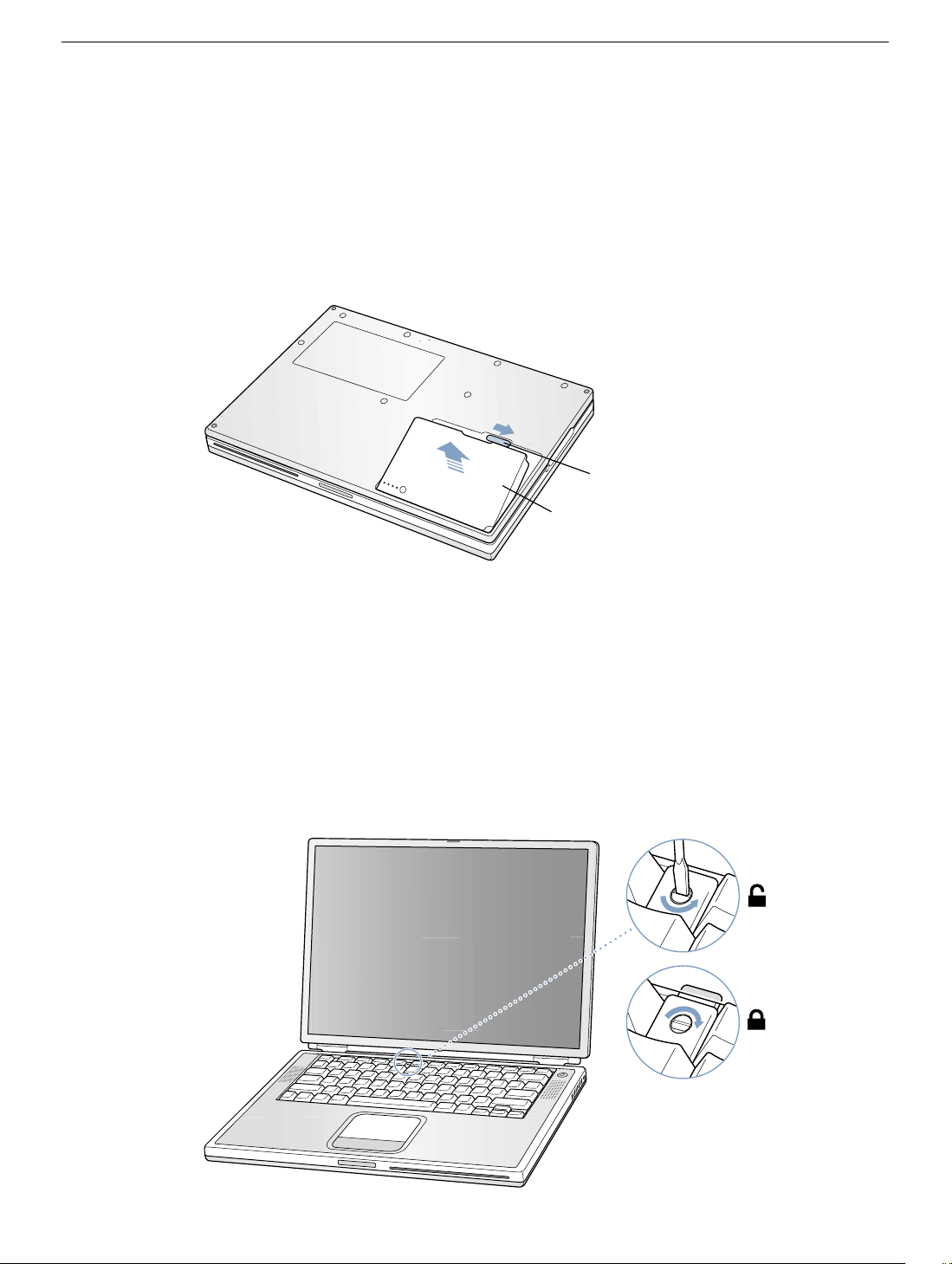
4. Close the computer and turn it over.
5. Slide the battery latch
(Figure 1A)
to the right to remove the battery
(Figure 1B)
Removing the battery will prevent you from accidentally turning on the computer.
Warning: Removing the battery before shutting down your computer may
result in data loss.
Figure 1
A
B
6. Turn over the computer.
7. Raise the display so you can access the keyboard.
.
8. Make sure the keyboard locking screw, located in the small plastic tab to the left of the
Num Lock key
(Figure 2)
, is not in the locked position. Your PowerBook comes with
the keyboard unlocked, so unless you or someone else locked the keyboard, you can
skip this step.
To unlock the keyboard, turn the screw 1/2 turn.
Figure 2
PowerBook G4 (DVI) Keyboard -
2
Page 11
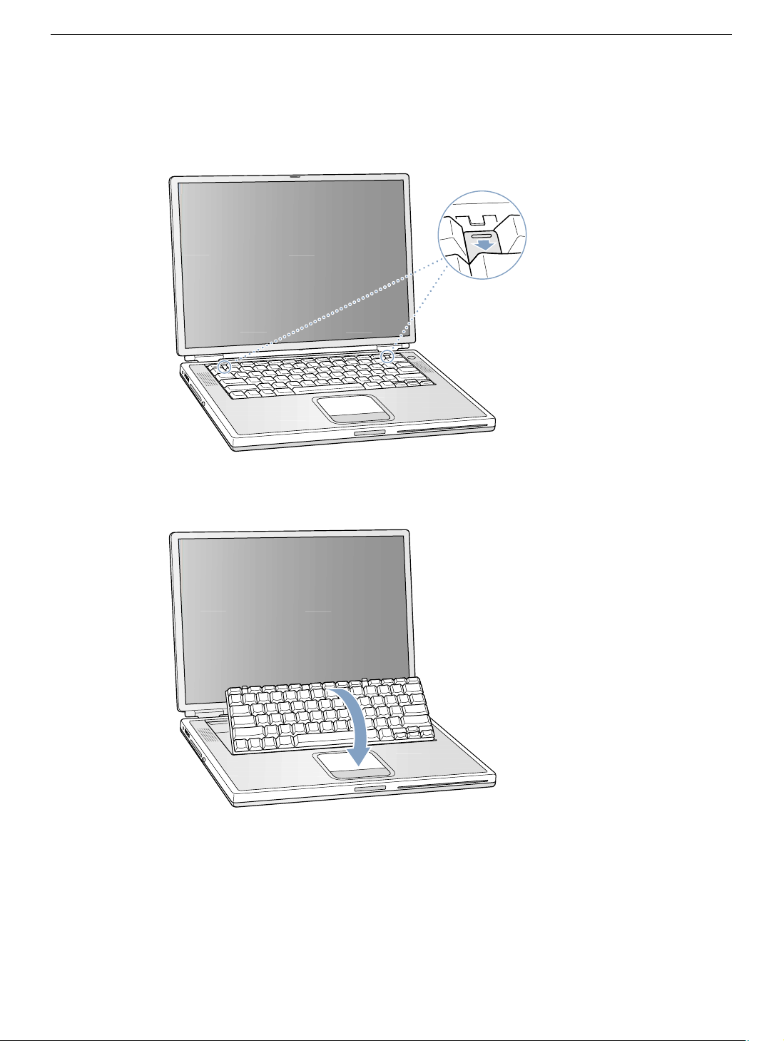
9. Release the keyboard by pulling down on the keyboard release tabs (located to the left
of the F1 and F12 keys)
(Figure 3)
, then lift the top portion of the keyboard up slightly,
and toward the display.
Figure 3
®
10. Flip the keyboard over and lay it on the palm rests and trackpad.
Figure 4
(Figure 4)
PowerBook G4 (DVI) Keyboard -
3
Page 12
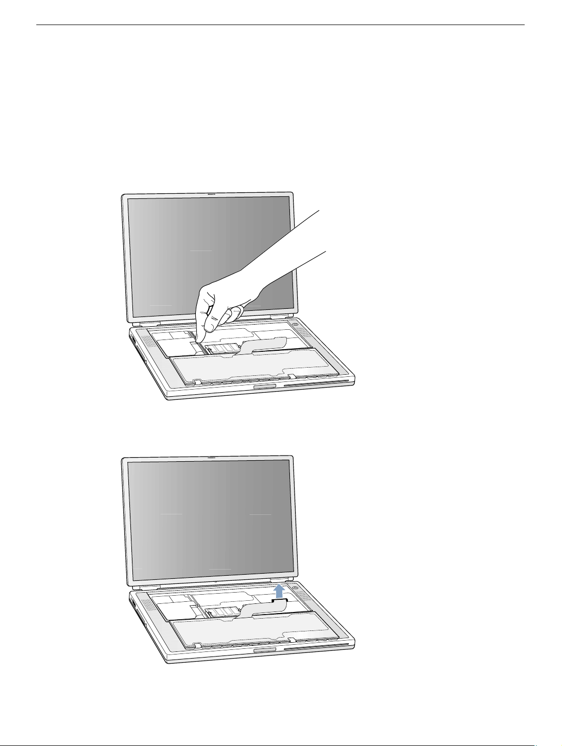
11. Touch the computer’s inside framework (a dull gray conductive composite material) to
discharge any static electricity, as shown
(Figure 5)
.
Important:
touching the computer’s framework before you touch any parts or install any
components inside the computer. To avoid static electricity building back up in your
body, do not walk around the room until you have completed your installation and
closed the computer.
Figure 5
To avoid electrostatic discharge damage, always ground yourself by
12. Locate the keyboard cable connector.
Figure 6
13. Pull up on the connector, from side to side if needed, to disconnect it from the computer.
14. Set the keyboard aside.
(Figure 6)
PowerBook G4 (DVI) Keyboard -
4
Page 13
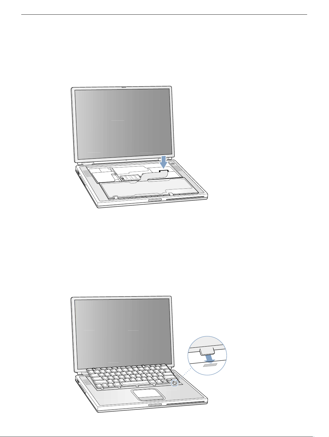
Installing the Replacement Keyboard
1. Lay the replacement keyboard in the correct orientation over the keyboard opening,
then flip it toward you and lay it face down on the palm rests and trackpad to expose its
connector cable.
Figure 7
(Figure 7)
2. Firmly insert the keyboard cable connector into its connector on the computer.
3. Flip the keyboard back toward the keyboard opening in the case.
4. Hold the keyboard at an angle above the keyboard opening, and insert the tabs on the
bottom edge of the keyboard into the slots below the edge of the opening.
Important:
against the edge of the opening.
Figure 8
Make sure that all the tabs are seated and that the keyboard rests flush
(Figure 8)
PowerBook G4 (DVI) Keyboard -
5
Page 14
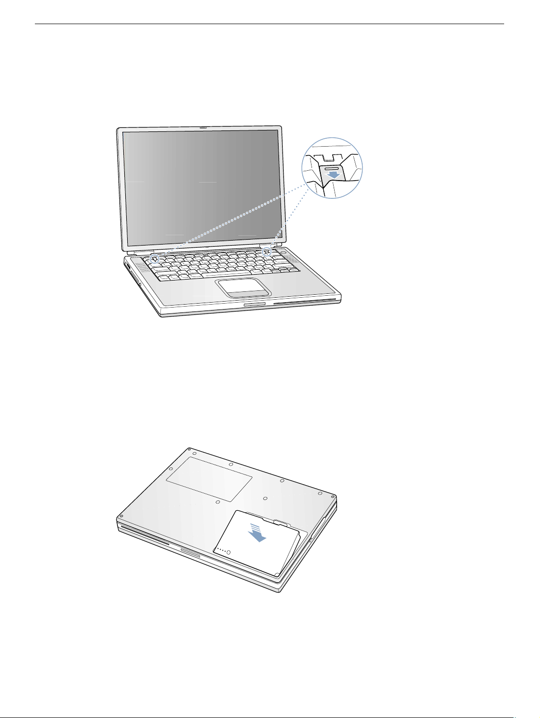
5. Lay the keyboard flat into the keyboard opening.
6. Pull down on the keyboard release tabs and then press down on the top portion of the
keyboard.
(Figure 9)
Figure 9
®
7. Release the tabs to secure the keyboard in place.
8. Close the display and turn the PowerBook over.
9. Replace the battery into the battery compartment.
Important:
Make sure that the battery locks securely into place and that the battery
(Figure 10)
latch is slid all the way into the locked position.
Figure 10
10. Reconnect the power cord and any other cables that were connected, and restart your
computer.
Warning: Never turn on your computer unless all of its internal and external
parts are in place and it is closed. Operating the computer when it is open or
missing parts can damage your computer or cause injury.
PowerBook G4 (DVI) Keyboard -
6
Page 15

Apple Computer, Inc.
© 2002 Apple Computer, Inc. All rights reserved.
This document is protected under U.S. Copyright Law and International Treaties, and no
part of this document may be reproduced in any form without written permission from
Apple.
Apple is not responsible for typographical, printing, or inadvertent errors.
Apple Computer, Inc.
1 Infinite Loop
Cupertino, CA 95014-2084
USA
+ 1 408 996 1010
http://www.apple.com
Apple, the Apple logo, and PowerBook are trademarks of Apple Computer, Inc., registered
in the U.S. and other countries.
PowerBook G4 (DVI) Keyboard -
7
Page 16

PowerBook G4 (DVI)
Memory Card
Replacement Instructions
Follow the instructions in this sheet carefully. Failure to follow these instructions could
damage your equipment and void its warranty.
Note:
Written and video instructions covering customer-installable parts are available at
http://www.info.apple.com/installparts/.
Warning: During this procedure, keep small parts away from children.
Tools Required
The only tool required for this procedure is a jeweler’s flat-blade screwdriver
(if keyboard is locked).
Opening the Computer
Warning: Always shut down your computer before opening it to avoid damaging its
internal components or causing injury. After you shut down the computer, the
internal components can be very hot. Let the computer cool down before
continuing.
1. Place your computer on a clean, flat surface.
2. Shut down your computer and wait thirty minutes before continuing.
3. Disconnect the power cord and any other cables connected to the computer.
Page 17
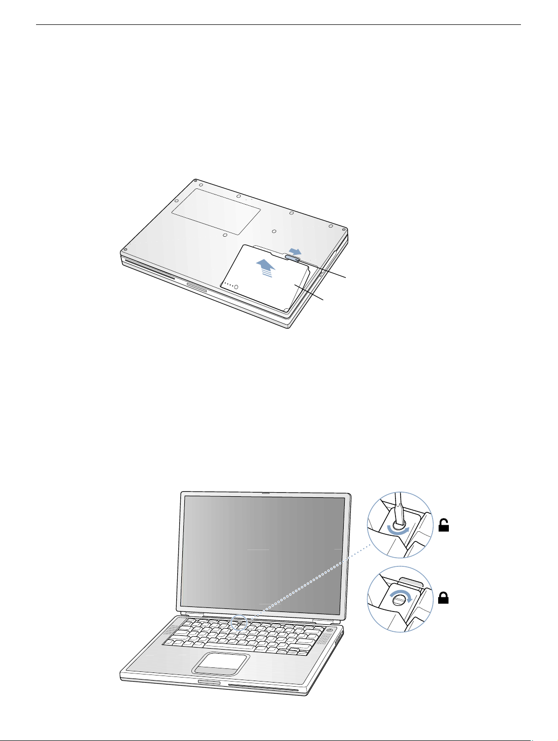
4. Close the computer and turn it over.
5. Slide the battery latch
(Figure 1A)
to the right to remove the battery
(Figure 1B)
Removing the battery will prevent you from accidentally turning on the computer.
Warning: Removing the battery before shutting down your computer may
result in data loss.
Figure 1
A
B
6. Turn over the computer.
7. Raise the display so you can access the keyboard.
.
8. Make sure the keyboard locking screw, located in the small plastic tab to the left of the
Num Lock key
(Figure 2)
, is not in the locked position. Your PowerBook comes with
the keyboard unlocked, so unless you or someone else locked the keyboard, you can
skip this step.
To unlock the keyboard, turn the screw 1/2 turn.
Figure 2
PowerBook G4 (DVI) Memory -
2
Page 18
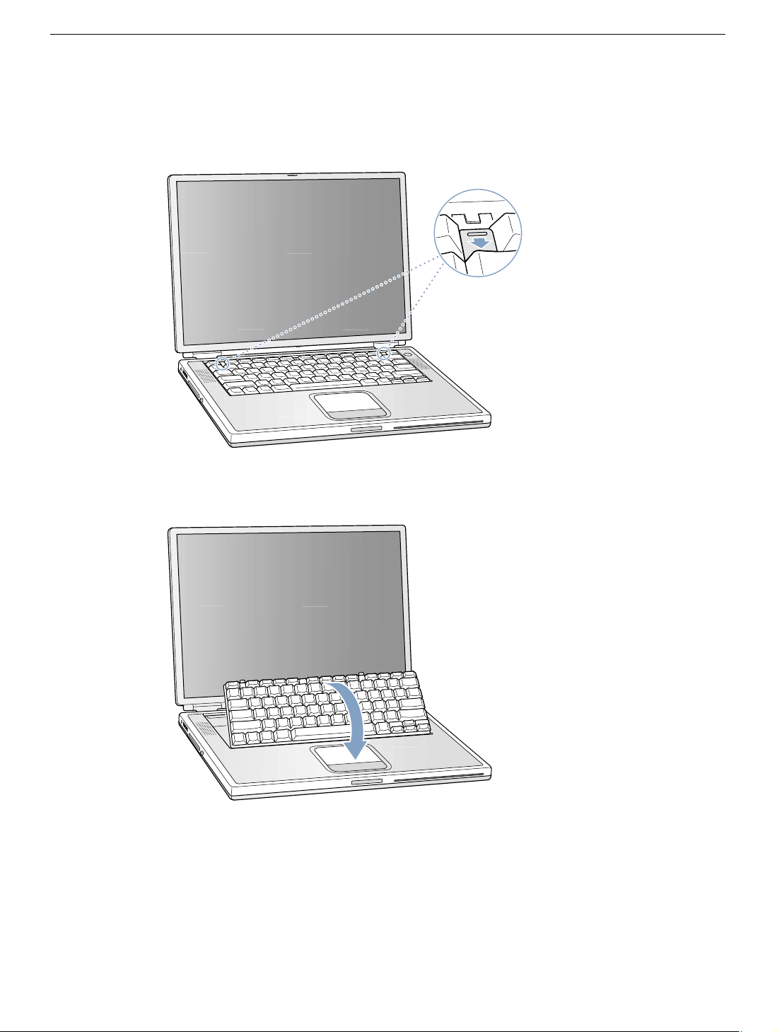
9. Release the keyboard by pulling down on the keyboard release tabs (located to the left
of the F1 and F12 keys)
(Figure 3)
, then lift the top portion of the keyboard up slightly,
and toward the display.
Figure 3
®
10. Flip the keyboard over and lay it on the palm rests and trackpad.
Figure 4
(Figure 4)
PowerBook G4 (DVI) Memory -
3
Page 19
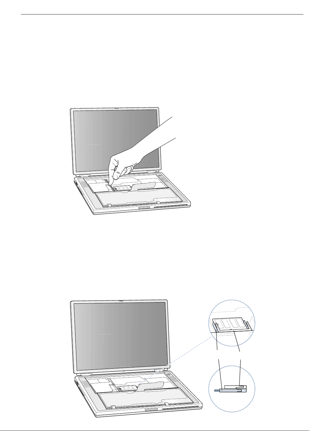
11. Touch the computer’s inside framework (a dull gray conductive composite material) to
discharge any static electricity, as shown (Figure 5).
Important: To avoid electrostatic discharge damage, always ground yourself by
touching the computer’s framework before you touch any parts or install any
components inside the computer. To avoid static electricity building back up in your
body, do not walk around the room until you have completed your installation and
closed the computer.
Figure 5
Removing the Installed Memory Card
1. To remove a memory card, locate the brackets that secure the card on both sides
(Figure 6). Carefully spread the brackets apart until the card releases on each side.
Pull the card up and out.
Note: If there is a memory card in the upper memory slot (Figure 6A), it must be
removed before removing a card in the lower slot (Figure 6B).
Figure 6
B
A
PowerBook G4 (DVI) Memory - 4
Page 20
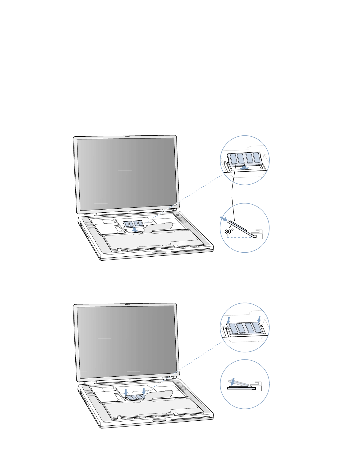
Installing the Replacement Memory Card
Warning: When handling a memory card, do not touch its gold connectors. Handle
the card only by the edges.
1. To install the memory card, line up the notch in the card with the small tab in the
memory slot. Hold the card at a 30-degree angle (Figure 7A), and then push the card
into the slot until it is firmly seated.
Note: You may feel some resistance. If you are having trouble inserting the card, try
pushing one side at a time.
Figure 7
A
2. Gently push the card down until the two brackets on either side of the card lock into
place (Figure 8).
Figure 8
PowerBook G4 (DVI) Memory - 5
Page 21
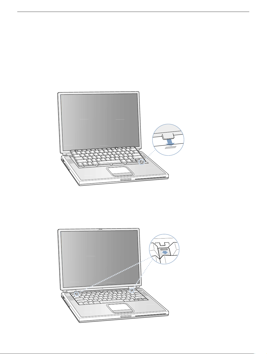
Closing the Computer
1. Flip the keyboard back toward the keyboard opening in the case.
2. Hold the keyboard at an angle above the keyboard opening, and insert the tabs on the
bottom edge of the keyboard into the slots below the edge of the opening. (Figure 9)
Important: Make sure that all the tabs are seated and that the keyboard rests flush
against the edge of the opening.
Figure 9
3. Lay the keyboard flat into the keyboard opening.
4. Pull down on the keyboard release tabs and then press down on the top portion of the
keyboard. (Figure 10)
Figure 10
®
5. Release the tabs to secure the keyboard in place.
PowerBook G4 (DVI) Memory - 6
Page 22
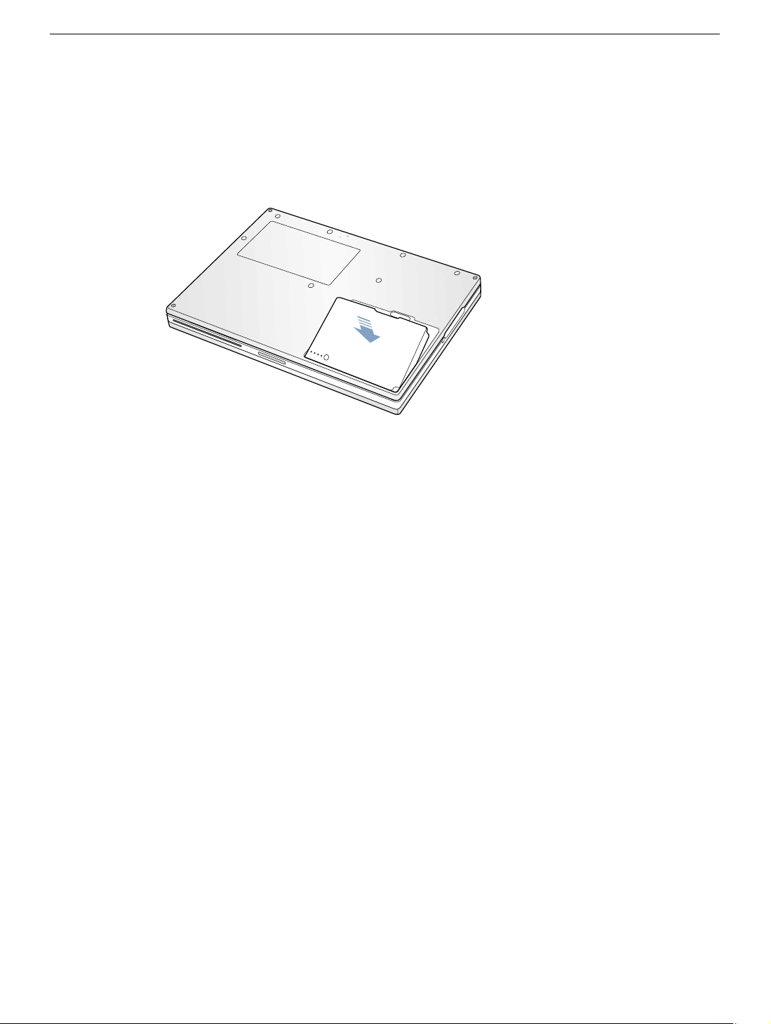
6. Close the display and turn the PowerBook over.
7. Replace the battery into the battery compartment. (Figure 11)
Important: Make sure that the battery locks securely into place and that the battery
latch is slid all the way into the locked position.
Figure 11
8. Reconnect the power cord and any other cables that were connected, and restart your
computer.
Warning: Never turn on your computer unless all of its internal and external
parts are in place and it is closed. Operating the computer when it is open or
missing parts can damage your computer or cause injury.
Apple Computer, Inc.
© 2002 Apple Computer, Inc. All rights reserved.
This document is protected under U.S. Copyright Law and International Treaties, and no
part of this document may be reproduced in any form without written permission from
Apple.
Apple is not responsible for typographical, printing, or inadvertent errors.
Apple Computer, Inc.
1 Infinite Loop
Cupertino, CA 95014-2084
USA
+ 1 408 996 1010
http://www.apple.com
Apple, the Apple logo, and PowerBook are trademarks of Apple Computer, Inc., registered
in the U.S. and other countries.
PowerBook G4 (DVI) Memory - 7
Page 23

PowerBook G4 (DVI)
Bottom Case
Replacement Instructions
Follow the instructions in this sheet carefully. Failure to follow these instructions could
damage your equipment and void its warranty.
Note: Written and video instructions covering customer-installable parts are available at
http://www.info.apple.com/installparts/.
Warning: Sharp edges can exist inside your computer and on any parts being
removed or installed. Use caution to avoid injury. Keep small parts away from
children.
Tools Required
• Soft towel or cloth, larger than the PowerBook
• Torx T8 screwdriver (provided with bottom case)
Removing the Bottom Case
Warning: Always shut down your computer before opening it to avoid damaging its
internal components or causing injury. After you shut down the computer, the
internal components can be very hot. Let the computer cool down before
continuing.
1. Place your computer on a clean, flat surface.
2. Shut down your computer and wait thirty minutes before continuing.
3. Disconnect the power cord and any other cables connected to the computer.
Page 24
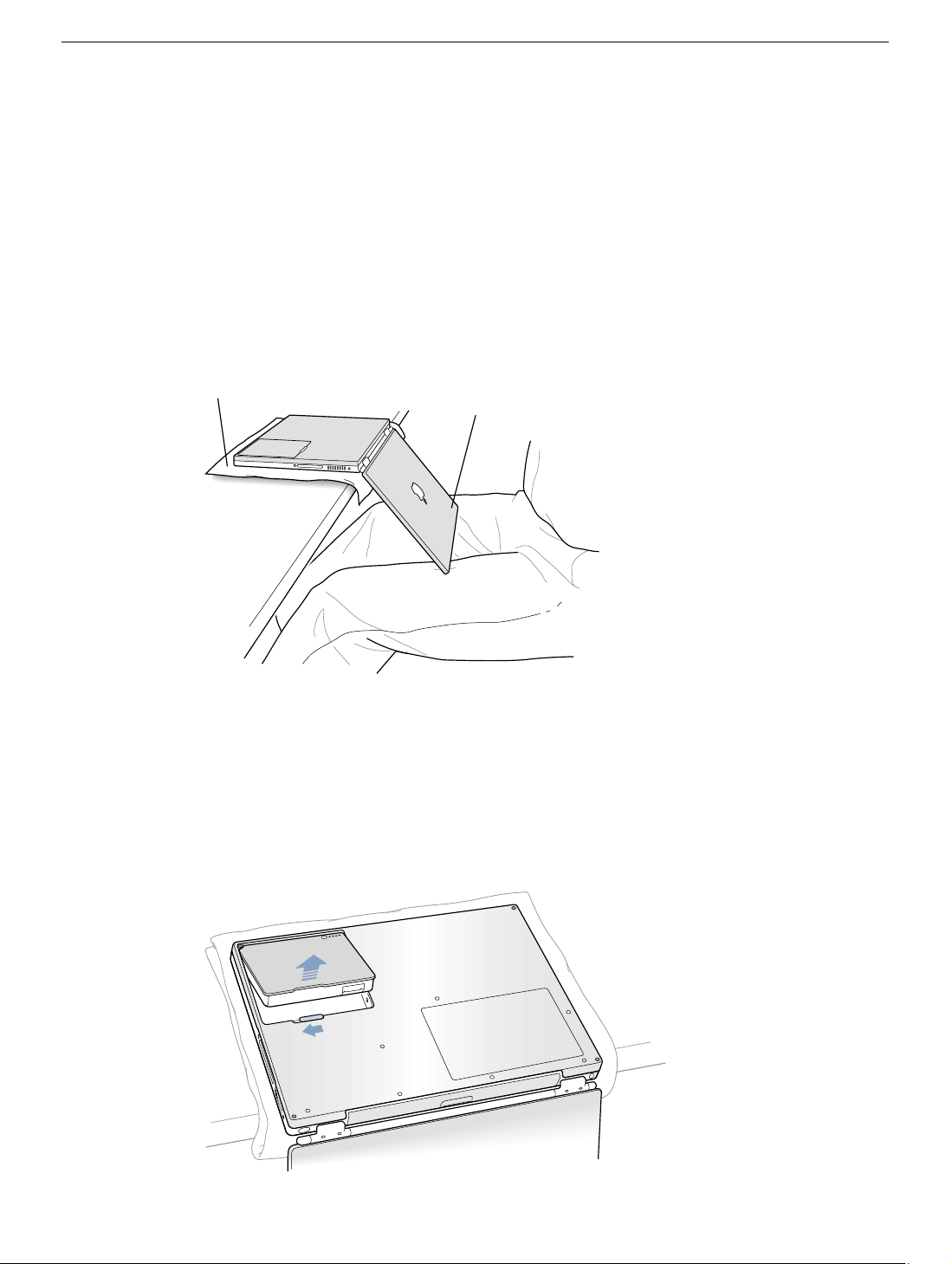
4. Place a towel or soft cloth on a table in front of you. (Figure 1A)
The towel or cloth will protect the keyboard and display area of the PowerBook when
you flip it over to remove the battery and bottom case. Make sure it covers an area
large enough for your PowerBook and that it hangs over the edge of the table.
5. With the display open at an angle greater than 90 degrees, carefully flip the
PowerBook over and lay it flat, fully on the table. Make sure the display hangs over the
edge of the table and rests lightly on your lap. (Figure 1B)
Important: Do not open the display farther than the angle shown.
Figure 1
A
B
6. Remove the battery by sliding the battery latch to the left. Make sure to return the latch
fully to the right. (Figure 2)
Removing the battery will prevent you from accidentally turning on the computer.
Warning: Removing the battery before shutting down your computer may
result in data loss.
Figure 2
PowerBook G4 (DVI) Bottom Case - 2
Page 25
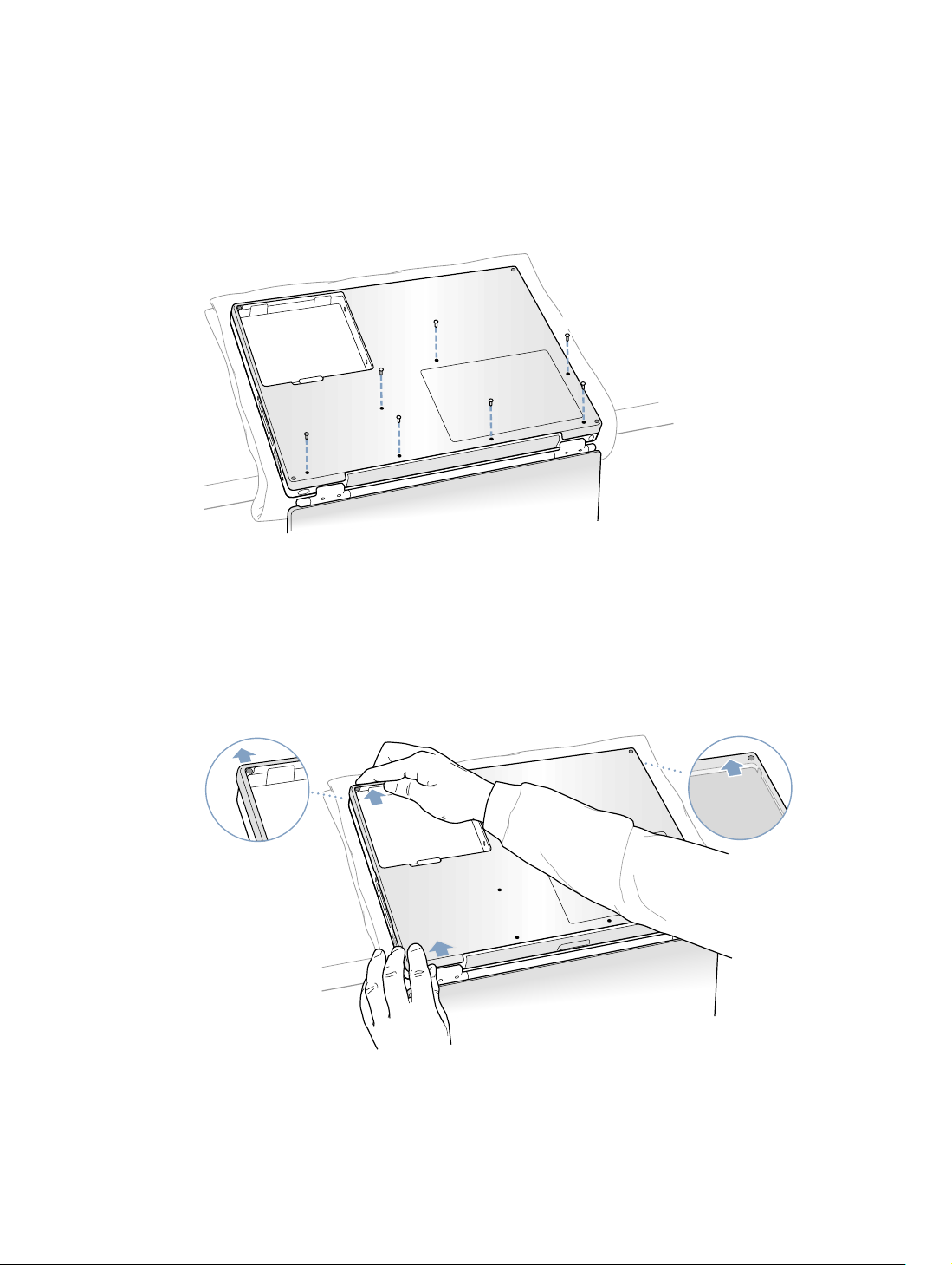
7. Using the appropriate screwdriver, remove the eight bottom case screws in the order
shown in the illustration. (Figure 3)
Important: To avoid damaging the case, be careful that the screwdriver tip does not
slip out of the screw head during removal.
Figure 3
1
2
7
6
5
3
4
Note: The following three steps explain how to remove the bottom case by disengaging it
at the left and right sides and then carefully pivoting it forward.
Important: During this procedure, do not push on the rubber feet of the bottom case.
8. Carefully slide the bottom case away from you. (Figure 4)
Figure 4
PowerBook G4 (DVI) Bottom Case - 3
Page 26
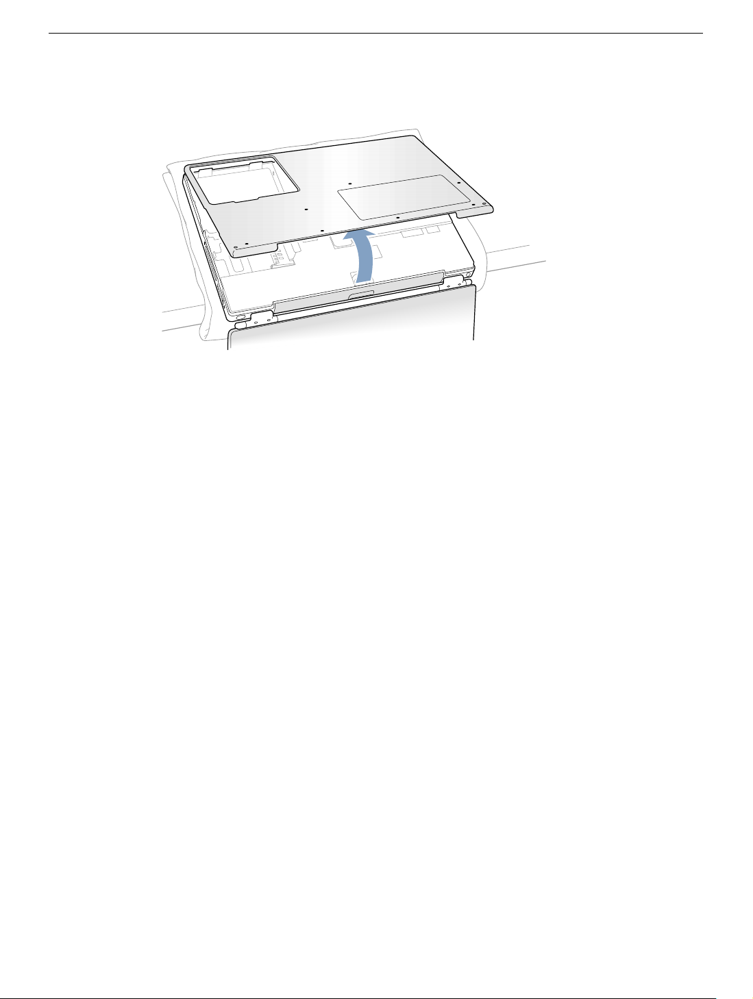
9. Pivot the bottom case up as shown in the illustration below. (Figure 5)
Figure 5
Installing the Replacement Bottom Case
1. To install the new bottom case, place it over the bottom of the computer in the same
orientation as the original bottom case.
2. Align the notches on the right and left sides of the case (some of these can be viewed
through the battery opening). Then press down and toward you slightly to secure the
case.
Important: Make sure that the seams between the bottom case and the frame are
closed. Verify that the case lies flat and fits properly around the battery latch and that
the alignment tab that protrudes on the underside of the bottom case, shown in the
illustration (Figure 6A), is seated properly.
Note: To help with alignment, apply pressure to the bottom case at the back of the
battery compartment opening, near the latch, and on the front and back outside
edges of the case.
3. Check that the eight screw holes on the case align with the holes on the computer.
PowerBook G4 (DVI) Bottom Case - 4
Page 27
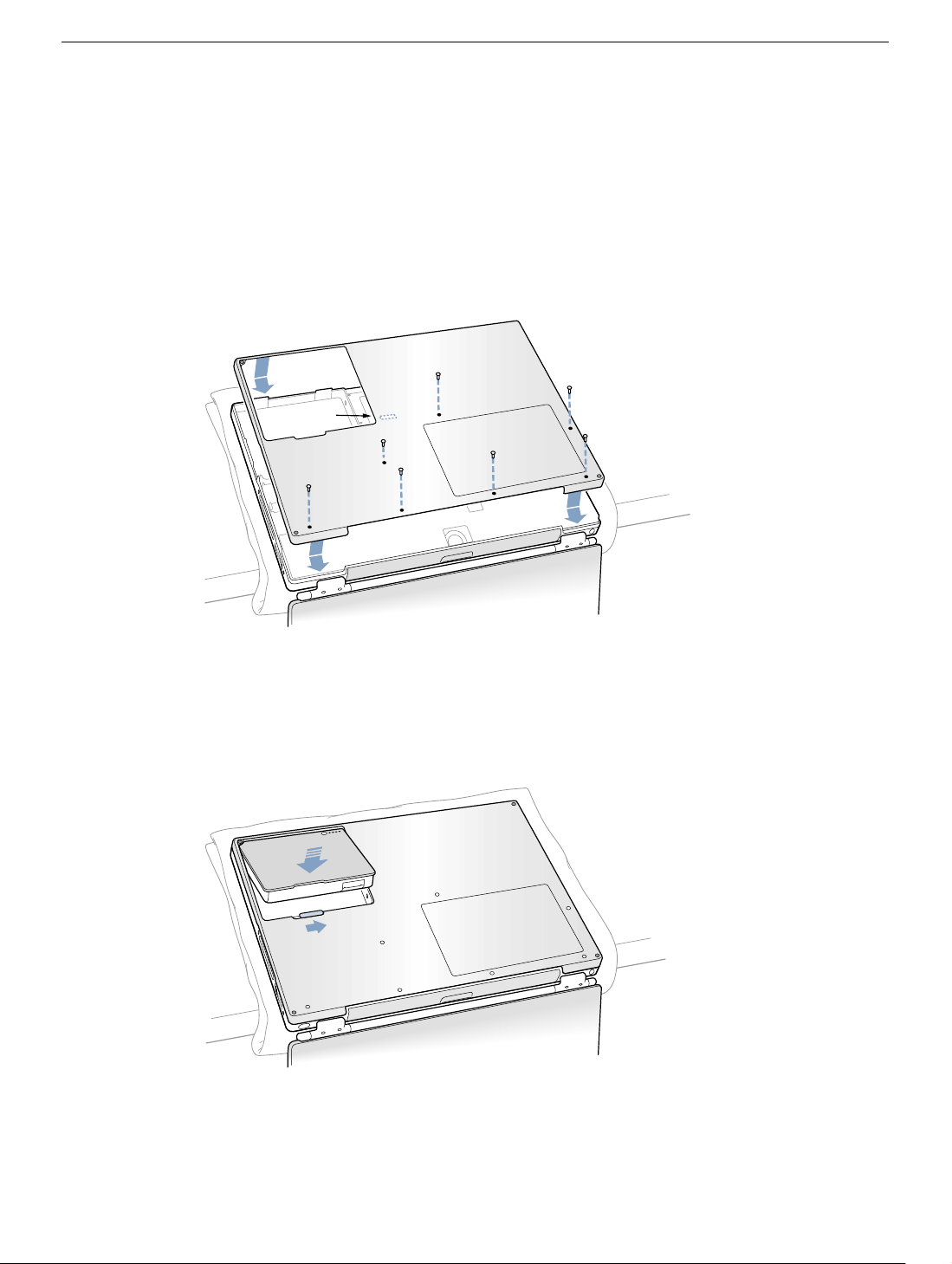
4. Replace the eight screws in the order shown in the illustration (Figure 6). Do not
overtighten the screws or damage could result.
Note: The screws must go in straight and easily; if they do not, readjust the bottom
case for proper alignment.
Important: To avoid damaging the case, be careful that the screwdriver tip does not
slip out of the screw head during tightening.
Figure 6
7
A
3
6
2
1
5
4
5. Replace the battery. (Figure 7)
Important: Make sure that the battery locks securely into place and that the battery
latch is slid all the way into the locked position.
Figure 7
PowerBook G4 (DVI) Bottom Case - 5
Page 28
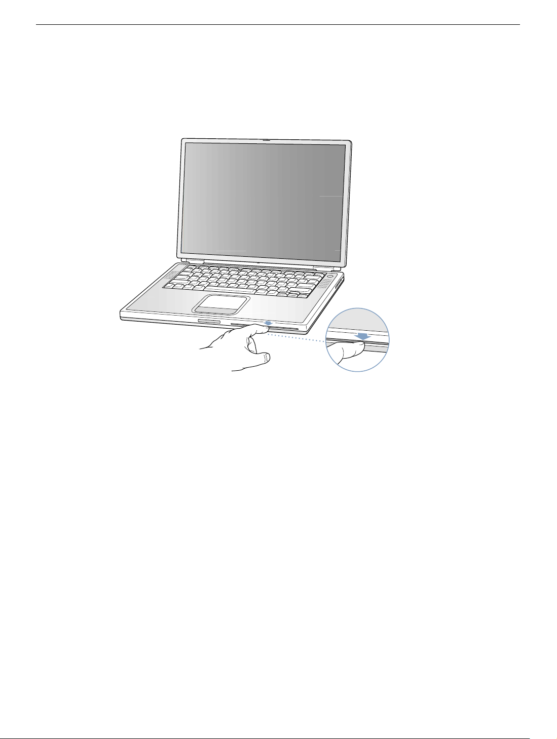
6. Turn the computer over so that the optical drive slot faces you. Verify that the bottom
case is flush with the front edge of the slot. If the case is slightly bowed and there is a
gap near the center of the slot, carefully pull the bottom edge of the slot until it clicks
into place and becomes flush with the bottom case. (Figure 8)
Figure 8
®
7. Reconnect the power cord and any other cables that were connected, and restart your
computer.
Warning: Never turn on your computer unless all of its internal and external
parts are in place and it is closed. Operating the computer when it is open or
missing parts can damage your computer or cause injury.
PowerBook G4 (DVI) Bottom Case - 6
Page 29

Apple Computer, Inc.
© 2002 Apple Computer, Inc. All rights reserved.
This document is protected under U.S. Copyright Law and International Treaties, and no
part of this document may be reproduced in any form without written permission from
Apple.
Apple is not responsible for typographical, printing, or inadvertent errors.
Apple Computer, Inc.
1 Infinite Loop
Cupertino, CA 95014-2084
USA
+ 1 408 996 1010
http://www.apple.com
Apple, the Apple logo, and PowerBook are trademarks of Apple Computer, Inc., registered
in the U.S. and other countries.
PowerBook G4 (DVI) Bottom Case - 7
Page 30

PowerBook G4 (DVI)
AirPort Card
Replacement Instructions
Follow the instructions in this sheet carefully. Failure to follow these instructions could
damage your equipment and void its warranty.
Note: Written and video instructions covering customer-installable parts are available at
http://www.info.apple.com/installparts/.
Warning: Sharp edges can exist inside your computer and on any parts being
removed or installed. Use caution to avoid injury. Keep small parts away from
children.
Tools Required
• Soft towel or cloth, larger than the PowerBook
• Torx T8 screwdriver
Opening the Computer
Warning: Always shut down your computer before opening it to avoid damaging its
internal components or causing injury. After you shut down the computer, the
internal components can be very hot. Let the computer cool down before
continuing.
To access the AirPort Card, you must first remove the battery and bottom case.
1. Place your computer on a clean, flat surface.
2. Shut down your computer and wait thirty minutes before continuing.
3. Disconnect the power cord and any other cables connected to the computer.
Page 31
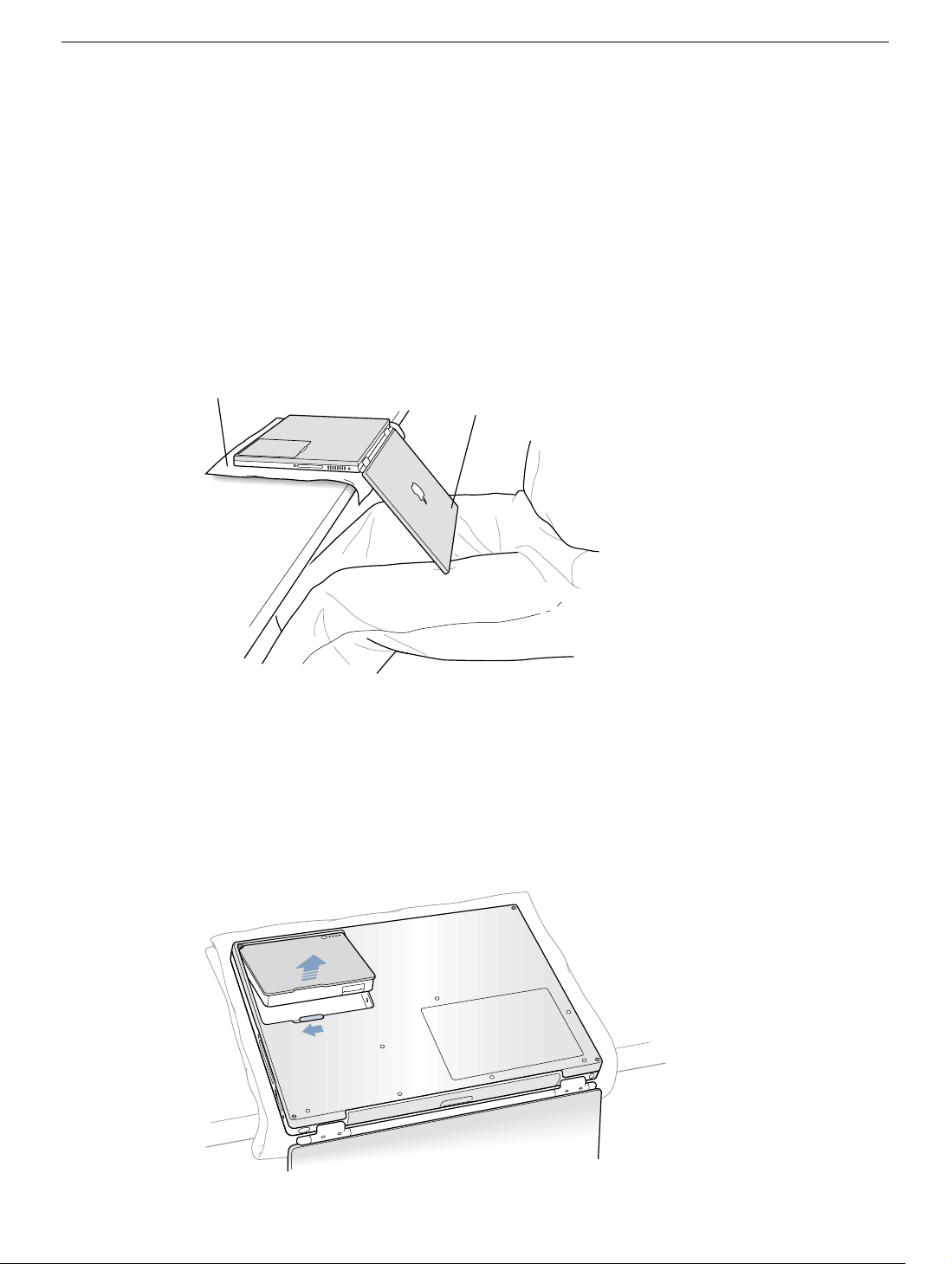
4. Place a towel or soft cloth on a table in front of you. (Figure 1A)
The towel or cloth will protect the keyboard and display area of the PowerBook when
you flip it over to remove the battery and bottom case. Make sure it covers an area
large enough for your PowerBook and that it hangs over the edge of the table.
5. With the display open at an angle greater than 90 degrees, carefully flip the
PowerBook over and lay it flat, fully on the table. Make sure the display hangs over the
edge of the table and rests lightly on your lap. (Figure 1B)
Important: Do not open the display farther than the angle shown.
Figure 1
A
B
6. Remove the battery by sliding the battery latch to the left. Make sure to return the latch
fully to the right. (Figure 2)
Removing the battery will prevent you from accidentally turning on the computer.
Warning: Removing the battery before shutting down your computer may
result in data loss.
Figure 2
PowerBook G4 (DVI) AirPort Card- 2
Page 32
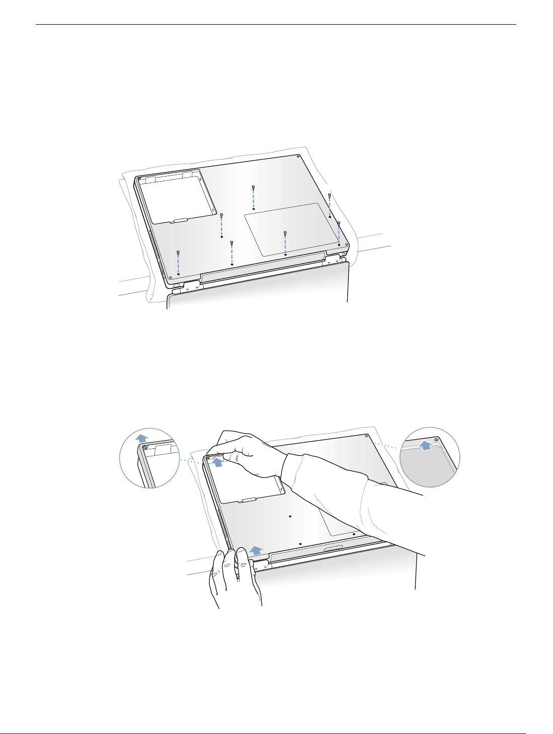
7. Using a Torx T8 screwdriver, remove the eight bottom case screws in the order shown
in the illustration. (Figure 3)
Important: To avoid damaging the case, be careful that the screwdriver tip does not
slip out of the screw head during removal.
Figure 3
1
2
7
6
5
3
4
Note: The following three steps explain how to remove the bottom case by disengaging it
at the left and right sides and then carefully pivoting it forward.
Important: During this procedure, do not push on the rubber feet of the bottom case.
8. Carefully slide the bottom case away from you. (Figure 4)
Figure 4
PowerBook G4 (DVI) AirPort Card- 3
Page 33
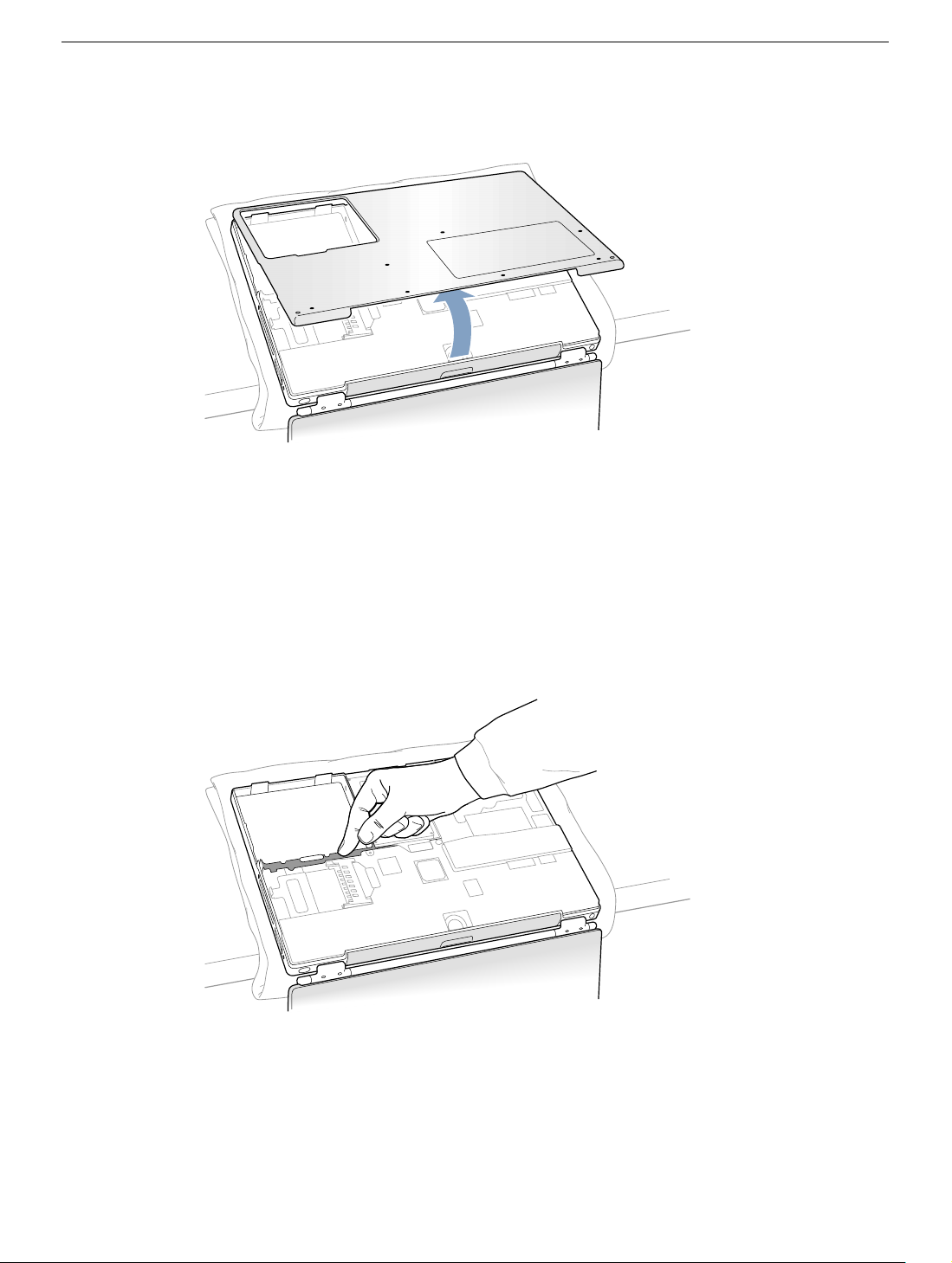
9. Pivot the bottom case up as shown in the illustration below. (Figure 5)
Figure 5
10. Touch the computer’s inside framework (a dull gray conductive composite material) to
discharge any static electricity, as shown. (Figure 6)
Important: To avoid electrostatic discharge damage, always ground yourself by
touching the computer’s framework before you touch any parts or install any
components inside the computer. To avoid static electricity building back up in your
body, do not walk around the room until you have completed your installation and
closed the computer.
Figure 6
PowerBook G4 (DVI) AirPort Card- 4
Page 34
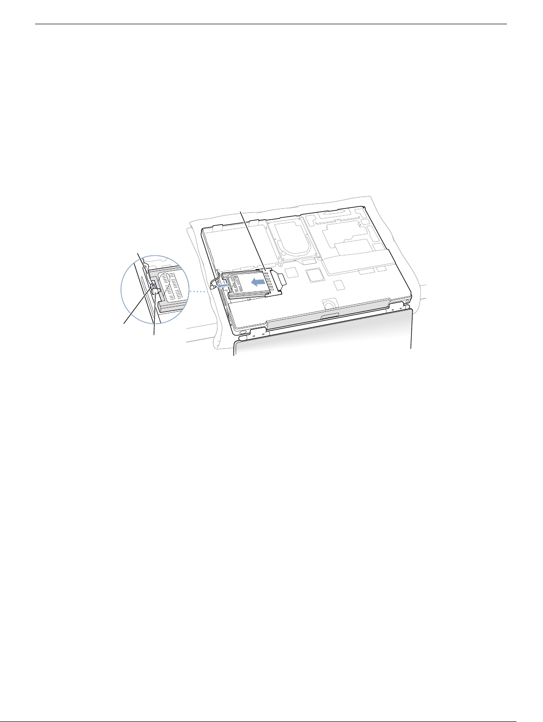
Removing the Installed AirPort Card
1. Pull back on the antenna clip (Figure 7A) to release the antenna cable connector
(Figure 7B) and allow the card to rise up slightly.
2. Pull the card from the AirPort connector (Figure 7D).
3. Hold the AirPort Card with one hand and grasp the antenna cable connector with the
other. While being careful not to strain the antenna cable (Figure 7C), firmly pull the
connector straight out of the AirPort Card.
Figure 7
D
C
A
B
Important: If the AirPort Card is not being replaced right away, replace the antenna
cable connector into its holder (Figure 9B) and pull the loop of the antenna cable up
slightly and away from the edge of the computer case. This prevents the cable from
interfering with the PC card slot, below, or getting pinched during reassembly.
Also, if the insertion end of the AirPort Card connector is rotated up, push it down into
the level position. This allows the bottom case to install properly.
PowerBook G4 (DVI) AirPort Card- 5
Page 35
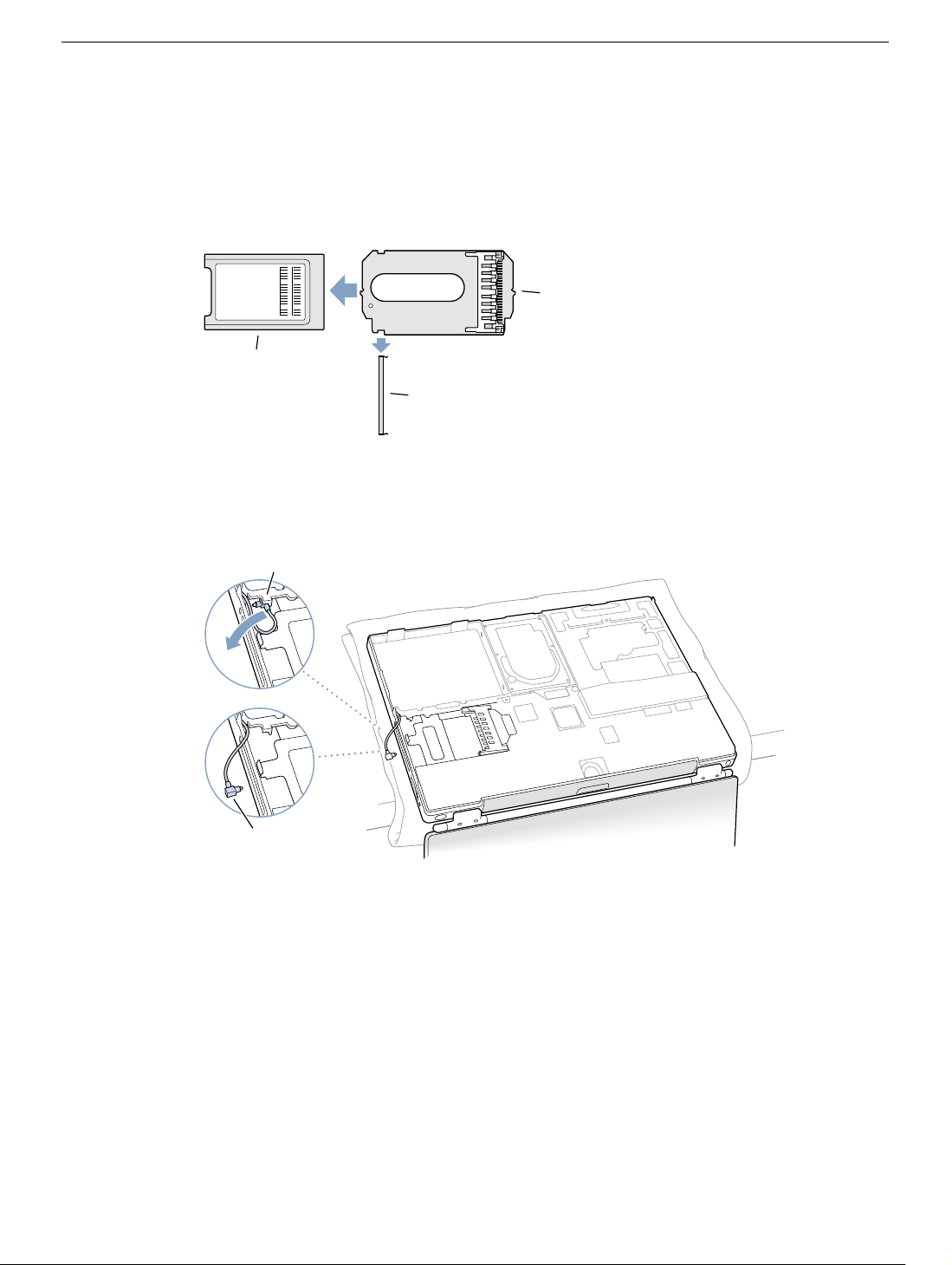
Installing the Replacement AirPort Card
1. If the AirPort Card to be installed came with the AirPort adapter (Figure 8A), remove
the metal clip (Figure 8B) and pull the AirPort Card (Figure 8C) from the adapter.
(The adapter and metal clip are not used with your PowerBook.)
Figure 8
A
C
B
2. If necessary, pull the AirPort antenna cable connector (Figure 9A) from its holder
(Figure 9B).
Figure 9
B
A
PowerBook G4 (DVI) AirPort Card- 6
Page 36
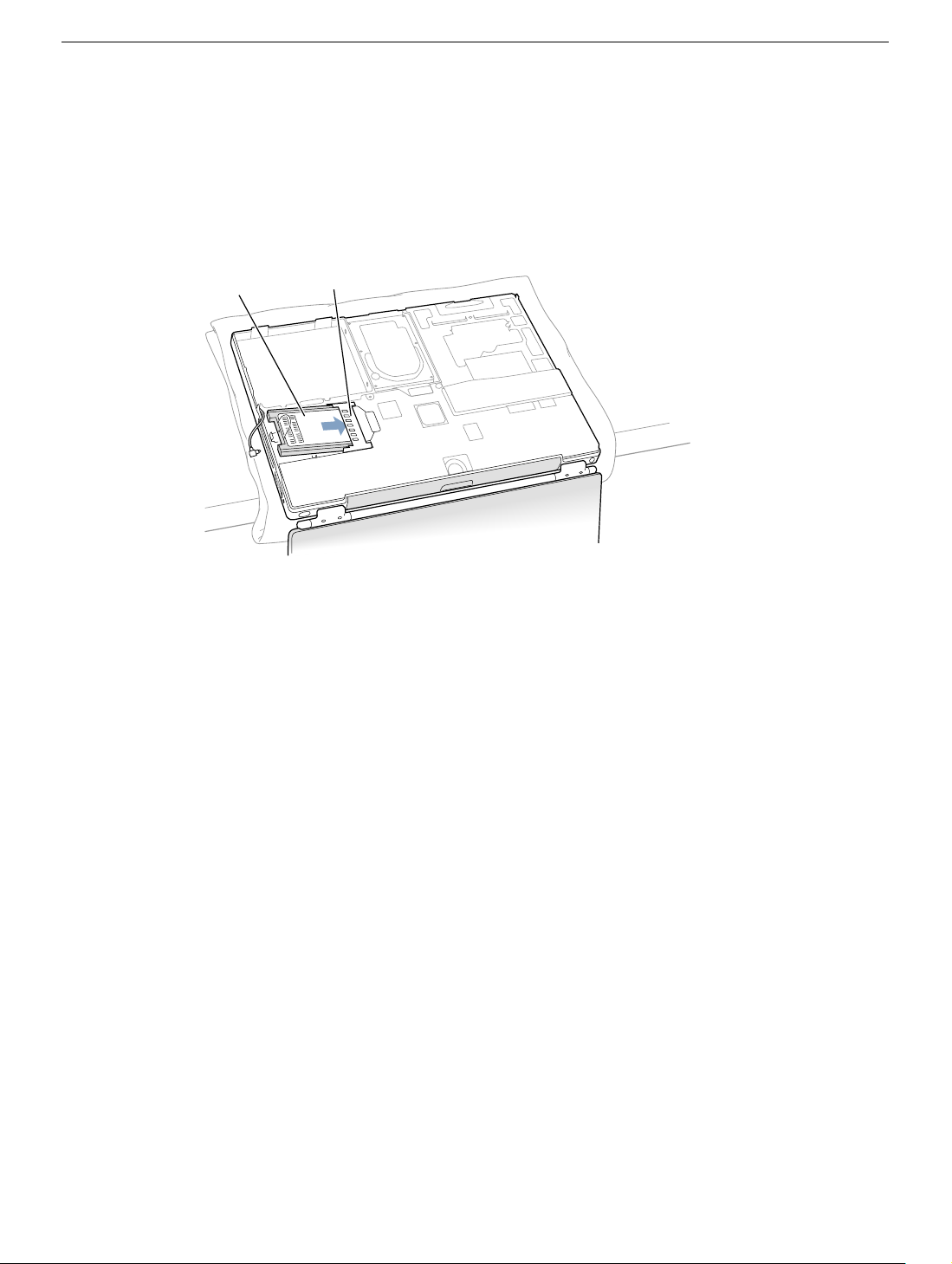
3. Pull up the insertion end of the AirPort Card connector (Figure 10A) to raise it up
slightly, if it is not already up.
4. Position the AirPort Card (Figure 10B) with the AirPort ID numbers and bar code
facing up and slide the card into the connector. Make sure to slide the card all the way
in until the card is securely attached to the connector.
Figure 10
B
A
PowerBook G4 (DVI) AirPort Card- 7
Page 37
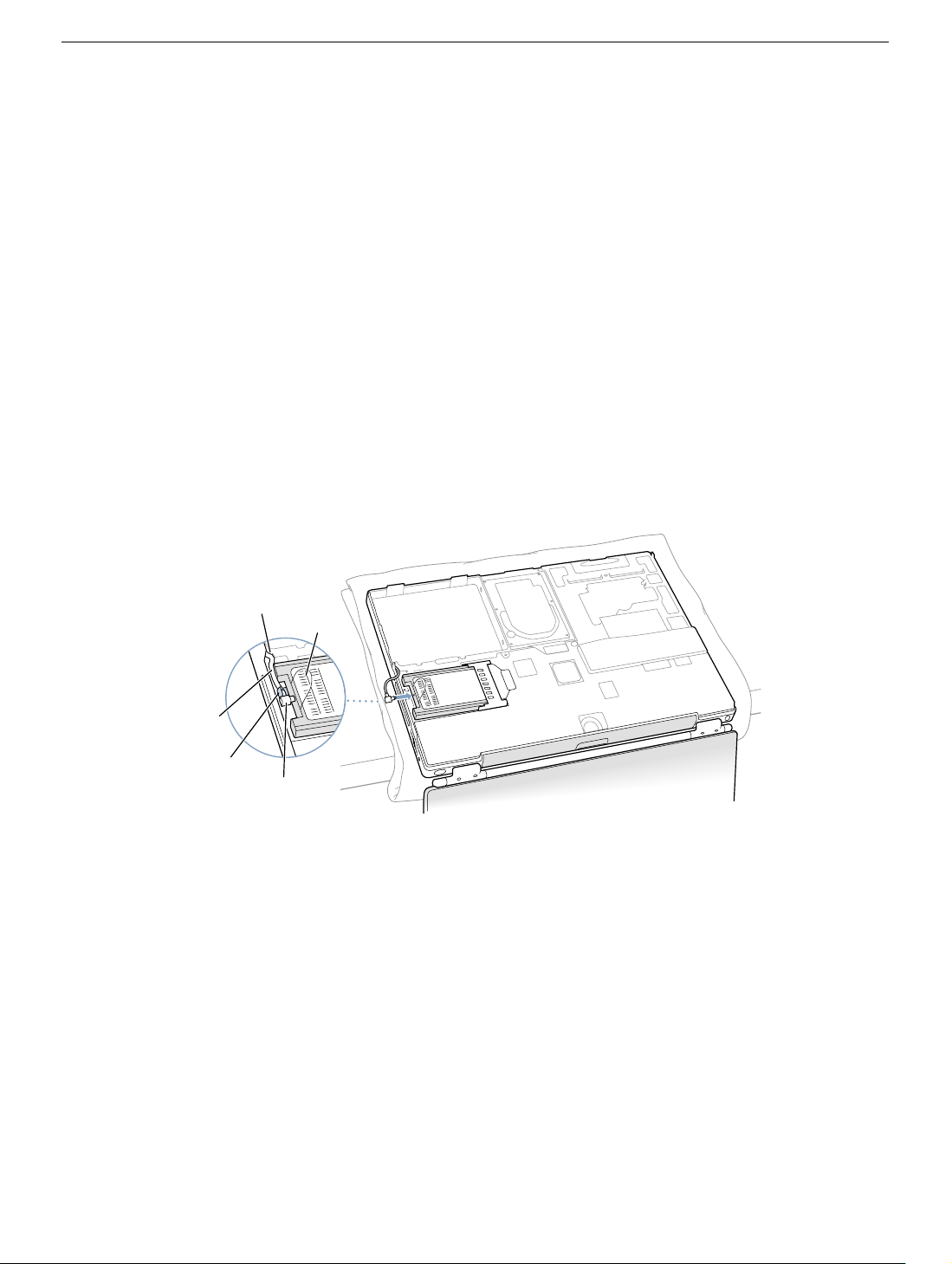
5. Plug the antenna cable connector (Figure 11A) into the port, which is located just
below the plastic tab (Figure 11B), on the end of the AirPort Card. Make sure the
connector is straight before inserting it into the card.
6. Push the AirPort Card down into its space until the antenna cable connector is
secured by the small antenna clip (Figure 11C).
Important: Route the antenna cable (Figure 11D) between the edge of the computer
and the AirPort Card. Verify that the cable is away from the edge of the computer so
that it will not be pinched during reassembly and that it does not sag down into the
PC card slot area (below the AirPort Card). Take up any extra cable by tucking it in
where shown (Figure 11E).
7. Fold the plastic tab (Figure 11B) on the AirPort Card over the top of the card.
Note: The plastic tab must be folded over the card during the installation of the
bottom case; otherwise you will not be able to securely attach the bottom case to the
computer.
Figure 11
E
B
D
C
A
PowerBook G4 (DVI) AirPort Card- 8
Page 38
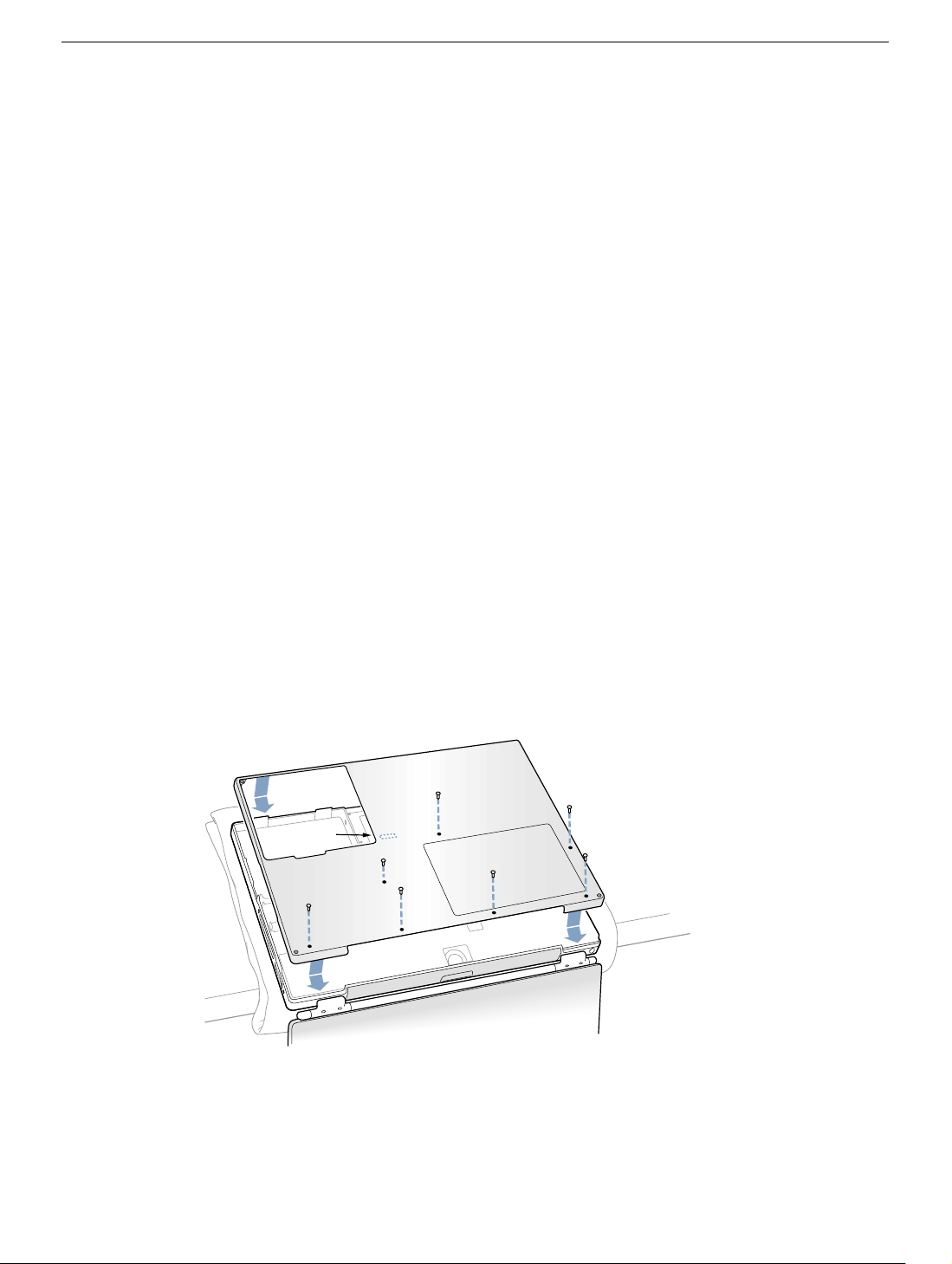
Closing the Computer
1. To replace the bottom case, place it over the bottom of the computer in the same
orientation as the original bottom case.
2. Align the notches on the right and left sides of the case (some of these can be viewed
through the battery opening). Then press down and toward you slightly to secure the
case.
Important: Make sure that the seams between the bottom case and the frame are
closed. Verify that the case lies flat and fits properly around the battery latch and that
the alignment tab that protrudes on the underside of the bottom case, shown in the
illustration (Figure 12A), is seated properly.
Note: To help with alignment, apply pressure to the bottom case at the back of the
battery compartment opening, near the latch, and on the front and back outside
edges of the case.
3. Check that the eight screw holes on the case align with the holes on the computer.
4. Replace the eight screws in the order shown in the illustration (Figure 12). Do not
overtighten the screws or damage could result.
Note: The screws must go in straight and easily; if they do not, readjust the bottom
case for proper alignment.
Important: To avoid damaging the case, be careful that the screwdriver tip does not
slip out of the screw head during tightening.
Figure 12
7
A
3
6
2
1
5
4
PowerBook G4 (DVI) AirPort Card- 9
Page 39
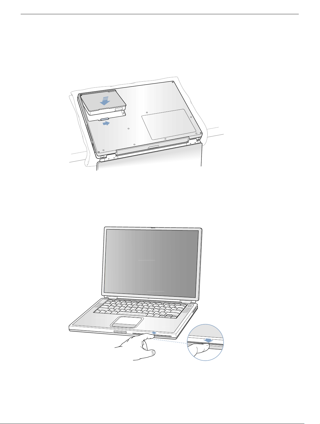
5. Replace the battery. (Figure 13)
Important: Make sure that the battery locks securely into place and that the battery
latch is slid all the way into the locked position.
Figure 13
6. Turn the computer over so that the optical drive slot faces you. Verify that the bottom
case is flush with the front edge of the slot. If the case is slightly bowed and there is a
gap near the center of the slot, carefully pull the bottom edge of the slot until it clicks
into place and becomes flush with the bottom case. (Figure 14)
Figure 14
®
PowerBook G4 (DVI) AirPort Card- 10
Page 40

7. Reconnect the power cord and any other cables that were connected, and restart your
computer.
Warning: Never turn on your computer unless all of its internal and external
parts are in place and it is closed. Operating the computer when it is open or
missing parts can damage your computer or cause injury.
Apple Computer, Inc.
© 2002 Apple Computer, Inc. All rights reserved.
This document is protected under U.S. Copyright Law and International Treaties, and no
part of this document may be reproduced in any form without written permission from
Apple.
Apple is not responsible for typographical, printing, or inadvertent errors.
Apple Computer, Inc.
1 Infinite Loop
Cupertino, CA 95014-2084
USA
+ 1 408 996 1010
http://www.apple.com
Apple, the Apple logo, and PowerBook are trademarks of Apple Computer, Inc., registered
in the U.S. and other countries.
PowerBook G4 (DVI) AirPort Card- 11
Page 41

PowerBook G4 (DVI)
Hard Drive
Replacement Instructions
Follow the instructions in this sheet carefully. Failure to follow these instructions could
damage your equipment and void its warranty.
Note: Written and video instructions covering customer-installable parts are available at
http://www.info.apple.com/installparts/.
Warning: Sharp edges can exist inside your computer and on any parts being
removed or installed. Use caution to avoid injury. Keep small parts away from
children.
Tools Required
• Soft towel or cloth, larger than the PowerBook
• Torx T8 screwdriver (provided with hard drive)
Backing Up Your Data
Warning: Before replacing your hard drive, make sure you back up all data on the
drive.
Opening the Computer
Warning: Always shut down your computer before opening it to avoid damaging its
internal components or causing injury. After you shut down the computer, the
internal components can be very hot. Let the computer cool down before
continuing.
To access the hard drive, you must first remove the battery and bottom case.
1. Place your computer on a clean, flat surface.
2. Shut down your computer and wait thirty minutes before continuing.
3. Disconnect the power cord and any other cables connected to the computer.
Page 42
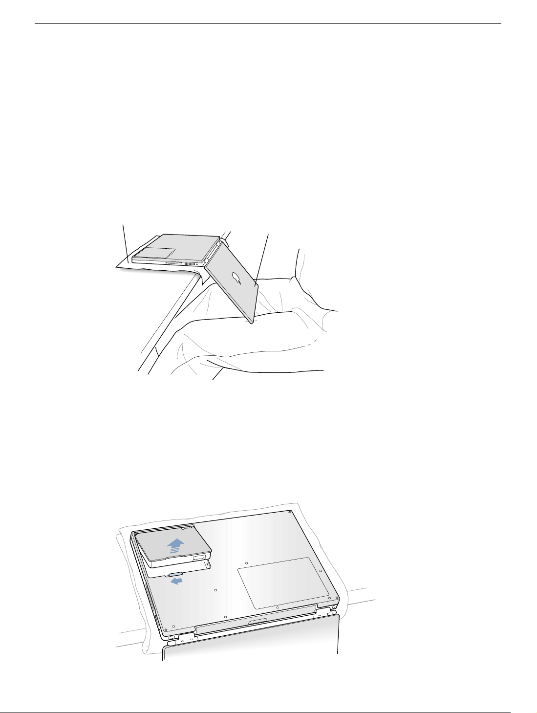
4. Place a towel or soft cloth on a table in front of you. (Figure 1A)
The towel or cloth will protect the keyboard and display area of the PowerBook when
you flip it over to remove the battery and bottom case. Make sure it covers an area
large enough for your PowerBook and that it hangs over the edge of the table.
5. With the display open at an angle greater than 90 degrees, carefully flip the
PowerBook over and lay it flat, fully on the table. Make sure the display hangs over the
edge of the table and rests lightly on your lap. (Figure 1B)
Important: Do not open the display farther than the angle shown.
Figure 1
A
B
6. Remove the battery by sliding the battery latch to the left. Make sure to return the latch
fully to the right. (Figure 2)
Removing the battery will prevent you from accidentally turning on the computer.
Warning: Removing the battery before shutting down your computer may
result in data loss.
Figure 2
PowerBook G4 (DVI) Hard Drive - 2
Page 43
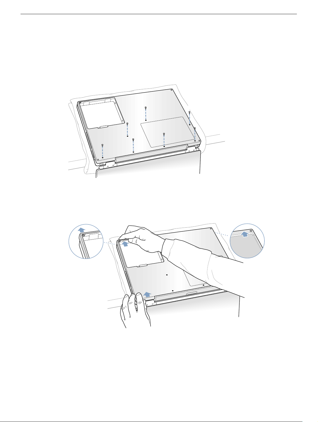
7. Using a Torx T8 screwdriver, remove the eight bottom case screws in the order shown
in the illustration. (Figure 3)
Important: To avoid damaging the case, be careful that the screwdriver tip does not
slip out of the screw head during removal.
Figure 3
1
2
7
6
5
3
4
Important: During this procedure, do not push on the rubber feet of the bottom case.
8. Carefully slide the bottom case away from you. (Figure 4)
Figure 4
PowerBook G4 (DVI) Hard Drive - 3
Page 44
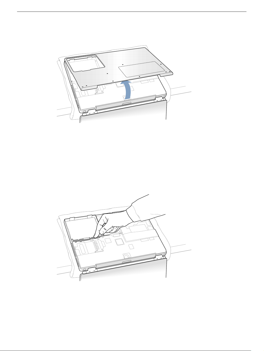
9. Pivot the bottom case up as shown in the illustration below. (Figure 5)
Figure 5
10. Touch the computer’s inside framework (a dull gray conductive composite material) to
discharge any static electricity, as shown. (Figure 6)
Important: To avoid electrostatic discharge damage, always ground yourself by
touching the computer’s framework before you touch any parts or install any
components inside the computer. To avoid static electricity building back up in your
body, do not walk around the room until you have completed your installation and
closed the computer.
Figure 6
PowerBook G4 (DVI) Hard Drive - 4
Page 45
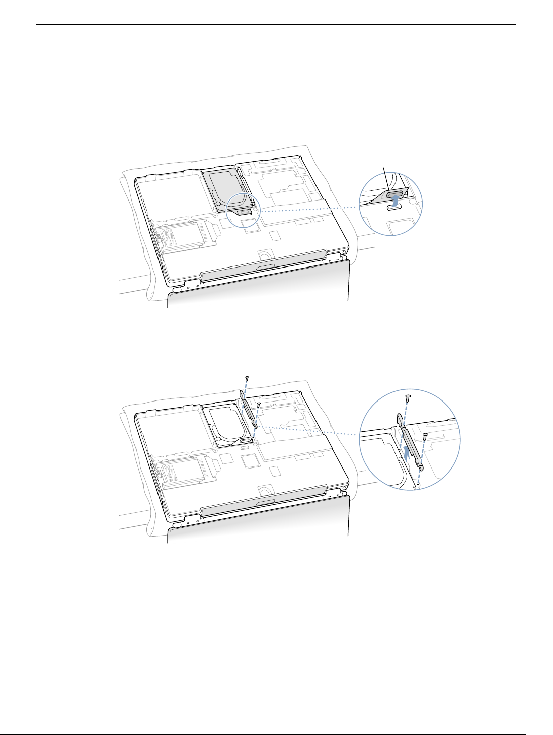
Removing the Installed Hard Drive
1. With your fingers, carefully pry up the hard drive cable connector (Figure 7A) at its
sides to disconnect it from the logic board. You may need to pry one side, then the
other, in a rocking motion.
Figure 7
A
2. With a Torx T8 screwdriver, remove the two screws that secure the hard drive
mounting bracket, and remove the bracket. (Figure 8)
Figure 8
PowerBook G4 (DVI) Hard Drive - 5
Page 46
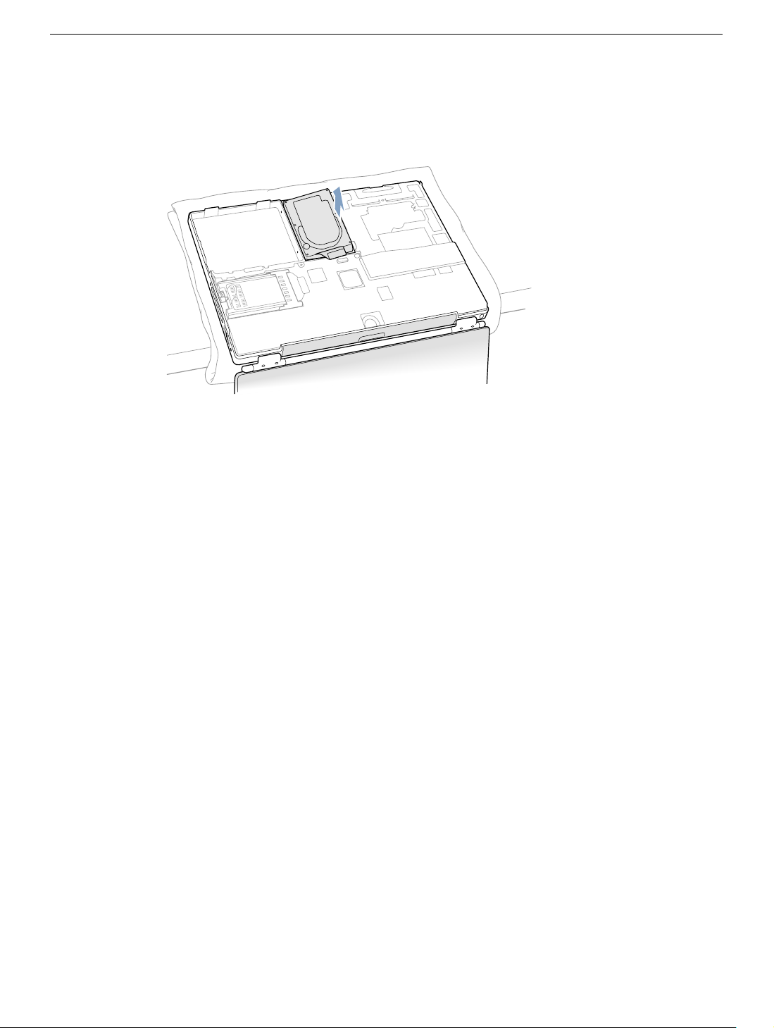
3. Pull up on the right side of the hard drive to remove. (Figure 9)
Important: Do not pull on the connector cable or use the cable as a handle.
Figure 9
Note: There are four rubber stoppers on the hard drive that fit over screws (two on
each side). Remove any that may have fallen off or that remain in the holes in the
mounting bracket inside the computer.
4. Carefully remove the Mylar sheath and cable from the hard drive to transfer to the
replacement drive.
Important: The connector pins on the hard drive are fragile and bend easily. Use
care to keep the pins straight when removing or installing.
PowerBook G4 (DVI) Hard Drive - 6
Page 47
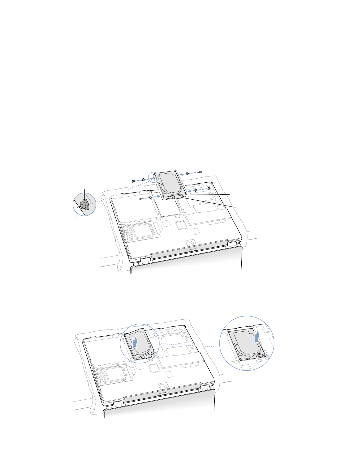
Installing the Replacement Hard Drive
Warning: To avoid potential injury, avoid touching or brushing against the thin strip
of metal that extends up from the hard drive mounting bracket (Figure 10A).
Important: Avoid touching the optical drive as you perform this procedure.
1. Make sure that the screws (Figure 10A) and rubber stoppers (Figure 10B) are in
place on the sides of the replacement drive.
2. Install the Mylar sheath (Figure 10C) so that it covers the bottom and left and right
sides of the drive. The sheath is directional—install it so that it does not extend beyond
the front of the hard drive.
3. Carefully install the hard drive cable (Figure 10D). The cable connector is keyed to fit
only one way.
Figure 10
B
C
D
A
4. Insert the left side of the drive first, then the right. Use a screwdriver through the frame
holes on the left side to help align the stoppers, if necessary. (Figure 11)
Figure 11
PowerBook G4 (DVI) Hard Drive - 7
Page 48
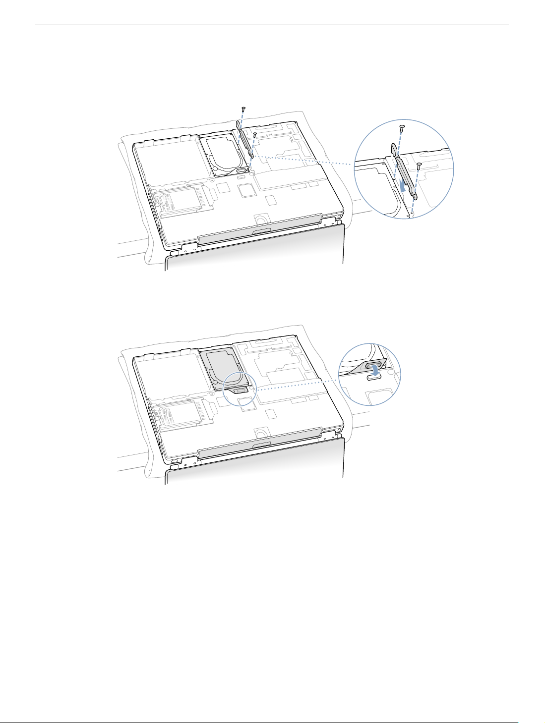
5. With a Torx T8 screwdriver, replace the two screws that secure the hard disk to the
mounting bracket. (Figure 12)
Figure 12
6. Connect the hard drive cable connector (Figure 13) to the logic board.
Figure 13
PowerBook G4 (DVI) Hard Drive - 8
Page 49
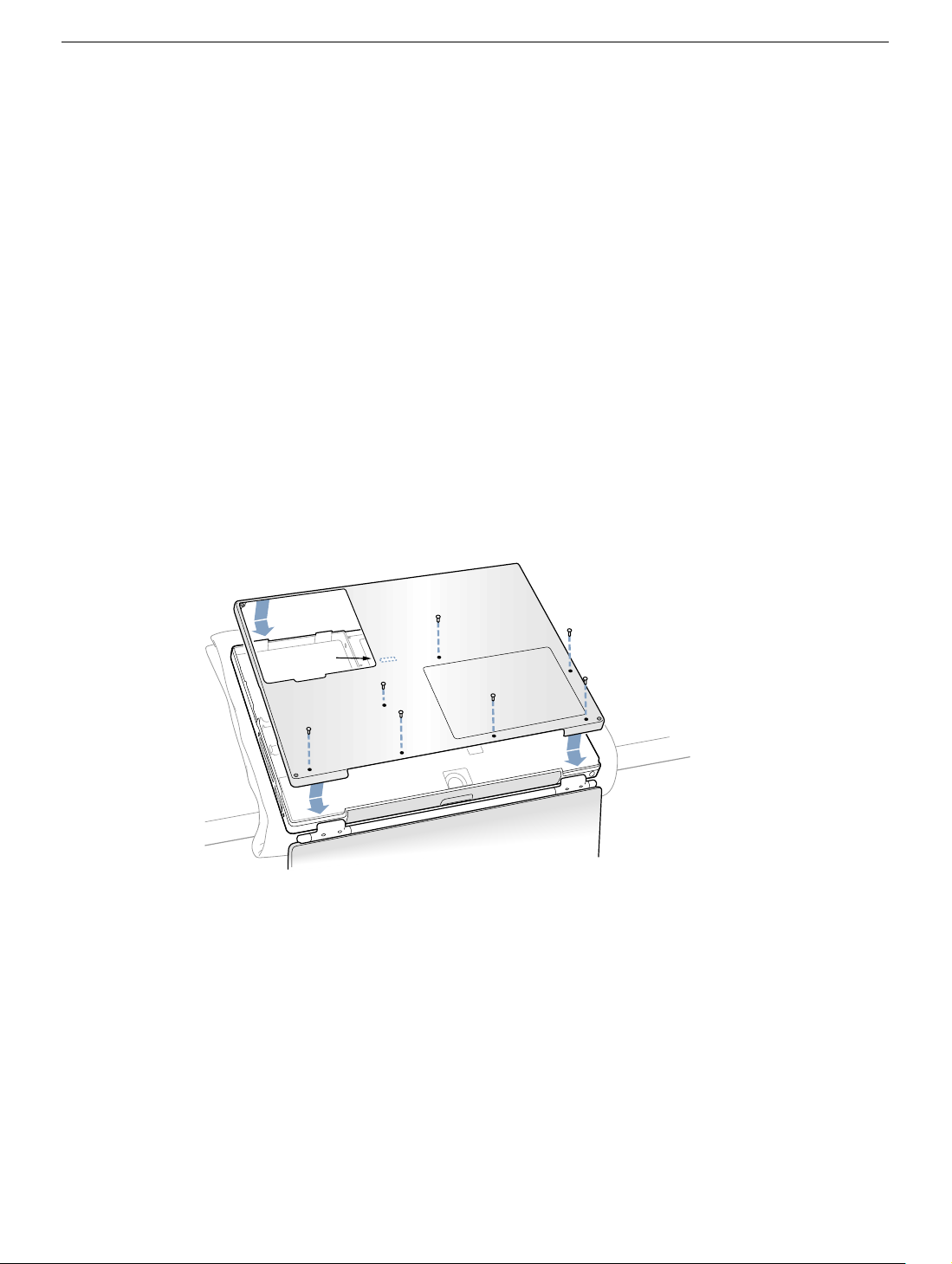
Closing the Computer
1. Attach the bottom case to the computer and replace the seven screws in the order
shown in the illustration below (Figure 14).
Line up the notches on the right and left sides of the case, then press down slightly to
secure the case. Check the alignment of the seven screw holes to make sure the
bottom case is properly positioned.
Important: Make sure that the seams between the bottom case and the frame are
closed. Check the outside edges and around the battery bay. Verify that the
alignment tab on the underside of the bottom case, shown in the illustration below
(Figure 14A), has seated, and the case lies flat.
Note: The screws must go in straight and easily; if they do not, readjust the bottom
case for proper alignment. Do not overtighten the screws or damage could result.
Important: To avoid damaging the case, be careful that the screwdriver tip does not
slip out of the screw head during tightening.
Figure 14
7
A
3
6
2
1
5
4
PowerBook G4 (DVI) Hard Drive - 9
Page 50
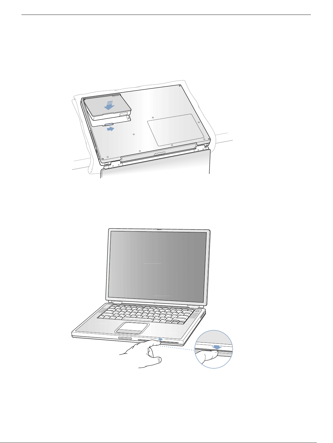
2. Replace the battery. (Figure 15)
Important: Make sure that the battery locks securely into place and that the battery
latch is slid all the way into the locked position.
Figure 15
3. Turn the computer over. Look at the optical drive slot to make sure that the case is
properly secured. If a gap exists below the slot, gently pull the bottom of the optical
drive slot toward you until it clicks into place and the gap is removed. (Figure 16)
Figure 16
®
PowerBook G4 (DVI) Hard Drive - 10
Page 51

4. Reconnect the power cord and any other cables that were connected, and restart your
computer.
Warning: Never turn on your computer unless all of its internal and external
parts are in place and it is closed. Operating the computer when it is open or
missing parts can damage your computer or cause injury.
5. Restore the data from your backup to the new drive.
6. Check the operation of the optical drive. If the hard drive is installed incorrectly, the
optical drive mechanism might not spin correctly and will result in mechanical noise
when playing a disc.
Apple Computer, Inc.
© 2002 Apple Computer, Inc. All rights reserved.
This document is protected under U.S. Copyright Law and International Treaties, and no
part of this document may be reproduced in any form without written permission from
Apple.
Apple is not responsible for typographical, printing, or inadvertent errors.
Apple Computer, Inc.
1 Infinite Loop
Cupertino, CA 95014-2084
USA
+ 1 408 996 1010
http://www.apple.com
Apple, the Apple logo, and PowerBook are trademarks of Apple Computer, Inc., registered
in the U.S. and other countries.
PowerBook G4 (DVI) Hard Drive - 11
Page 52

PowerBook G4 (DVI)
Modem Filter Board
Replacement Instructions
The following instructions explain how to replace the modem EMI filter board in the
PowerBook G4 (DVI) computer.
Tools
• Black stick (nylon probe tool 922-5065) or other ESD-safe, non-marring tool
• Torx T8 screwdriver
Preliminary Steps
Before you begin, remove the following:
• Battery
• Keyboard
© 2002 Apple Computer, Inc. All rights reserved. Updated: 2002-04-29
Page 53
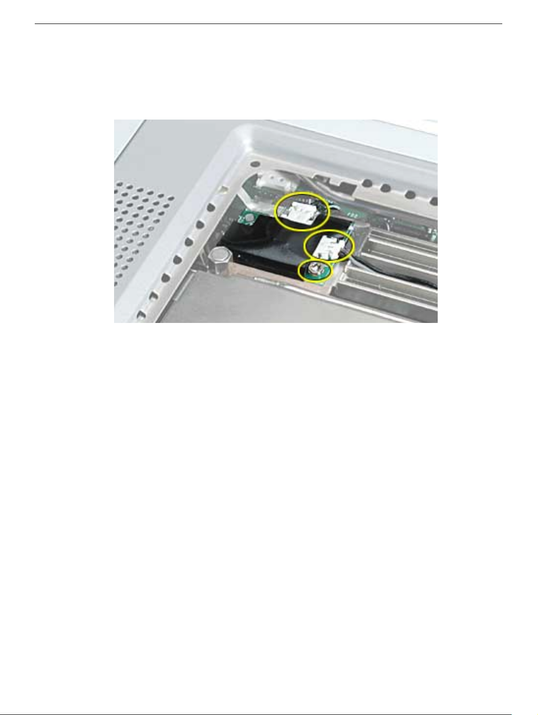
Procedure
1. Disconnect the RJ-11 and the modem wire connectors from the modem filter board.
2. Remove the Torx T8 screw.
3. Guide the modem filter board out of the case.
PowerBook G4 (DVI) Modem Filter Board - 2
Page 54

PowerBook G4 (DVI)
DC-In Board
Replacement Instructions
The following instructions explain how to replace the DC-in board in the PowerBook G4
(DVI) computer.
Important: Check the “Heat Exchanger Upgrade” and the “Check for PowerBook G4 (DVI)
867 MHz Upgrade” chapters of this manual for possible configuration changes.
Tools
• Black stick (nylon probe tool 922-5065) or other ESD-safe, non-marring tool
• Torx T6 screwdriver
Preliminary Steps
Before you begin, remove the following:
• Battery
• Bottom case
© 2003 Apple Computer, Inc. All rights reserved. Updated: 14 October 2003
Page 55
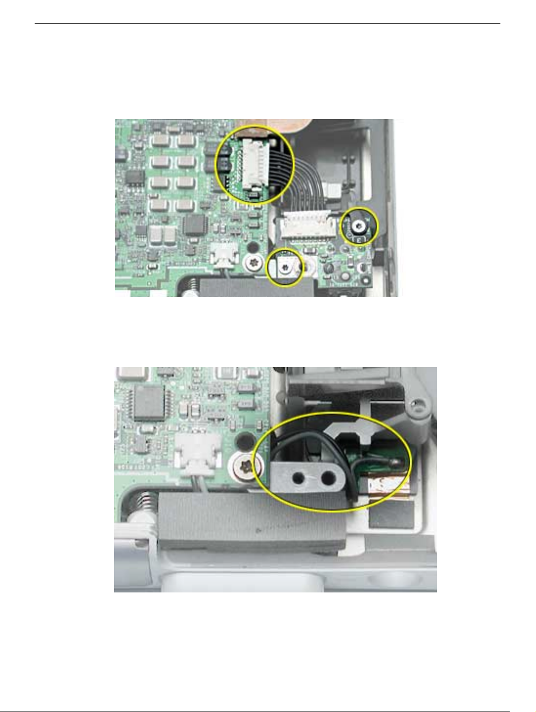
Procedure
1. Disconnect the DC-in board cable connector from the logic board.
2. Remove the two Torx T6 screws.
3. Guide the DC-in board out of the case.
Replacement Note: If you performed a procedure that also removed the logic board,
ensure that the power button cable routes as shown.
PowerBook G4 (DVI) DC-In Board - 2
Page 56
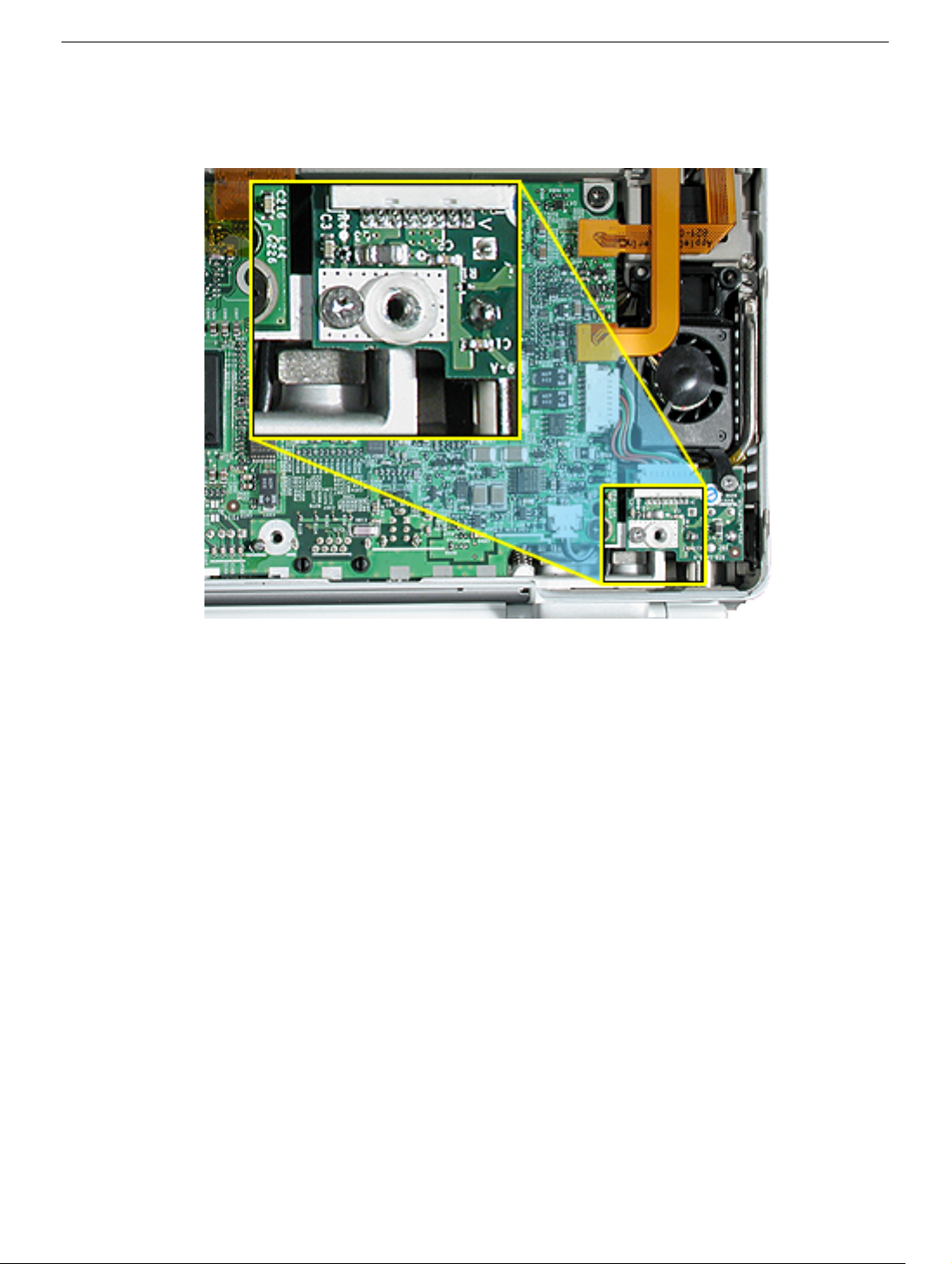
Replacement Notes:
• Install or transfer the 1 mm plastic spacer washer to the replacement DC-In board.
• When replacing the DC-in board, ensure that the secondary fan or bracket is seated
properly over the pin on the rib frame, and with its securing-tab resting on top of the
DC-In board. If one screw was longer, replace it through the fan’s securing-tab.
• Make sure that the DC connector is straight and centered in the port opening. With the
power adapter unplugged, the adapter connector may be inserted onto the DC
connector to ensure that the connector is centered and straight before securing the
DC-in board.
PowerBook G4 (DVI) DC-In Board - 3
Page 57
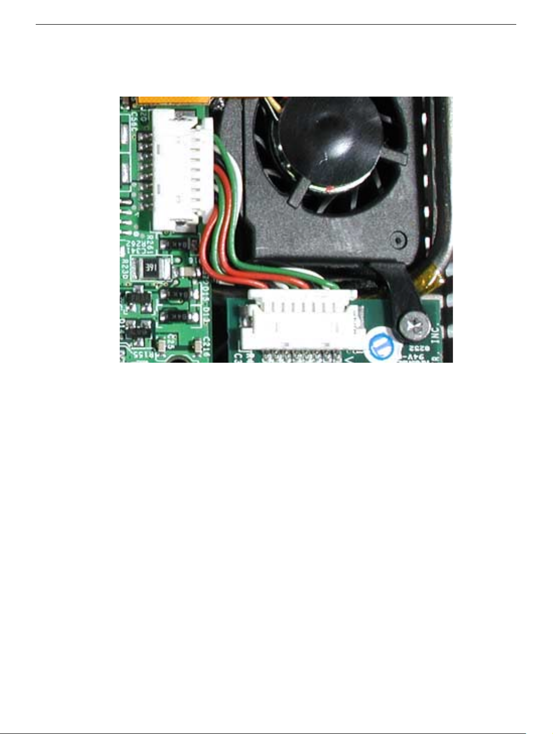
• If a secondary fan is installed, bend the DC-In board cable wires around the edge of
the fan, as shown, so they do not interfere with the fan or air flow.
PowerBook G4 (DVI) DC-In Board - 4
Page 58

PowerBook G4 (DVI)
Inverter Board
Replacement Instructions
The following instructions explain how to replace the inverter board in the PowerBook G4
(DVI) computer.
Tools
• Black stick (nylon probe tool 922-5065) or other ESD-safe, non-marring tool
• Torx T6 screwdriver
Preliminary Steps
Before you begin, remove the following:
• Battery
• Bottom case
© 2002 Apple Computer, Inc. All rights reserved. Updated: 2002-04-29
Page 59
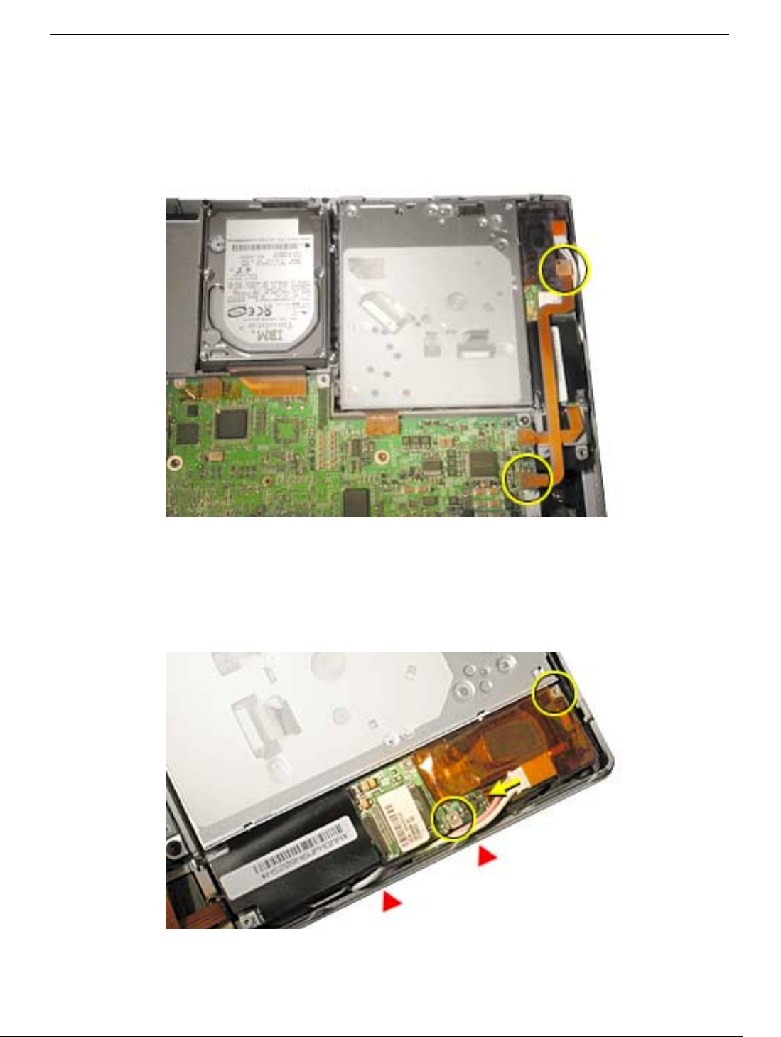
Procedure
Important: With the bottom case removed, be careful if turning over the computer. Some
components could become loose and fall out.
1. Disconnect the inverter board flex cable from both the inverter board and logic board.
2. Disconnect the bulb wire cable from the inverter board.
3. Remove the two T6 screws that secure the inverter board and remove the board.
Replacement Note: When reinstalling the replacement optical drive, ensure that the bulb
wire cable is safely within the case edge so that it will not get pinched by the bottom case.
PowerBook G4 (DVI) Inverter Board - 2
Page 60
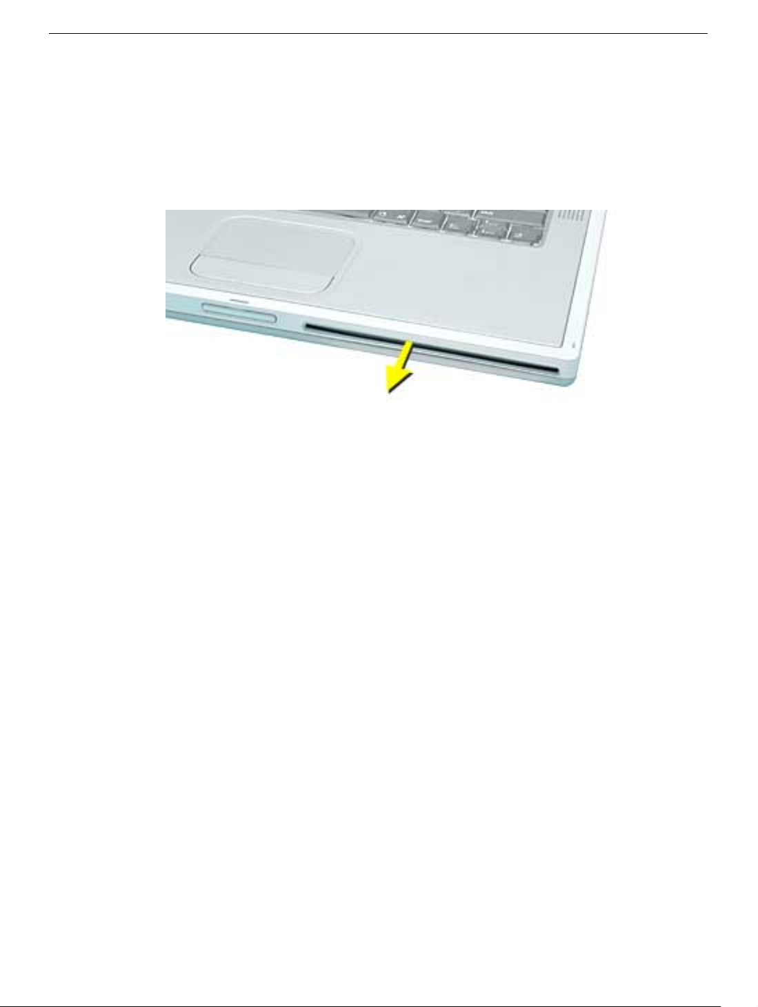
4. Install the replacement inverter board onto the optical drive.
5. Reassemble and test the computer.
Important: Make sure the bottom case is installed correctly. If the slot-load area is
slightly bowed, carefully pull the bottom edge of the slot until it clicks into place and
becomes flush with the bottom case.
Important: Check the operation of the optical drive. If the drive is installed
incorrectly, the optical drive mechanism might not spin correctly and will result in
mechanical noise when playing a disc.
PowerBook G4 (DVI) Inverter Board - 3
Page 61

PowerBook G4 (DVI)
Modem
Replacement Instructions
The following instructions explain how to replace the modem in the PowerBook G4 (DVI)
computer.
Tools
• Black stick (nylon probe tool 922-5065) or other ESD-safe, non-marring tool
• Torx T6 screwdriver
• Torx T8 screwdriver
Preliminary Steps
Before you begin, remove the following:
• Battery
• Keyboard
• Bottom case (remove in step 2)
© 2002 Apple Computer, Inc. All rights reserved. Updated: 2002-04-29
Page 62
Procedure
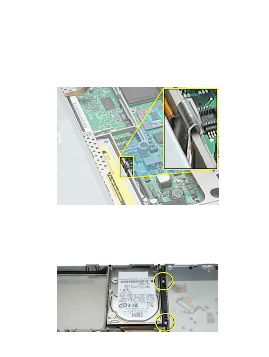
1. With the display open and the keyboard removed, locate and remove the EMI clip that
secures the optical drive’s flex cable to the rib frame. Side until reassembling the
computer.
Replacement Note: When reassembling the computer, ensure that the EMI clip
captures the tab on the flex cable and holds it against the rib frame.
2. Remove the bottom case.
Important: With the bottom case removed, be careful if turning over the computer.
Some components could become loose and fall out.
3. Remove the two T8 screws that secure the hard drive mounting bracket and remove
the bracket.
PowerBook G4 (DVI) Modem - 2
Page 63
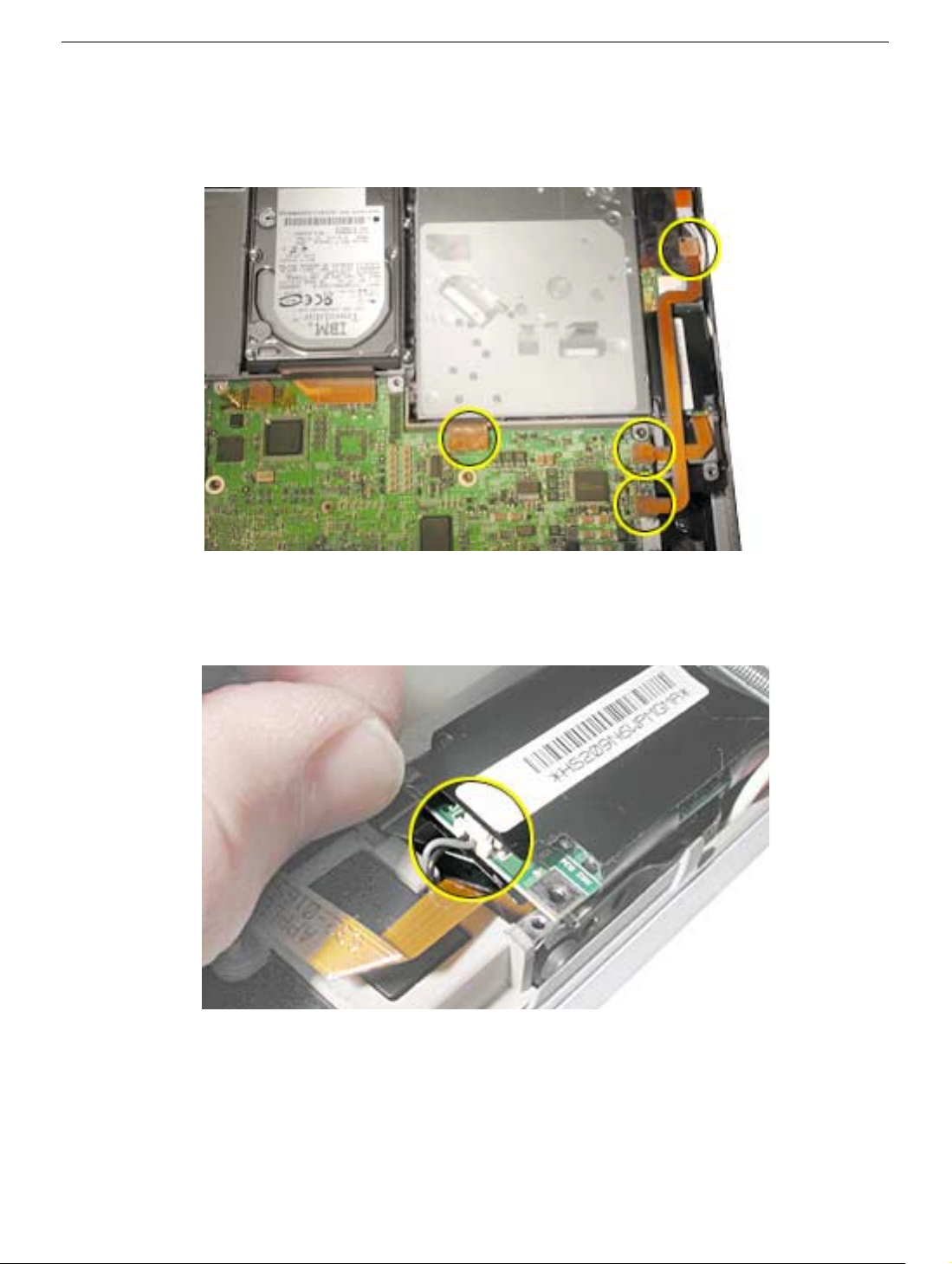
4. Disconnect the inverter board flex cable from the inverter board and logic board.
5. Disconnect the optical drive and modem flex cables from the logic board.
6. Remove the two T6 screws that secure the modem.
7. Lift up the end of the modem slightly and disconnect the 2-pin cable connector.
PowerBook G4 (DVI) Modem - 3
Page 64
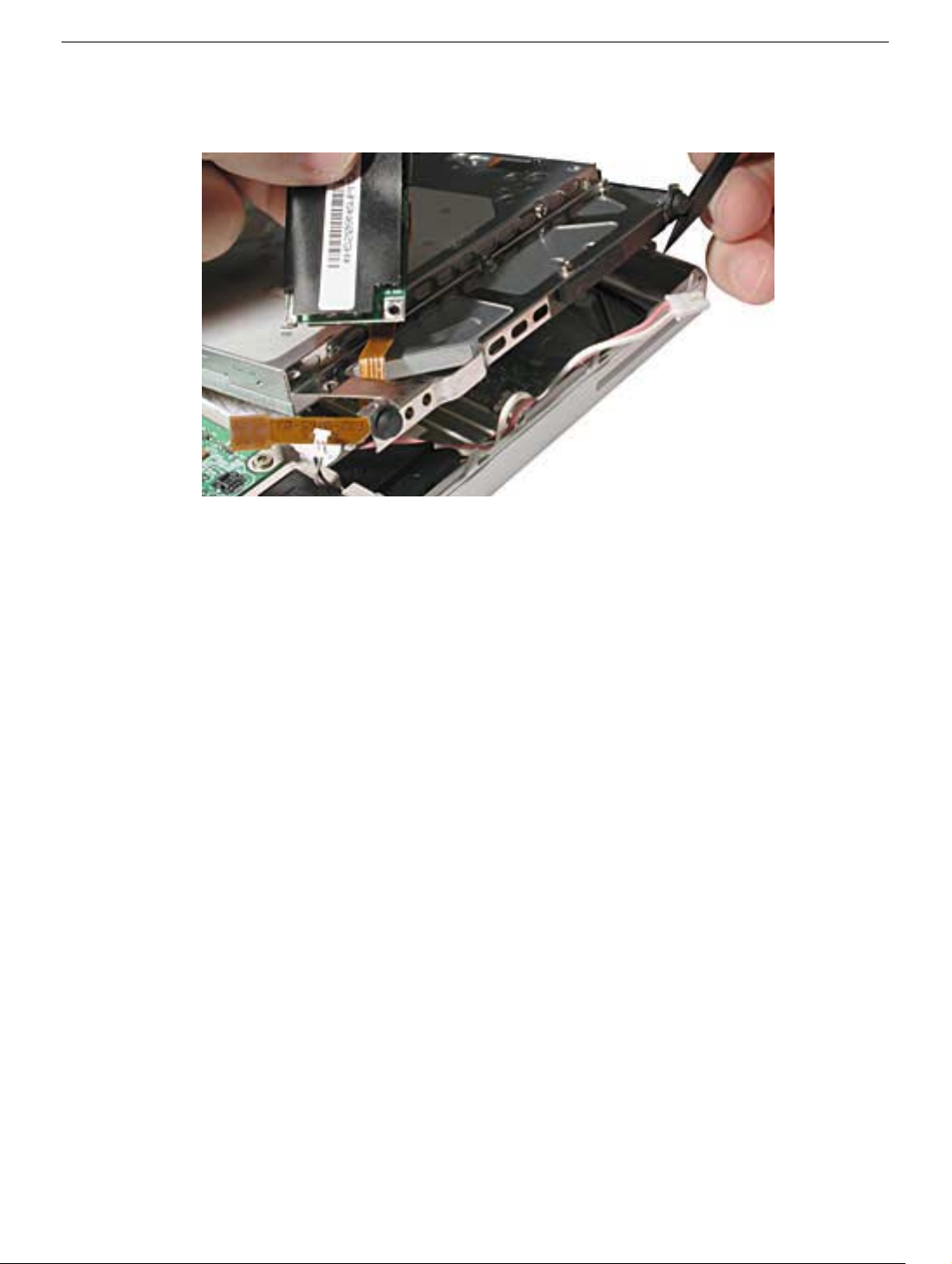
8. Use a thin tool to lift the optical drive slightly, then deroute the modem flex cable.
9. If the modem flex cable is not damaged, remove it and transfer it to the replacement
modem.
10. Install the replacement modem. Avoid putting pressure on or stressing the modem
board during installation.
11. To replace the optical drive, carefully guide the rubber stoppers on the outer side of
the drive past the edge of the computer case.
Warning: To prevent damage to the optical drive, handle the drive only by the
corners. Do not press on the body of the drive.
Important: When the rubber stoppers are inserted, push down on all four corners of
the drive to verify that the drive is level and secure.
PowerBook G4 (DVI) Modem - 4
Page 65
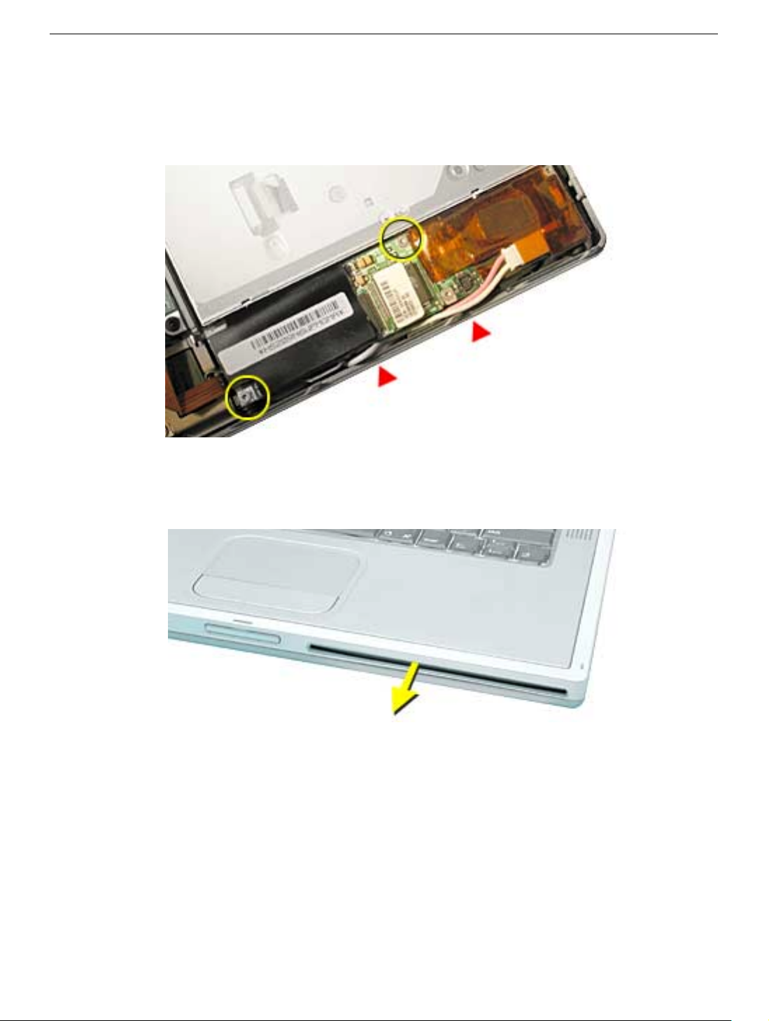
12. Reassemble and test the computer.
Replacement Note: When reinstalling the optical drive, ensure that the bulb wire
cable is safely within the case edge so that it will not get pinched by the bottom case.
Important: Make sure the bottom case is installed correctly. If the slot-load area is
slightly bowed, carefully pull the bottom edge of the slot until it clicks into place and
becomes flush with the bottom case.
Important: Check the operation of the optical drive. If the drive is installed
incorrectly, the optical drive mechanism might not spin correctly and will result in
mechanical noise when playing a disc.
PowerBook G4 (DVI) Modem - 5
Page 66

PowerBook G4 (DVI)
Combination DVD-ROM/CD-RW Optical Drive
Replacement Instructions
The following instructions explain how to replace the combination DVD-ROM/CD-RW
optical drive in the PowerBook G4 (DVI) computer.
Tools
• Black stick (nylon probe tool 922-5065) or other ESD-safe, non-marring tool
• Torx T6 screwdriver
• Torx T8 screwdriver
Preliminary Steps
Before you begin, remove the following:
• Battery
• Keyboard
• Bottom case (remove in step 2)
© 2002 Apple Computer, Inc. All rights reserved. Updated: 2002-04-29
Page 67
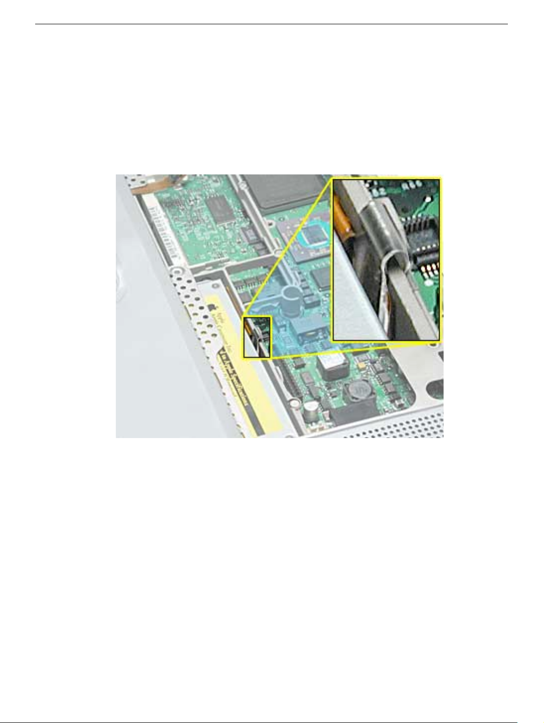
Procedure
1. With the display open and the keyboard removed, locate and remove the EMI clip that
secures the optical drive’s flex cable to the rib frame. Set it aside for installation of the
replacement drive.
Replacement Note: When installing the replacement drive, ensure that the EMI clip
captures the tab on the flex cable and holds it against the rib frame.
2. Remove the bottom case.
Important: With the bottom case removed, be careful if turning over the computer.
Some components could become loose and fall out.
PowerBook G4 (DVI) Combination DVD-ROM/CD-RW Optical Drive - 2
Page 68
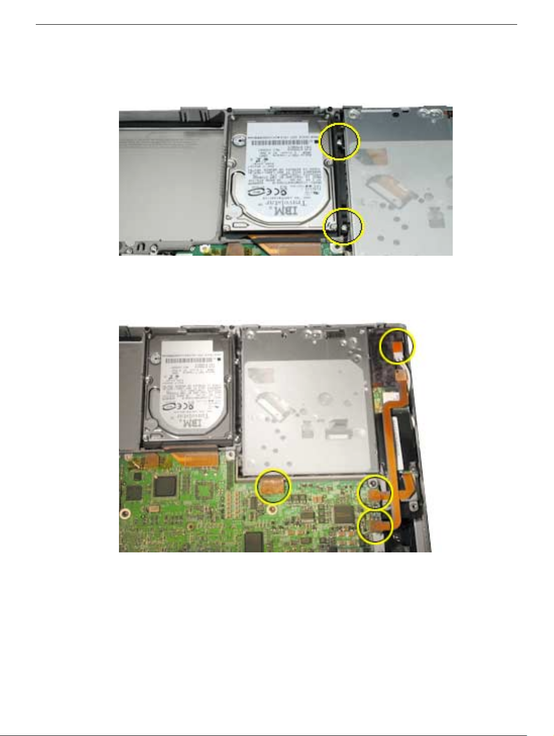
3. Remove the two T8 screws that secure the hard drive mounting bracket and remove
the bracket.
4. Disconnect the inverter board flex cable from the inverter board and logic board.
5. Disconnect the optical drive and modem flex cables from the logic board.
PowerBook G4 (DVI) Combination DVD-ROM/CD-RW Optical Drive - 3
Page 69
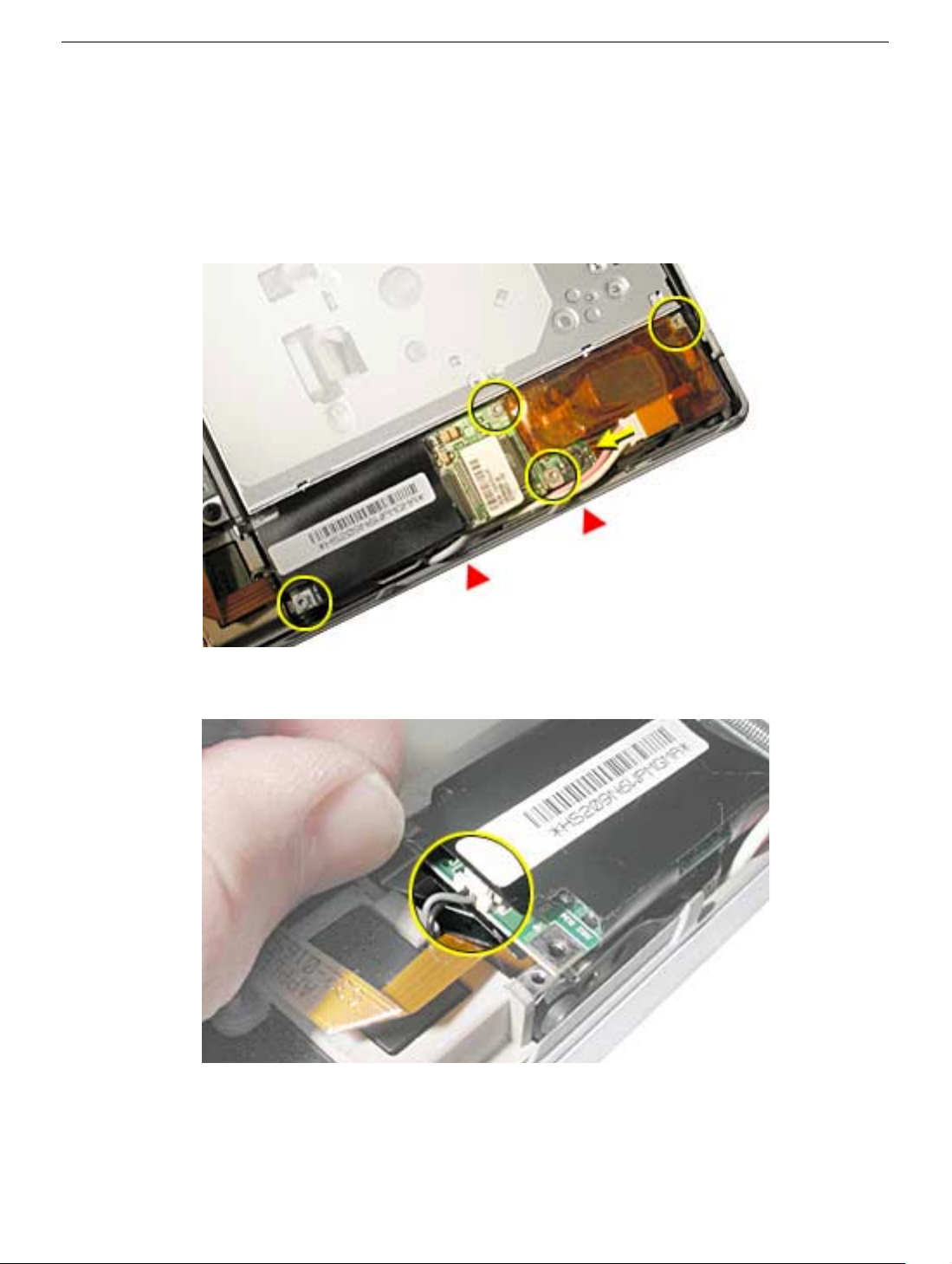
6. Disconnect the bulb wire cable from the inverter board.
7. Remove the four T6 screws that secure the modem and the inverter board and remove
the inverter board.
Replacement Note: When reinstalling the replacement optical drive, ensure that the bulb
wire cable is safely within the case edge so that it will not get pinched by the bottom case.
8. Lift up the end of the modem slightly and disconnect the 2-pin cable connector.
PowerBook G4 (DVI) Combination DVD-ROM/CD-RW Optical Drive - 4
Page 70
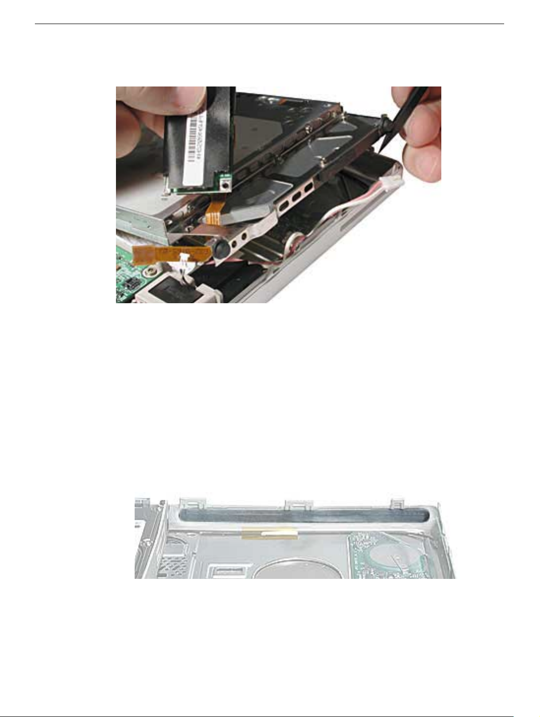
9. Use a thin tool to lift the optical drive slightly, then deroute the modem flex cable.
10. Warning: To prevent damage to the optical drive, handle the drive only by the
corners. Do not press on the body of the drive.
To remove the optical drive, pull the drive to the right, away from the hard drive, to
release the long rubber stopper from the rib frame.
11. Important: If you notice that the felt strip for the slot-load area is torn or damaged,
replace the felt strip with a new one before replacing the optical drive. Follow the
instructions below to replace the felt strip:
Locate the felt strip that came with the replacement drive. Before you remove the old
felt strip, note the alignment of the felt strip over the slot-load area in the inner top
case.
PowerBook G4 (DVI) Combination DVD-ROM/CD-RW Optical Drive - 5
Page 71
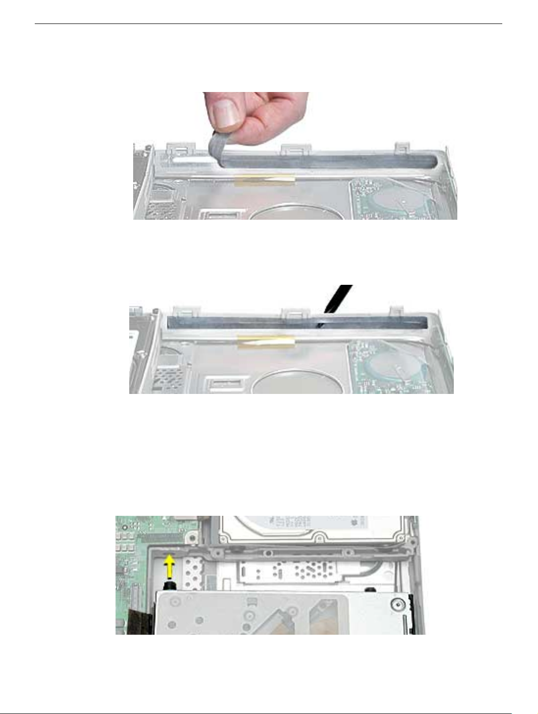
Peel off the felt strip from the inner top case. If there is any residual adhesive on the
top case, rub it away.
Apply the new felt strip to the slot-load area. Make sure the new felt strip lies flat. Use
a black stick to run the length of the slot to make sure that the felt strip does not block
any of the slot.
12. Install the modem and inverter board onto the replacement optical drive. Again,
handle the optical drive only by the corners. Do not press on the body of the drive.
13. To install the replacement optical drive, first insert the longer stopper on the inner side
of the drive into the opening on the rib frame. Ensure that the other inner stopper rests
securely in its space on the frame. Then while holding the inner side of the drive in
place, carefully guide the rubber stoppers on the outer side of the drive past the edge
of the computer case.
Important: When the rubber stoppers are inserted, push down on all four corners of
the drive to verify that the drive is level and secure.
PowerBook G4 (DVI) Combination DVD-ROM/CD-RW Optical Drive - 6
Page 72
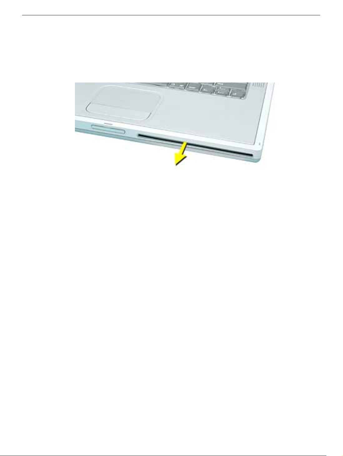
14. Reassemble and test the computer.
Important: Make sure the bottom case is installed correctly. If the slot-load area is
slightly bowed, carefully pull the bottom edge of the slot until it clicks into place and
becomes flush with the bottom case.
Important: Check the operation of the optical drive. If the drive is installed
incorrectly, the optical drive mechanism might not spin correctly and will result in
mechanical noise when playing a disc.
PowerBook G4 (DVI) Combination DVD-ROM/CD-RW Optical Drive - 7
Page 73

PowerBook G4 (DVI)
Backup Battery
Replacement Instructions
The following instructions explain how to replace the backup battery in the PowerBook G4
(DVI) computer.
Tools
• Black stick (nylon probe tool 922-5065) or other ESD-safe, non-marring tool
Preliminary Steps
Before you begin, remove the following:
• Battery
• Optical drive
© 2002 Apple Computer, Inc. All rights reserved. Updated: 2002-04-29
Page 74
Procedure
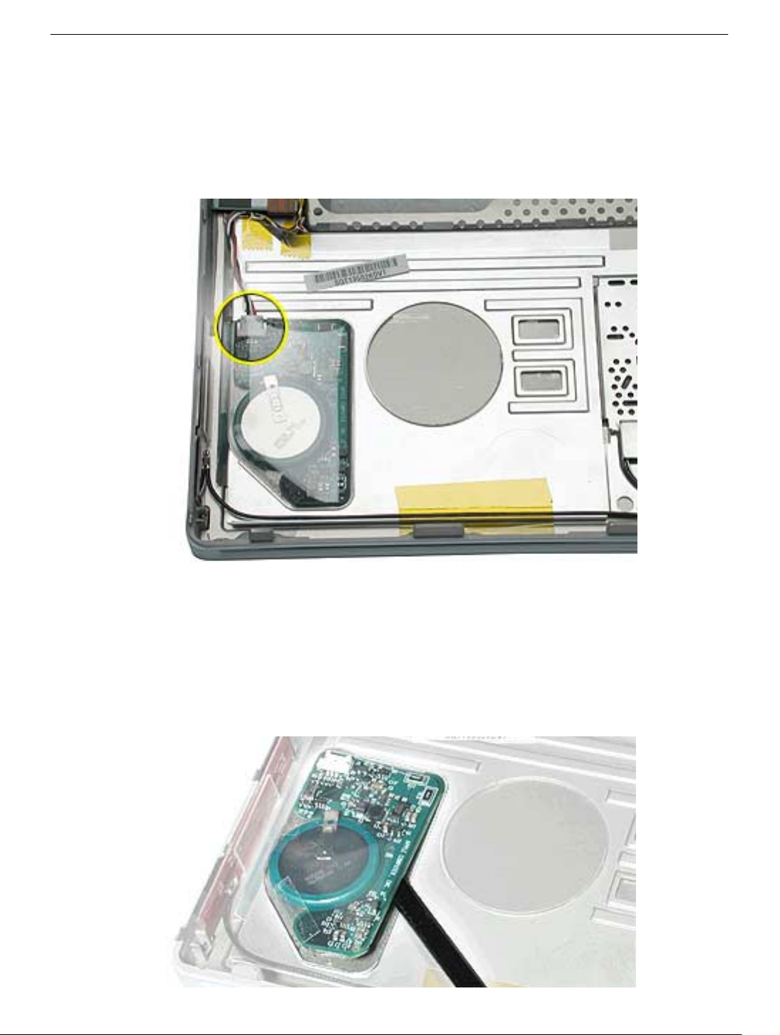
1. Disconnect the backup battery cable from the backup battery.
Note: If the cable connector gets caught on the ridged area of the top case, use a
black stick to raise up the backup battery and then disconnect the cable.
2. Note: The backup battery is compressed between two thin plastic sheets. The battery
is held in place with adhesive on the lower plastic sheet.
Slide a black stick under and along the edge of the backup battery. Pry up the
backup battery so that the entire battery—including the lower plastic sheet—is
removed from the inner top case.
Warning: The ridged area of the top case is sharp.
PowerBook G4 (DVI) Backup Battery - 2
Page 75
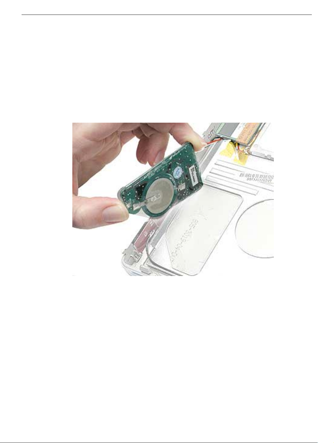
3. If there is any adhesive left on the surface of the inner top case, use a black stick to
rub it away. Do not use solvents.
Note: When installing the replacement backup battery, make sure the inner top case
is clean and free of debris.
4. Peel off the cover sheet from the bottom surface of the replacement backup battery to
expose the adhesive.
5. When positioning the replacement backup battery on the inner top case, make sure
the battery fits within the ridged battery area of the inner top case.
6. Install the replacement backup battery, and reassemble and test the computer.
PowerBook G4 (DVI) Backup Battery - 3
Page 76

PowerBook G4 (DVI)
Logic Board
Replacement Instructions
The following instructions explain how to replace the logic board in the PowerBook G4
(DVI) computer.
Important: Check the “Heat Exchanger Upgrade” and the “Check for PowerBook G4 (DVI)
867 MHz Upgrade” chapters of this manual for possible configuration changes.
Tools
• Torx T8 screwdriver
• Black stick (nylon probe tool 922-5065) or other ESD-safe, non-marring tool
• Razor blade
• Needle nose pliers (optional)
Note: To organize the screws you remove from the computer, use a tray with divided
compartments (such as a plastic ice cube tray).
Preliminary Steps
Before you begin, remove the following:
• Battery
• Keyboard
Remove the following in step 4:
• Bottom case
• AirPort Card (if installed)
© 2002 Apple Computer, Inc. All rights reserved. Updated: 14 October 2003
Page 77
Procedure
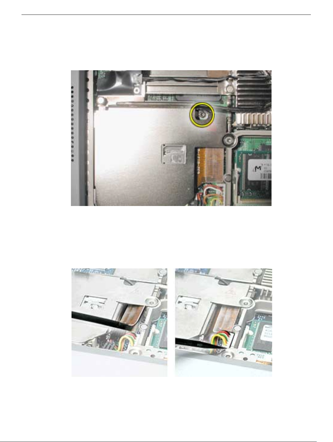
1. With the display open and the keyboard removed, remove the T8 screw near the heat
pipe.
2. Disconnect the PC card flex cable connector and the keyed battery connector.
Important: If the battery connector has not been disconnected before, the keyed
connector may be tight. If necessary, use a black stick or needle nose pliers to
loosen one side of the connector and then the other side. Then insert the black stick
under the cables to pry up and disconnect the connector.
Replacement Note: When reassembling the computer, tuck down the battery cables
so they do not get in the way when the keyboard is installed.
PowerBook G4 (DVI) Logic Board - 2
Page 78
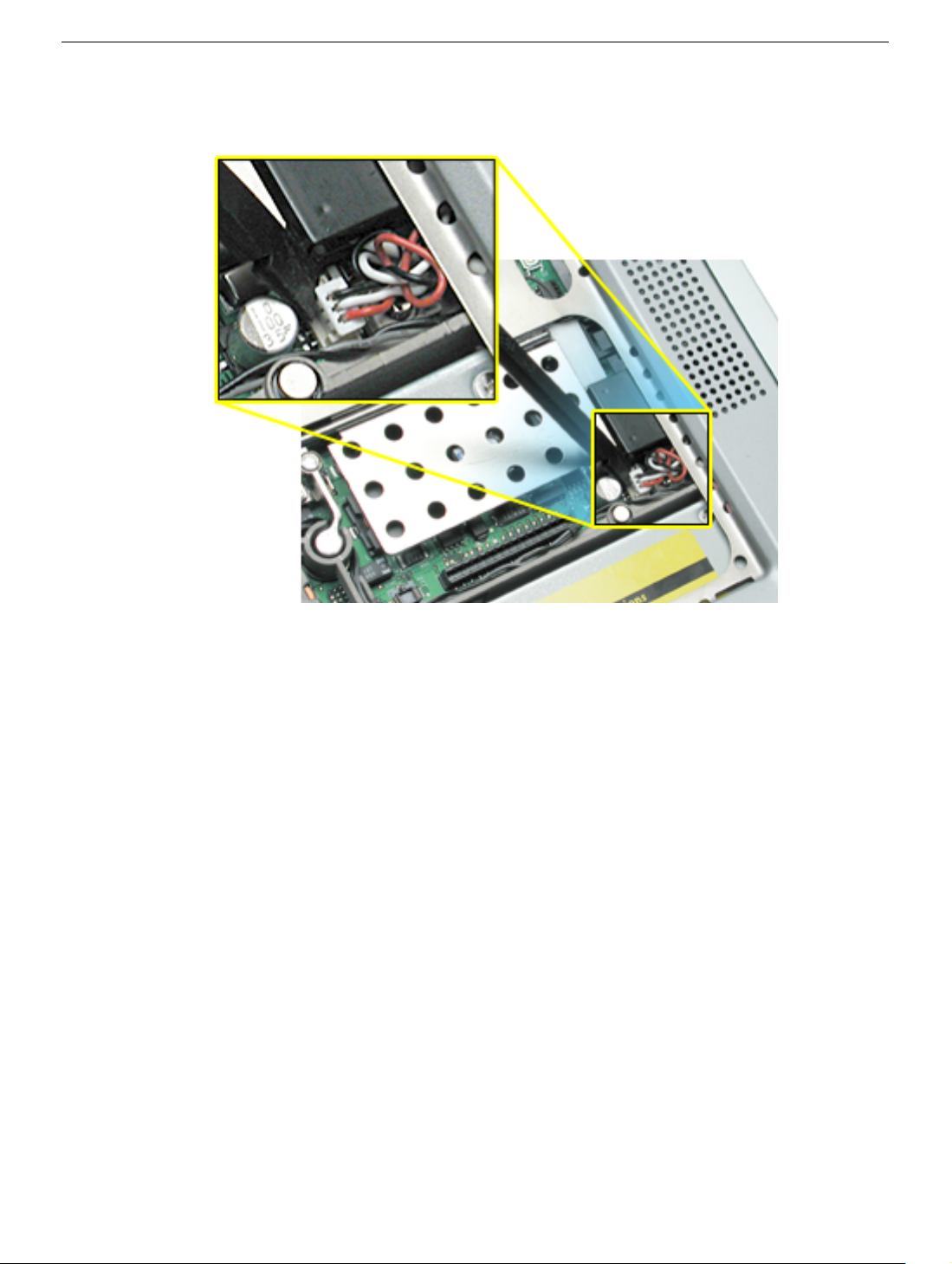
3. Disconnect the 3-pin backup battery connector from the logic board.
4. Remove the bottom case.
Important: With the bottom case removed, be careful when turning over the
computer. Some components could become loose and fall out.
PowerBook G4 (DVI) Logic Board - 3
Page 79
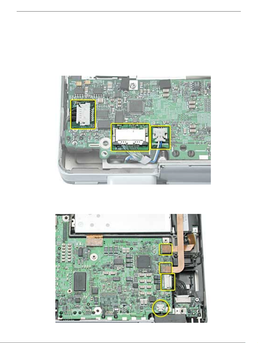
5. Warning: The thin cables connected to the LVDS (low voltage data signal)
connector are extremely delicate. Do not pull or pinch the LVDS cables. Be
especially careful when working near cables that attach to the display. If any of
these cables are damaged, the entire display module must be replaced.
At the left side of the logic board, disconnect the 2-pin sleep LED cable connector,
the LVDS connector, and the 6-pin audio connector.
6. At the right side of the logic board, disconnect the 2-pin power button cable connector,
the DC-in board cable connector, and the inverter board and modem flex cable
connectors.
PowerBook G4 (DVI) Logic Board - 4
Page 80
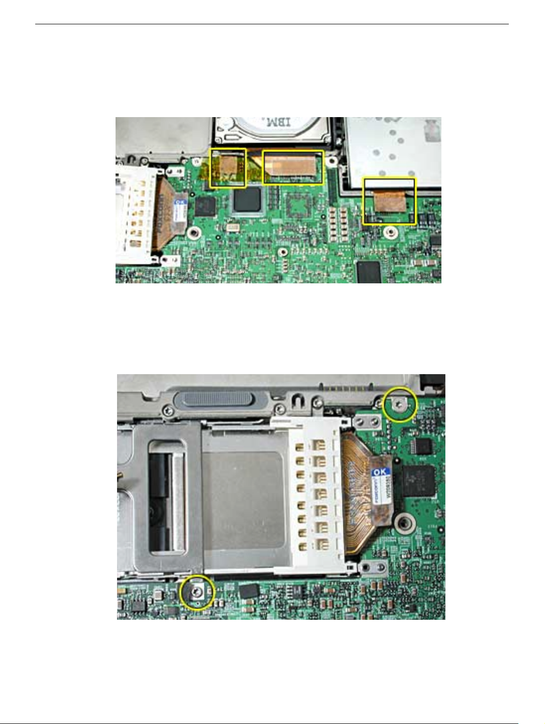
7. Disconnect the trackpad, hard drive and optical drive flex cable connectors.
Note: If tape is covering the trackpad connector, reserve the tape for installation of
the replacement logic board.
8. Remove the T8 screw on the edge of the logic board near the battery well.
Important: Install this screw first when installing the replacement logic board. This
screw helps the logic board align properly to the rib frame.
9. Remove the T8 screw securing the PC card cage.
PowerBook G4 (DVI) Logic Board - 5
Page 81
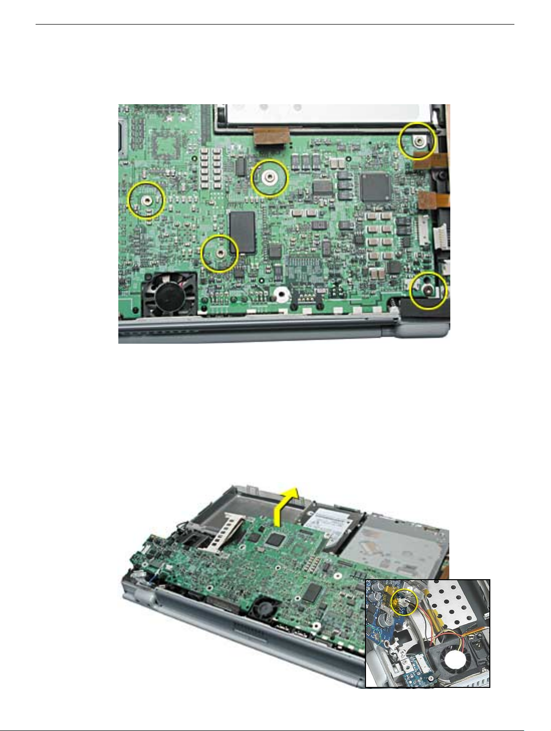
10. Remove the five identical (bronze colored) T8 screws.
Note: When reassembling the computer, do not overtighten the screws.
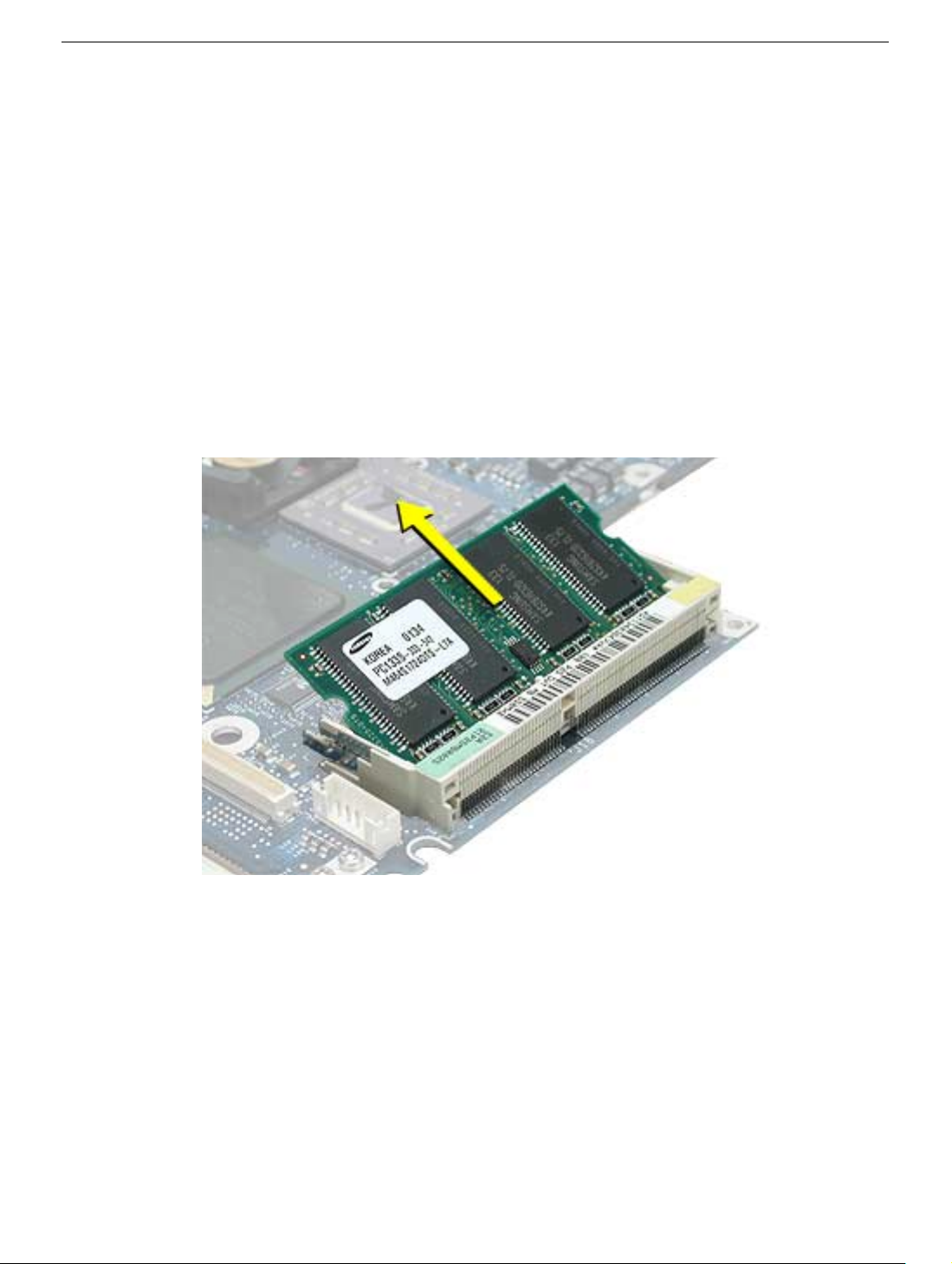
11. Grasp the logic board near the AirPort Card carrier and gently lift the board up and
out, as shown below, being careful where it catches on ports, back panel mesh liner,
and disconnected cables.
If necessary, open the panel door and press on the ports to free the logic board from
the back panel.
Important: If a secondary fan is installed, lift the board just enough to access and
disconnect the fan’s connector on the logic board before removing the board.
PowerBook G4 (DVI) Logic Board - 6
Page 82
Replacement Note: When reassembling the computer, make sure the replacement
logic board ports align completely with the openings in the back panel.
Replacement Note: When positioning the replacement logic board into the
computer, check that cables and connectors do not get caught under the board. Tilt
the logic board toward the back panel, and place the following cables into the
notches in the board:
• Power switch cable (reapply tape over the cable, if applicable)
• Sleep LED cable
• LVDS cable
• Audio cable
12. Remove existing memory cards from the logic board for installation on the
replacement logic board. Carefully spread the end brackets to allow the card to raise
up, then pull out.
PowerBook G4 (DVI) Logic Board - 7
Page 83
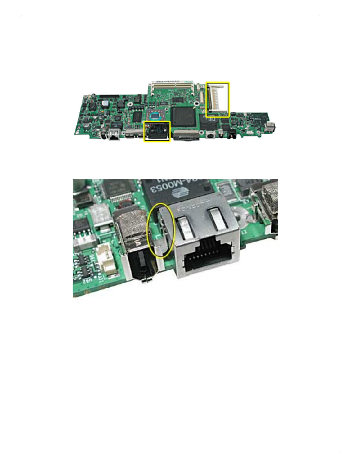
13. Install new, or transfer the following from the old logic board to the replacement logic
board:
• AirPort card carrier
• RJ-11 port
• U-shaped EMI clip between the FireWire and Ethernet ports
PowerBook G4 (DVI) Logic Board - 8
Page 84
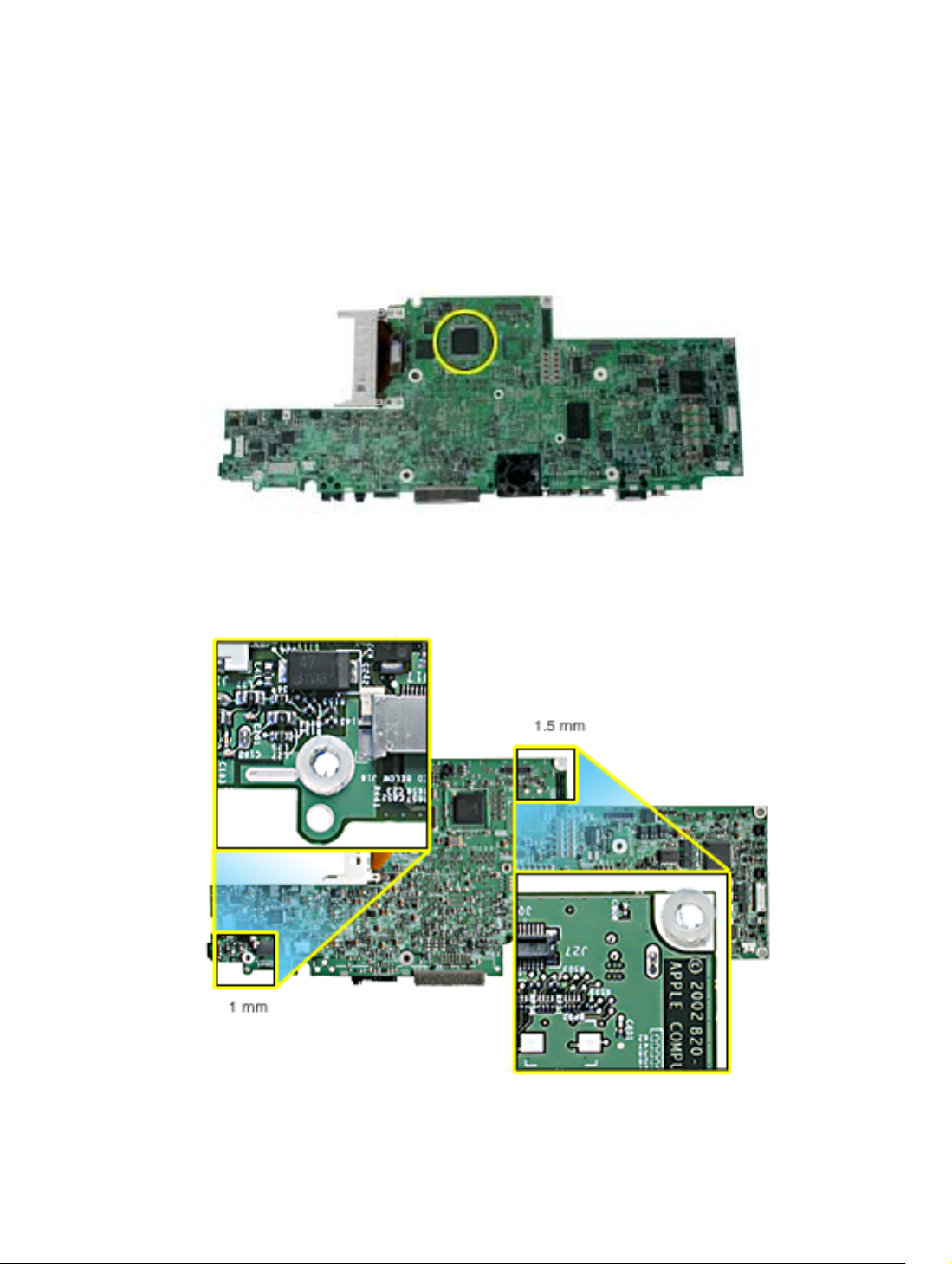
• Rectangular plastic standoff around the agere chip
Important: If transferring from the old board, use a razor knife to remove. Be very
careful not to damage board components.
Warning: Verify that the standoff installs flat and does not get caught or raised
up on the perimeter edge of the chip.
• Plastic 1 mm and 1.5 mm washers around the screw holes, shown. Center and
press into place.
PowerBook G4 (DVI) Logic Board - 9
Page 85
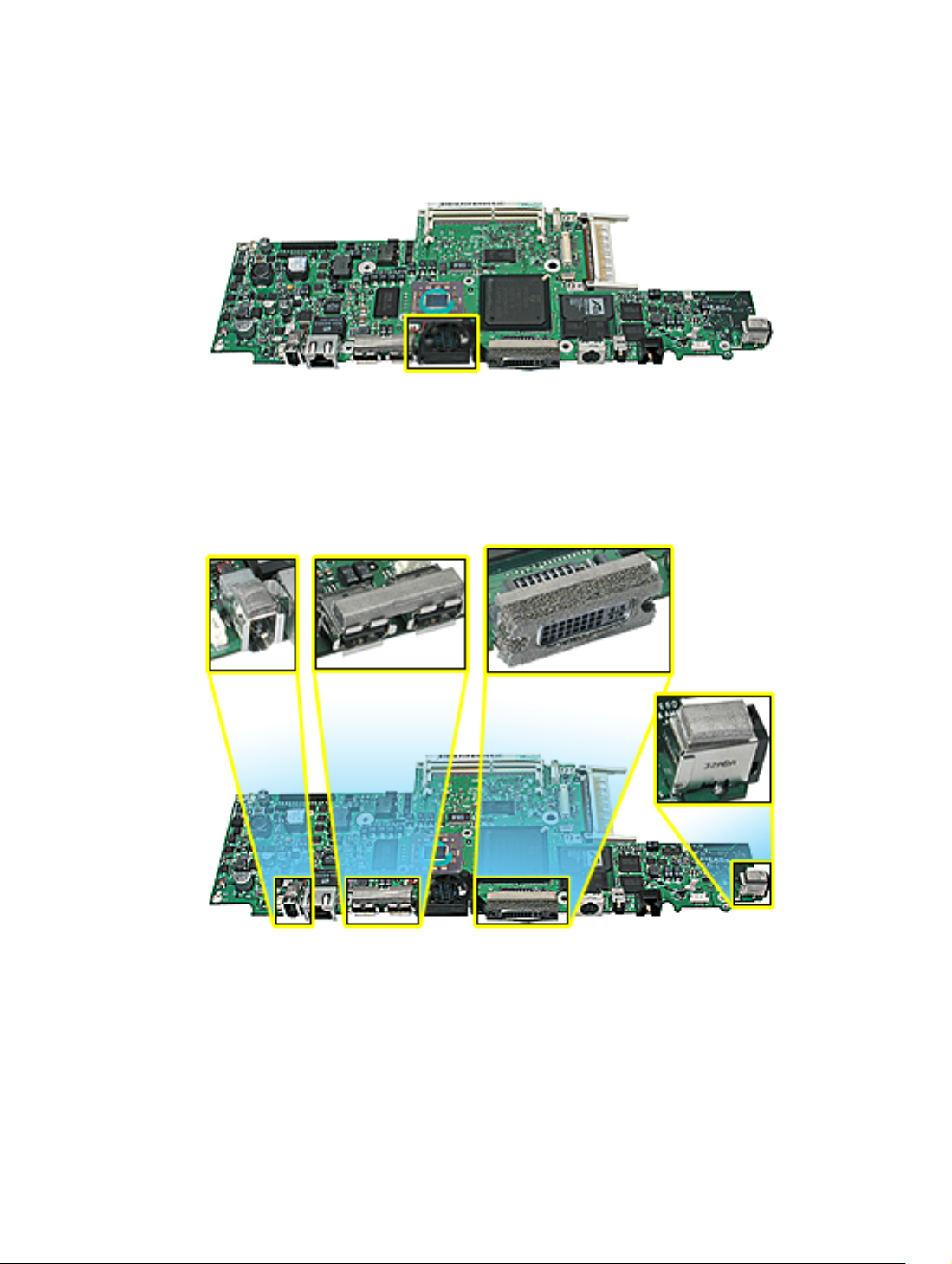
14. Install the following onto the replacement logic board:
• Primary fan
• EMI gaskets to the USB ports, FireWire port, DVI-I port, and headphone port, (use
an I/O EMI gasket kit)
PowerBook G4 (DVI) Logic Board - 10
Page 86
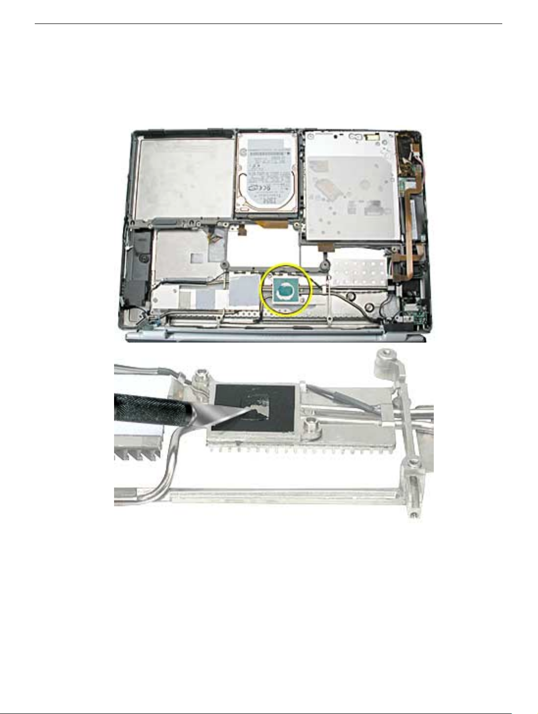
15. Check that the heat exchanger has three rectangular thermal interface pads in place.
If the pads are missing or damaged, replace the heat exchanger.
16. Use a razor blade or black stick to gently scrape away any residual thermal transfer
material on the heat exchanger on the surface that mates with the microprocessor.
PowerBook G4 (DVI) Logic Board - 11
Page 87
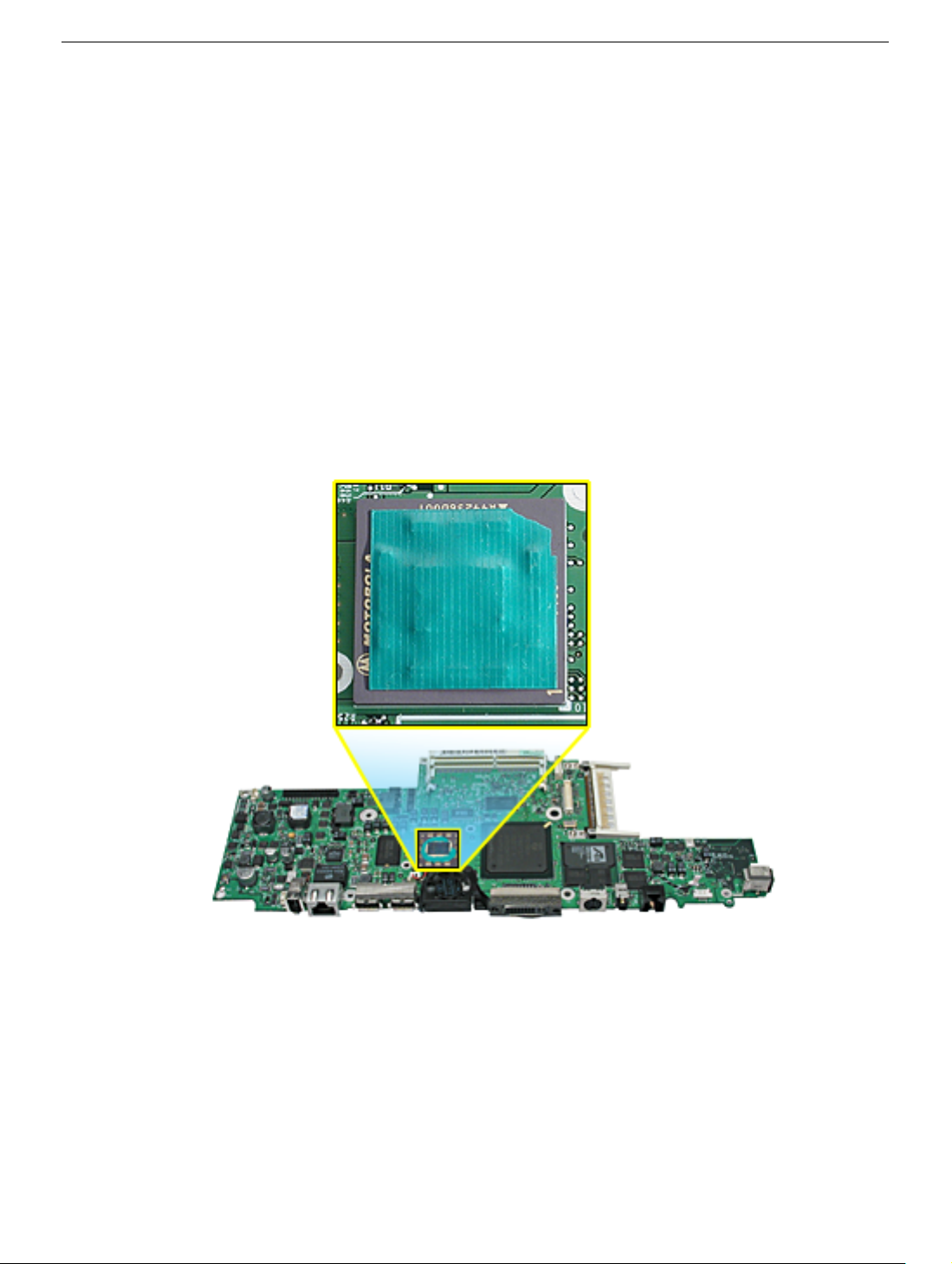
17. Important: If you have removed the logic board to access another part, and you will
be placing the original logic board back in the computer, use a black stick to gently
scrape away any residual thermal transfer material from the microprocessor chip on
the logic board.
Warning: When scraping away the thermal transfer material from the
microprocessor chip, be careful not to nick the microprocessor chip.
18. On the replacement logic board, center new thermal transfer material over the epoxy
cap on the microprocessor chip. Press it into place.
Note: The thermal material pads break easily. Use care when removing the pad from
its packaging and when handling, to avoid damage.
Important: Do not install thermal material on the logic board chip if replacing the
heat exchanger and thermal material is already installed on the chip mating surface.
PowerBook G4 (DVI) Logic Board - 12
Page 88
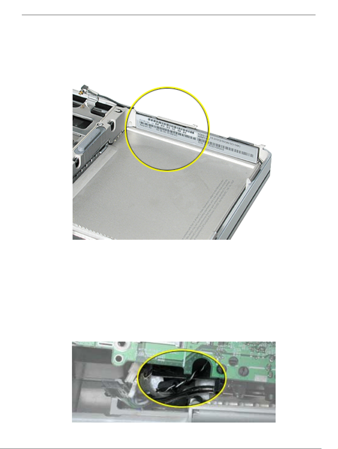
19. If included with the logic board, remove the new Ethernet ID label (possibly on the
static bag or on the board’s memory card bracket), peel off the adhesive protector and
attach the label, right side up, over the Ethernet ID and bar code on the ID plate inside
the battery well.
20. Install the replacement logic board, and reassemble and test the computer.
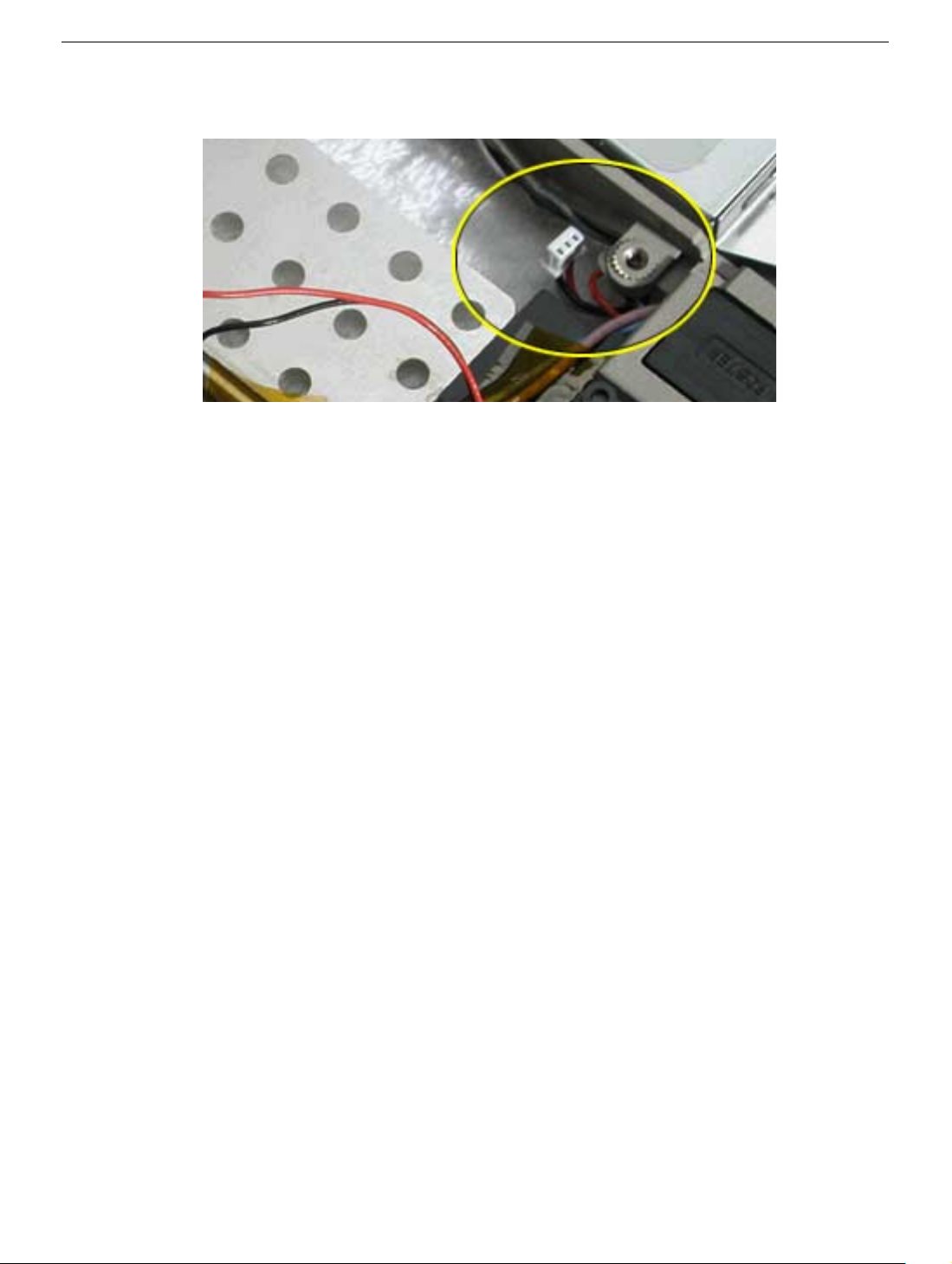
Replacement Note: When replacing the logic board, the RJ-11 cable and backup
battery wire connectors must be routed, as shown below, so that they do not interfere
with the logic board replacement and can later be accessed through the keyboard
opening.
Ensure that optical drive’s flex cable has not been pulled out of the EMI clip, and that
the clip still secures the tab on the flex cable to the rib frame.
PowerBook G4 (DVI) Logic Board - 13
Page 89
21. Use appropriate diagnostics to test all ports, components and functions of the
computer.
PowerBook G4 (DVI) Logic Board - 14
Page 90

PowerBook G4 (DVI)
Primary Fan
Replacement Instructions
The following instructions explain how to replace the primary fan in the PowerBook G4
(DVI) computer.
Important: Check the “Check for PowerBook G4 (DVI) 867 MHz Upgrade” chapter of this
manual for possible configuration changes.
Tools
• Black stick (nylon probe tool 922-5065) or other ESD-safe, non-marring tool
• Razor blade
• Needle nose pliers
Preliminary Steps
Before you begin, remove the following:
• Battery
• Logic Board
© 2002 Apple Computer, Inc. All rights reserved. Updated: 2002-04-29
Page 91
Procedure
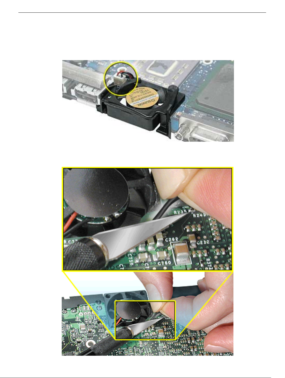
1. With the logic board removed from the computer, disconnect the fan connector from
the logic board.
2. Turn over the logic board, and locate the cone-shaped pin at the right corner of the
fan. Pull the rubber pin tight. Use a razor blade to cut through the rubber pin.
PowerBook G4 (DVI) Primary Fan - 2
Page 92
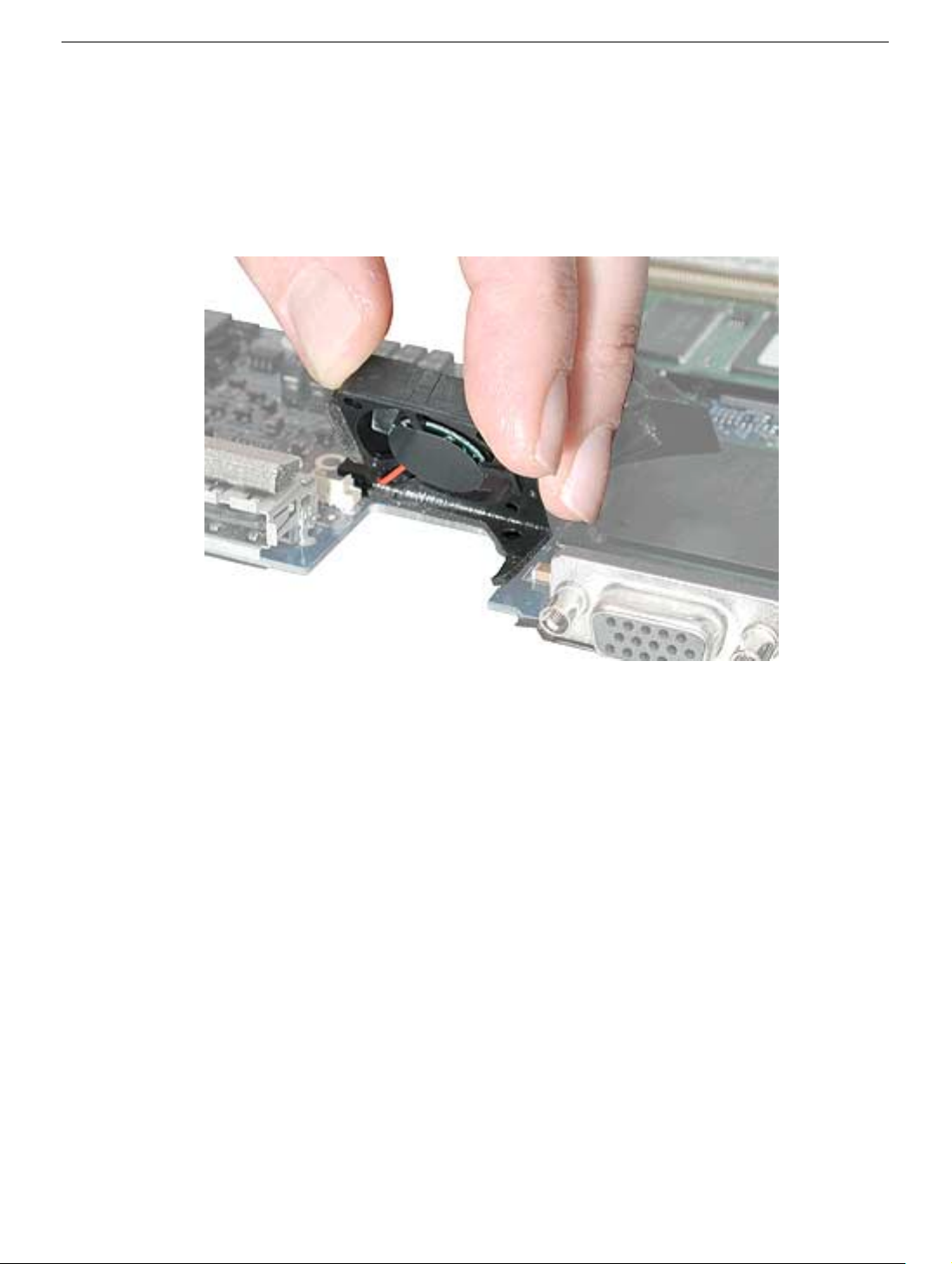
3. Turn over the logic board, and tilt up the fan to remove it completely from the logic
board.
Note: The fan is secured to the logic board by a spongy, rubber adhesive lining on
three sides of the bottom of the fan. If there is any adhesive stuck to the surface of
the logic board, remove it by rubbing it away. Do not use solvents.
4. When installing the replacement fan, first use a black stick to push the cone-shaped
rubber pin into the hole on the logic board. (If necessary, use needle nose pliers to pull
the rubber pin through to the other side of the logic board.) Then, peel away the
protective cover from the adhesive that lines the three sides of the fan. Align the fan
over the logic board opening and press the fan into place.
Important: Do not press on the center hub of the fan. Press only on the outside
edges of the fan housing.
Note: If the cone-shaped rubber pin is too long, use a razor blade to cut the extra
length.
5. With the replacement fan installed securely, and the fan connector connected to the
logic board, reassemble and test the computer.
PowerBook G4 (DVI) Primary Fan - 3
Page 93

PowerBook G4 (DVI)
Secondary Fan (or bracket)
Replacement Instructions
The following instructions explain how to replace the secondary fan (800 MHz logic board)
or bracket (667 MHz logic board) in the PowerBook G4 (DVI) computer.
Important: Check the “Heat Exchanger Upgrade” and the “Check for PowerBook G4 (DVI)
867 MHz Upgrade” chapters of this manual for possible configuration changes.
Tools
• Black stick (or other nonconductive nylon or plastic tool)
• Torx T6 screwdriver
Preliminary Steps
Before you begin, remove the following:
• Battery
• Logic Board (if a secondary fan is installed, disconnect its connector from the logic
board while removing the logic board)
© 2002 Apple Computer, Inc. All rights reserved. Updated: 2002-04-29
Page 94
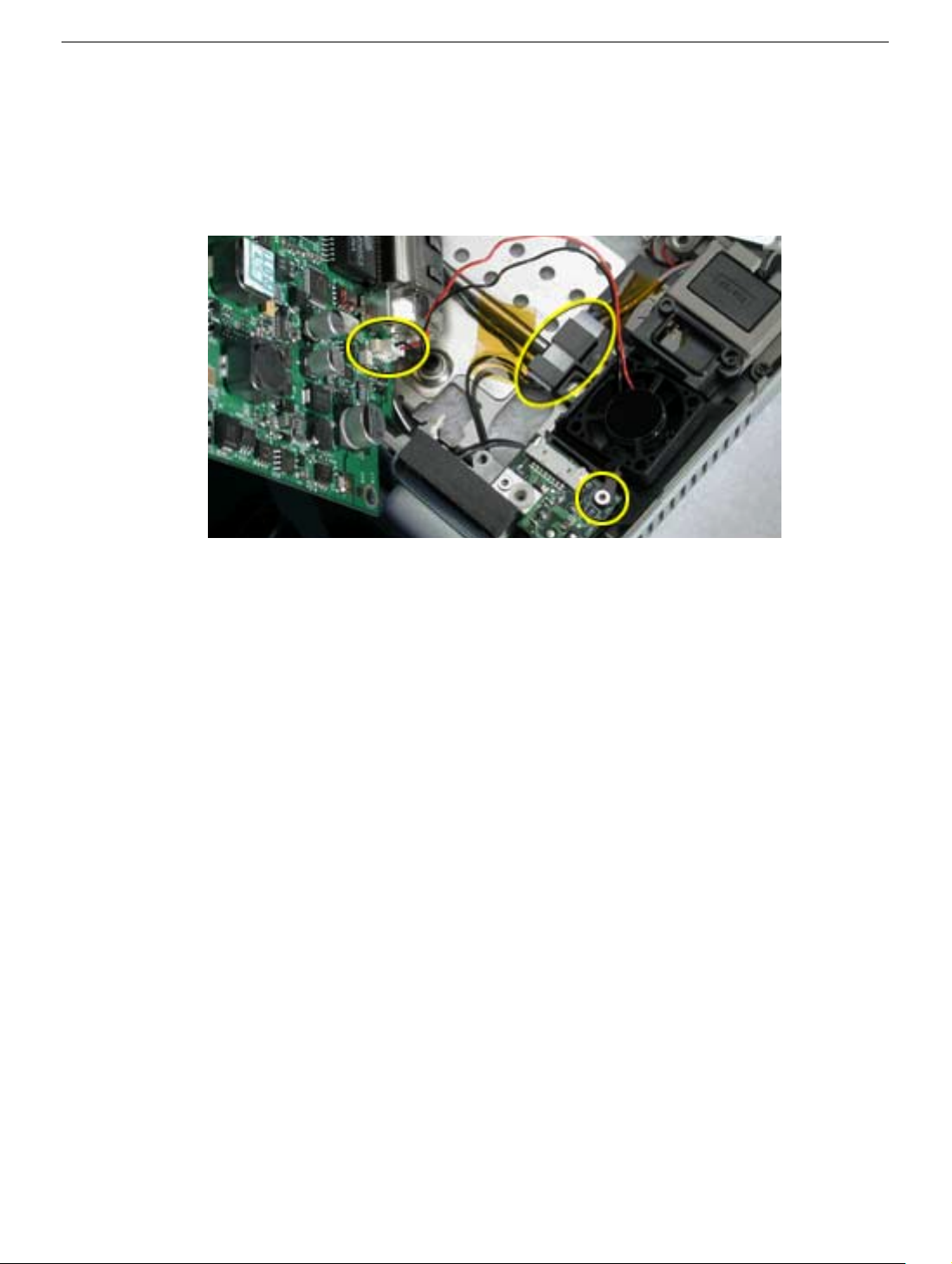
Procedure
1. Remove the T6 screw from the fan bracket.
2. If a secondary fan is installed, disconnect its connector from the logic board while
removing the logic board. Lift out the fan bracket or fan assembly.
Replacement Note: Ensure that the fan bracket captures and secures the bulb wire
connector, as shown.
PowerBook G4 (DVI) Secondary Fan - 2
Page 95

PowerBook G4 (DVI)
PC Card Cage
Replacement Instructions
The following instructions explain how to replace the PC card cage in the PowerBook G4
(DVI) computer.
Tools
• Torx T8 screwdriver
• 4 mm Hex socket or wrench
• 5 mm Hex socket or wrench
Preliminary Steps
Before you begin, remove the following:
• Battery
• Keyboard
• Logic board
© 2002 Apple Computer, Inc. All rights reserved. Updated: 2002-04-29
Page 96
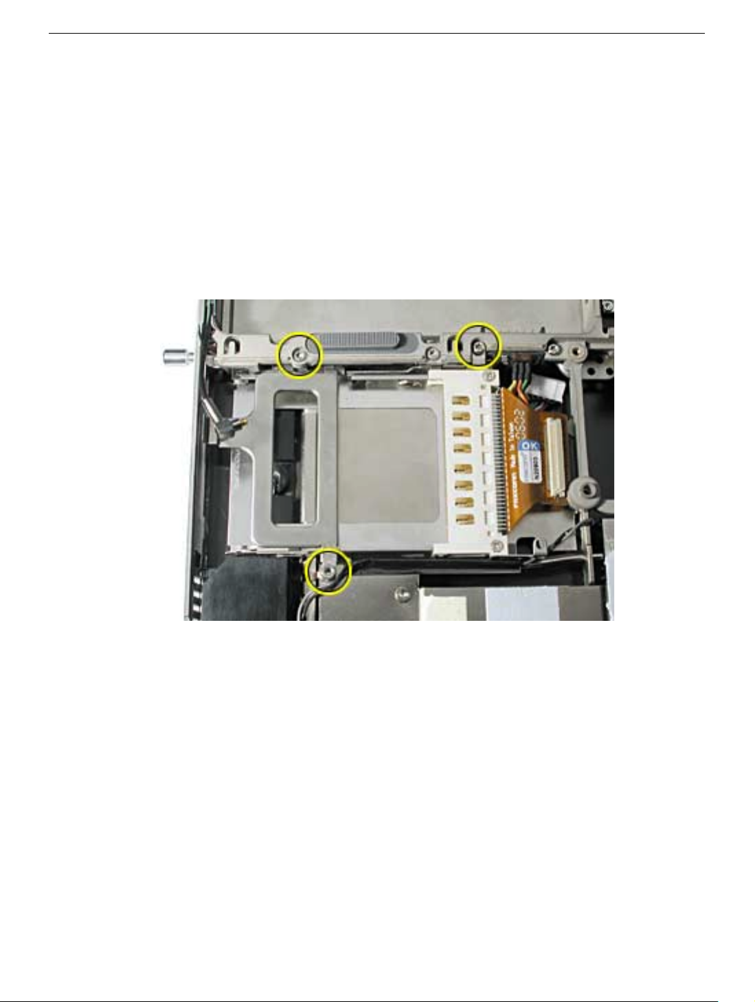
Procedure
1. Remove the two screws that attach the PC card cage to the rib frame. (The longer
screw is next to the battery connector.)
2. To remove the 4 mm hex nut that secures the PC card cage to the heat exchanger,
you may want to use a finger to support the 5 mm (magnetic) hex screw underneath
the nut to prevent the screw from falling out of the screw hole.
Loosen and remove the hex nut. Remove the PC card cage, being careful where it
can catch on the PC card eject button. Then, reattach the hex nut temporarily to the
hex screw.
PowerBook G4 (DVI) PC Card Cage - 2
Page 97
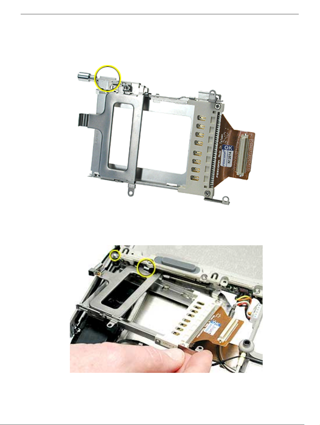
3. Check that the replacement PC card cage includes a clear plastic shim on the outer
frame near the PC card eject button. If the shim is not there, transfer the shim from the
old PC card cage to the replacement PC card cage.
4. When installing the replacement PC card cage, ensure that the metal flange that is
closest to the PC card eject button goes underneath the rib frame and metal liner at
the battery latch.
5. Install the replacement PC card cage, and reassemble and test the computer.
PowerBook G4 (DVI) PC Card Cage - 3
Page 98

PowerBook G4 (DVI)
Rib Frame and Heat Exchanger
Replacement Instructions
The following instructions explain how to replace the rib frame and the heat exchanger in
the PowerBook G4 (DVI) computer.
Important: Check the “Heat Exchanger Upgrade” and the “Check for PowerBook G4 (DVI)
867 MHz Upgrade” chapters of this manual for possible configuration changes.
Warning: Make sure you carefully follow these instructions, especially when
working near cables that attach to the display module. If any of the cables are
damaged, the entire display module must be replaced.
Tools
• Black stick (nylon probe tool 922-5065) or other ESD-safe, non-marring tool
• Torx T8 screwdriver
• Torx T6 screwdriver
Preliminary Steps
Before you begin, remove the following:
• Battery
• Keyboard
Remove the following in step 2:
• Bottom case
• Hard drive
• Optical drive
• Logic board
• PC card cage
• Secondary fan
© 2003 Apple Computer, Inc. All rights reserved. Updated: 14 October 2003
Page 99
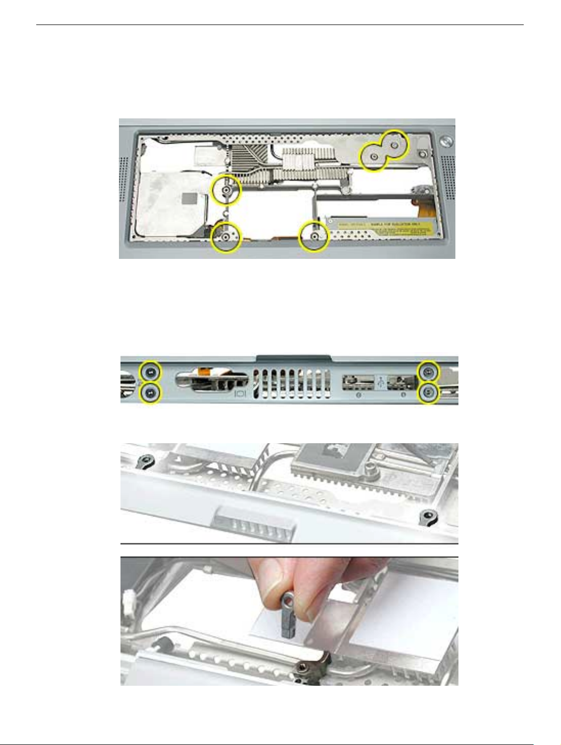
Procedure
1. With the display open and the keyboard removed, remove the five identical T8 screws
from the top case.
2. Remove the items listed in Preliminary Steps, to be removed in step 2.
Important: With the bottom case removed, be careful when turning over the
computer. Some components could become loose and fall out.
3. Open the I/O door, and remove the four identical T6 screws.
4. Lift out the two back panel mounts from the notches in the rib frame.
PowerBook G4 (DVI) Rib Frame and Heat Exchanger - 2
Page 100
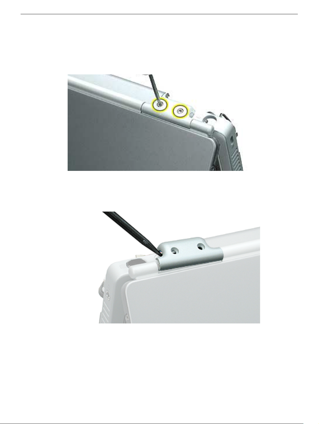
5. Close the computer to an approximate 45-degree angle, and stand it on a soft cloth
with the clutch covers facing up.
6. Remove the four identical T8 screws from the clutch covers (two screws on each
clutch cover).
7. Use a black stick to pry off the two clutch covers.
Note: Opening the display slightly may help to remove the covers.
PowerBook G4 (DVI) Rib Frame and Heat Exchanger - 3
 Loading...