


 Loading...
Service Source
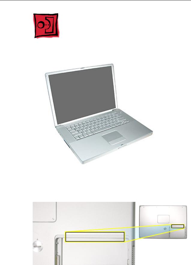
PowerBook G4 (15-inch 1.67/1.5GHz)
31 January 2005
© 2005 Apple Computer, Inc. All rights reserved.

Service Source
Take Apart
PowerBook G4 (15-inch 1.67/1.5GHz)
© 2005 Apple Computer, Inc. All rights reserved.
General Information
Overview
Identify the PowerBook G4 (15-inch 1.67/1.5GHz) by noting there is no AirPort Extreme card door in the battery well, as with previous 15-inch aluminum alloy body PowerBooks.
General Information |
PowerBook G4 (15-inch 1.67/1.5GHz) Take Apart - 1 |

Main feature differences from previous models:
•Built-in AirPort Extreme
•Illuminated keyboard on all models
•Built-in fiber optic backlit keyboard—the fiber-optic mat has been replaced with a light panel integrated into the keyboard assembly
•Trackpad and keyboard connect through USB, not directly to the power management system—impacts troubleshooting and resetting the power management unit (PMU)
•1.67GHz (and 1.5GHz) logic boards
•128MB VRAM w/ dual link DVI option on 1.67GHz boards
•Sudden Motion Sensor on logic board—helps protect the internal hard drive should the PowerBook be dropped or experience significant vibration
•80GB 5400 RPM standard, 100GB 5400 RPM hard drive option
•8x SuperDrive (standard on 1.67GHz models)
•Trackpad supports scrolling using two fingers
•Built-in Bluetooth 2.0 + EDR (Enhanced Data Rate)
Some key features common to the two previous models that distinguish these computers from earlier PowerBook models include:
•Aluminum alloy enclosure
•Built-in FireWire 800 port
•Supports USB 2.0
•Uses double-data rate (DDR) memory
New Procedures
Several significant service procedures are different from the two previous 15-inch PowerBooks, including:
•Top case
–New design that is easier to remove and install
–The clips behind the optical drive felt, on previous models, are gone
–Disconnecting the keyboard flex cables requires a different lifting and rotation of the top case, before removing
•Keyboard
–A new design added securing bend-tabs and rigid tabs around the edges of the keyboard that require extra care
•AirPort Extreme card
–The card is no longer replaceable through a door in the battery well—no door
–No AirPort Extreme antenna jumper—the antenna runs continuously from the display to the AirPort Extreme card
•The display panel assembly is not available as a stand alone part. Any service for parts contained within requires disassembly of the display.
•New PMU reset procedure
Other minor differences include cable shapes, routings, connector types, locations, screws, brackets, and part designs.
2 - PowerBook G4 (15-inch 1.67/1.5GHz) Take Apart |
General Information |

Important Memory Note
Memory from the previous 15-inch (Titanium-series) PowerBooks is not compatible with this computer.
Memory from the PowerBook G4 (15-inch FW800) and PowerBook G4 (1.5/1.33GHz) is compatible (not all memory compatible with the PowerBook G4 (1.5/1.33GHz) will be compatible with the PowerBook G4 (15-inch FW800)).
Service Manual Note
In this manual, graphics or photos are intended to help illustrate procedures or information, only, and may show a different level of disassembly, or show a different configuration or computer model, than your computer.
Kapton® Tape Note
During disassembly, note any Kapton tape use and locations, reapply in the same manner. Do not over apply or build up tape on top of old tape; space tolerances are tight and build up or extraneous use of tape may cause pressure on other components.
Cable Routing Note
During disassembly, note cable routing. Reassemble in the same manner. Verify that cables do not route over components when they should route into lower positions or channels. Verify that the cables are not strained or applying pressure onto other components.
General Information |
PowerBook G4 (15-inch 1.67/1.5GHz) Take Apart - 3 |

Tools
The following tools are recommended for the take apart procedures.
•ESD wrist strap and mat
•Soft cloth
•#0 Phillips screwdriver (magnetized)
•#1 Phillips screwdriver (magnetized)
•4 mm socket wrench
•5 mm socket wrench
•1.5 mm Hex key (or Torx T6)
•Needlenose pliers
•Torx T8 screwdriver
•Torx T6 screwdriver
•Thermal pad and grease kit (076-1165)
•EMI gaskets kit (076-1164)
•Alcohol pads
•Black stick (nylon probe tool 922-5065) (or other nonconductive nylon or plastic flatblade tool)
•Multi-compartment screw tray (such as a plastic ice cube tray)
•Kapton tape (922-1731)
•Apple Pro keyboard and mouse (for troubleshooting)
4 - PowerBook G4 (15-inch 1.67/1.5GHz) Take Apart |
General Information |
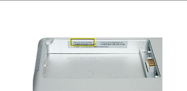
Serial Number Location
The serial number is located in the battery bay.
General Information |
PowerBook G4 (15-inch 1.67/1.5GHz) Take Apart - 5 |
Foot
Tools
This procedure requires the following tools:
•Foot kit
•Tweezers or needlenose pliers
•Soft cloth
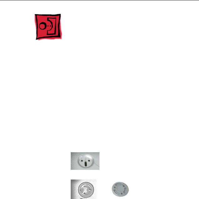
Preliminary Step
Before you begin, check the foot location that needs replacement and verify that the case plug is attached. Also verify that the case plug, and the case foot in the kit, match the pictures below.
Plug Area on Bottom Case |
Matching Foot |
Action |
|||||
|
|
|
|
|
|
|
|
Missing case plug |
Not available for |
Replace the bottom |
|||||
|
|
|
|
replacement |
case, or send to Apple |
||
|
|
|
|
|
|
|
Repair Center. |
|
|
|
|
|
|
|
|
|
|
|
|
|
|
|
|
Case plug |
Case foot |
Continue with the |
|||||
|
|
|
|
|
|
|
procedure, matching |
|
|
|
|
|
|
|
|
|
|
|
|
|
|
|
the foot to the plug on |
|
|
|
|
|
|
|
the bottom case. |
|
|
|
|
|
|
|
|
|
|
|
|
|
|
|
|
6 - PowerBook G4 (15-inch 1.67/1.5GHz) Take Apart |
Foot |
Procedure
Warning: The glue used in this procedure can bond instantly to skin. Do not touch the glue. In the event of contact, review the safety instructions at the end of this document. For additional information, refer to the glue manufacturer:
Elmer's Products, Inc.
Columbus, OH. 43215-3799
www.krazyglue.com
1.Place the computer upside down on a clean, lint-free cloth or other nonabrasive surface.
2.Select a foot from the kit. Verify that the case plug and case foot match (refer to the images shown in the table). Do not use a foot that does not match.
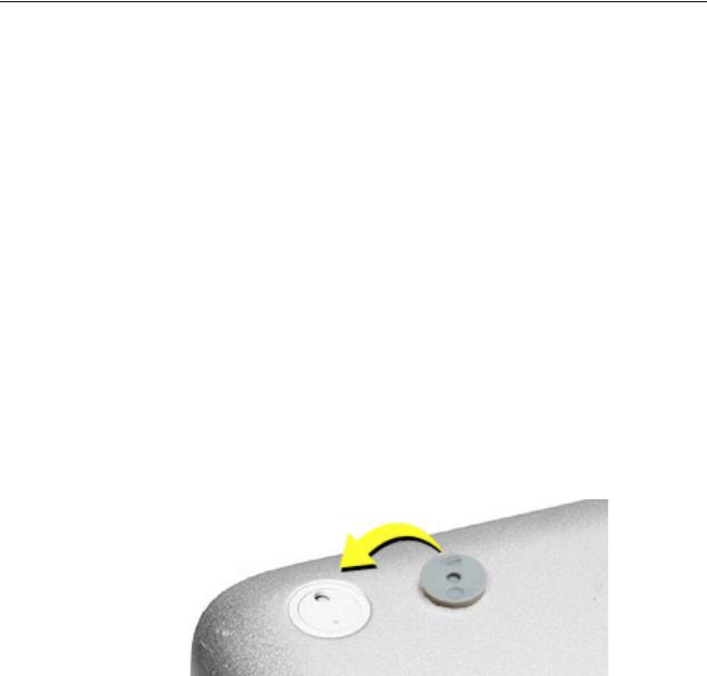
3.Make sure the plug area on the bottom case is clean. If any portion of the soft rubber foot remains, remove it so that only the hard plastic plug is visible.
Important: When positioning the foot, make sure the indents and bumps of the rubber foot match up and fit into the corresponding indents and bumps in the plug. This ensures a balanced and level fitting. (Note: The picture below is of a different foot than on the computer, and is for illustration only.)
Foot |
PowerBook G4 (15-inch 1.67/1.5GHz) Take Apart - 7 |

4.Warning: GLUE IS AN EYE AND SKIN IRRITANT. BONDS SKIN INSTANTLY. Do not touch the glue at any time. Before opening the glue, review the safety instructions at the end of this document.
Important: The glue tube included in the kit is sealed until first use. Do not break the seal until you are ready to use the glue. To break the seal, hold the tube upright and away from you. Place the hollow nozzle cap on the tube and tighten it all the way down. The tube is then ready to dispense the glue through the nozzle cap.
5.Apply one drop of glue to the plug on the bottom case. Do not spread the glue.
6.Using tweezers or needlenose pliers, carefully position the new foot so its textured surface fits into the inner ring of the plug.
7.Using the end of the tweezers or pliers—not your finger—lightly press and hold the foot in place for 30 seconds.
8.Before turning over the computer, allow the glue to set for at least 15 minutes.
9.Discard the tube of glue.
SAFETY INSTRUCTIONS: GLUE IS AN EYE AND SKIN IRRITANT. BONDS SKIN INSTANTLY. Contains ethyl cyanoacrylate. Avoid contact with skin and eyes. If eye or mouth contact occurs, hold eyelid or mouth open and rinse thoroughly but gently with water only for 15 minutes and GET MEDICAL ATTENTION. Liquid glue will sting eye temporarily. Solidified glue may irritate eye like a grain of sand and should be treated by an eye doctor. If skin bonding occurs, soak in acetone-based nail polish remover or warm soapy water and carefully peel or roll skin apart (do not pull). Contact through clothing may cause skin burn. If spilled on clothing, flush with cold water. Avoid prolonged breathing of vapors. Use with adequate ventilation. KEEP OUT OF REACH OF CHILDREN.
8 - PowerBook G4 (15-inch 1.67/1.5GHz) Take Apart |
Foot |
Battery
Tools
This procedure requires the following tools:
•Soft cloth
•Coin
Part Location
Preliminary Steps
Warning: Always shut down the computer before opening it to avoid damaging its internal components or causing injury. After you shut down the computer, the internal components can be very hot. Let the computer cool down before continuing.
Battery |
PowerBook G4 (15-inch 1.67/1.5GHz) Take Apart - 9 |
Procedure
Warning: If the computer has been recently operating, allow it to cool down before performing this procedure.
1.Shut down the computer.
2.Disconnect the power cord and any other cables connected to the computer.
3.Place the computer face down on a soft cloth.
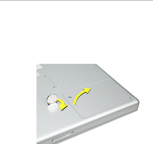
4.Insert a coin in the battery lock slot and turn it one quarter turn clockwise. The battery should raise up slightly. Lift the battery out of the battery bay.
10 - PowerBook G4 (15-inch 1.67/1.5GHz) Take Apart |
Battery |
Memory Door and
Memory Cards
Tools
This procedure requires the following tools:
•Soft cloth
•#0 Phillips screwdriver
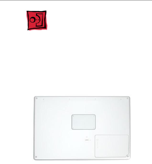
Part Location
Preliminary Steps
Before you begin, remove the battery.
Memory Door and Memory Cards |
PowerBook G4 (15-inch 1.67/1.5GHz) Take Apart - 11 |
Procedure
Warning: If the computer has been recently operating, allow it to cool down before performing this procedure.
1.Place the computer face down on a soft cloth.
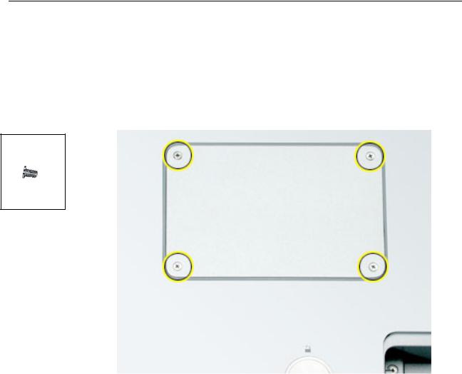
2.Remove the four screws from the memory door then remove the door.
922-6091
3.4 mm
Note: If only one memory card is installed, the factory installs it in the bottom memory slot.
Note: Memory must be removed from the top slot before removing from the bottom slot.
12 - PowerBook G4 (15-inch 1.67/1.5GHz) Take Apart |
Memory Door and Memory Cards |
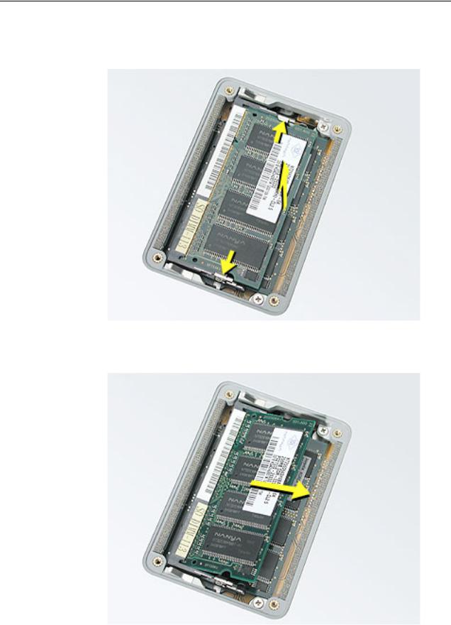
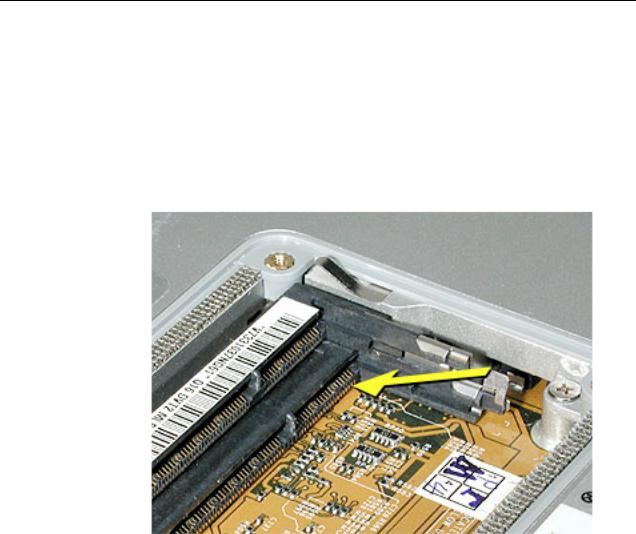
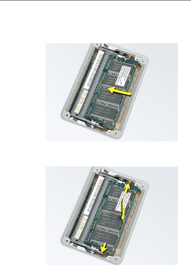
3.To remove memory cards, carefully spread the two locking tabs for the slot (top or bottom) away from the card on both sides and allow the card to pop up slightly.
4. Pull the card straight back and out of the memory slot.
Memory Door and Memory Cards |
PowerBook G4 (15-inch 1.67/1.5GHz) Take Apart - 13 |
Replacement Procedure
Notes:
•The top and bottom memory cards are inserted at different angles.
•If installing two cards, install into the bottom slot first.
•Align the notch in the memory card with the tooth in the slot before inserting.
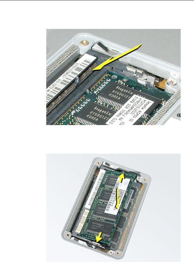
1.To install a memory card into the bottom slot, insert the card at a low angle behind the locking tabs of the top slot.
14 - PowerBook G4 (15-inch 1.67/1.5GHz) Take Apart |
Memory Door and Memory Cards |
2.Slide the card forward to the lower slot. Firmly push the card straight into the slot until it is fully and securely seated along its length.
Note: If the back of the card drops down before it is fully seated, raise it up enough to push it fully into the slot.
3.Carefully spread the two locking tabs for the bottom slot away from the card on both sides while pushing the card straight down until the tabs click onto both sides of the card, locking it into place.
Memory Door and Memory Cards |
PowerBook G4 (15-inch 1.67/1.5GHz) Take Apart - 15 |
4.If installing a memory card in the top slot, follow the same procedures as the bottom slot except insert the card at a 30-degree angle, above the locking tabs.
5.Push the card in until it is firmly seated.
6.As with the bottom slot, spread the locking tabs for the top slot while pushing the card straight down until it locks into place.
16 - PowerBook G4 (15-inch 1.67/1.5GHz) Take Apart |
Memory Door and Memory Cards |
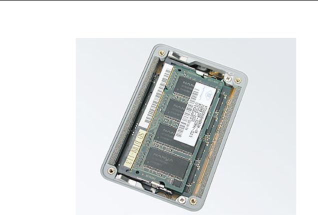
7. Cards should be flat and secure on both sides.
8.Install the memory door.
9.Replace the battery.
10.Use Apple System Profiler to verify that the memory is recognized. (Choose the menu bar Apple logo ( ) > About This Mac, click More Info..., select the System Profile tab, open the Memory Overview.)
Memory Door and Memory Cards |
PowerBook G4 (15-inch 1.67/1.5GHz) Take Apart - 17 |
Top Case
Tools
This procedure requires the following tools:
•#0 Phillips screwdriver (magnetized)
•1.5 mm Hex key (or Torx T6)
•Black stick (or other nonconductive nylon or plastic flat-blade tool)
•Soft cloth
•Multi-compartment screw tray
Part Location
18 - PowerBook G4 (15-inch 1.67/1.5GHz) Take Apart |
Top Case |
Preliminary Steps
Before you begin, remove the following:
•Battery
•Memory door
Procedure
Note: This procedure removes the top case and keyboard assembly. The keyboard is removable only after removing the top case.
1.Place the computer face down on a soft cloth.
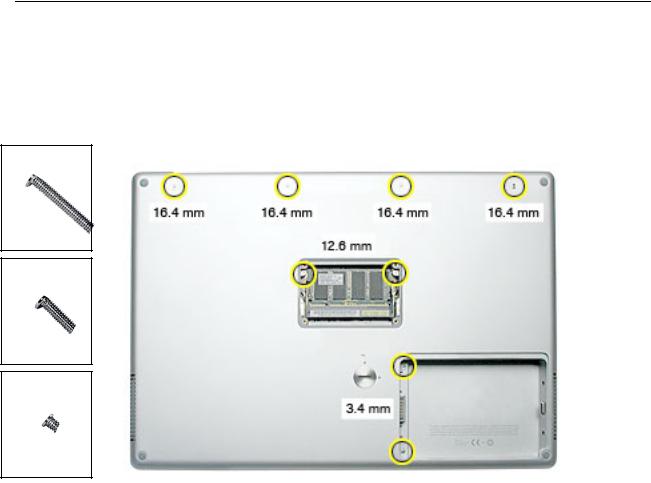
2.Remove the two screws inside the battery bay.
3.Remove the two screws from the memory bay.
4.Remove the four screws along the back edge.
922-6095
16
922-6719
12.6 mm
922-6091
3.4 mm
Top Case |
PowerBook G4 (15-inch 1.67/1.5GHz) Take Apart - 19 |
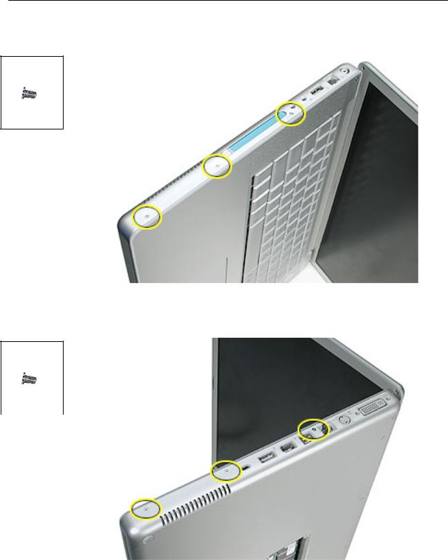
5. With the display open, rest the computer on one side. Remove the three screws.
922-6091
3.4 mm
6. Turn over the computer and remove the three screws on the other side.
922-6091
3.4 mm
20 - PowerBook G4 (15-inch 1.67/1.5GHz) Take Apart |
Top Case |
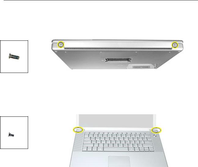
7.Open the computer slightly and rest it with the back facing up. Remove the two top screws along the back.
Note: Do not remove the bottom screws.
922-6100
5.3 mm
8.Lay the computer right side up and open the display slightly past 90-degrees.
9.Remove the two hex screws at the back corners of the top case (a Torx T6 can also be used).
922-6096
1.5mm Hex
4.4mm
Top Case |
PowerBook G4 (15-inch 1.67/1.5GHz) Take Apart - 21 |
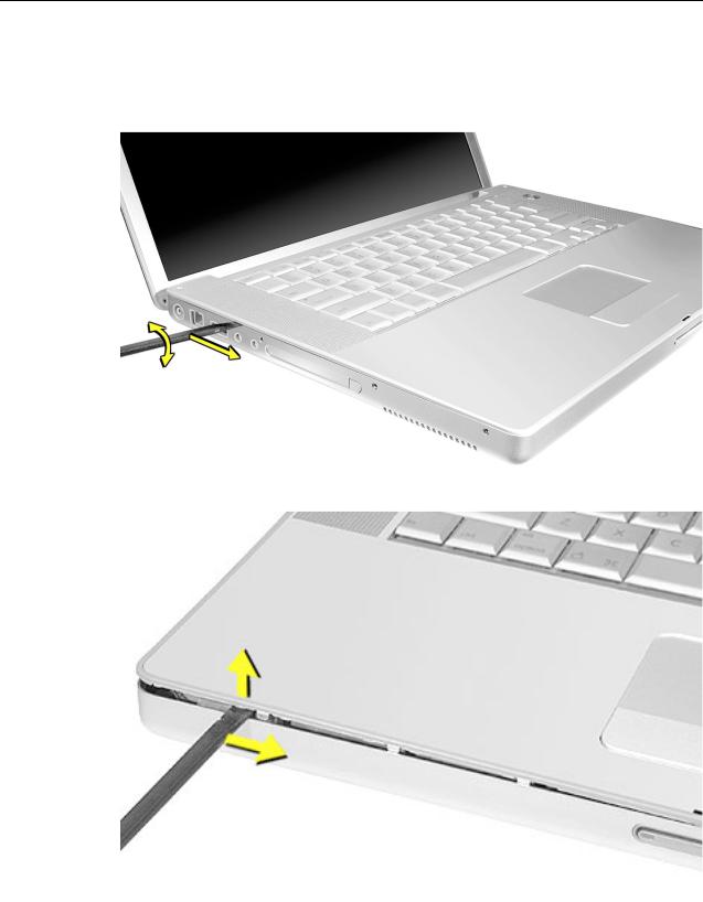
10.Along the left side, near the back, insert a black stick into the space between the top and bottom case. Work the black stick forward with a twisting motion until the black stick can be inserted on the left side of the front.
22 - PowerBook G4 (15-inch 1.67/1.5GHz) Take Apart |
Top Case |
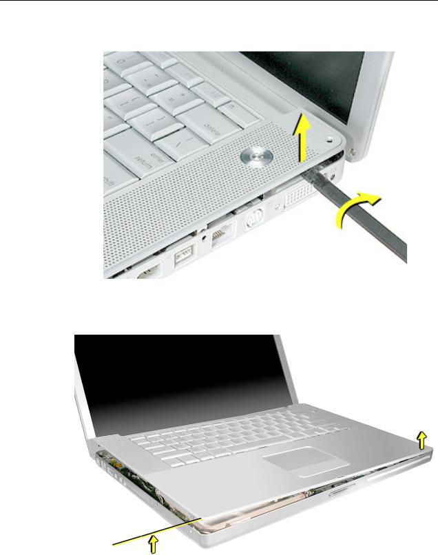
11. Loosen the back right side, if needed.
12.Work the left side up until the four catches over the optical drive slot release along the right side, then lift the top case straight up, slightly, to release it completely, but do not remove.
Top Case |
PowerBook G4 (15-inch 1.67/1.5GHz) Take Apart - 23 |
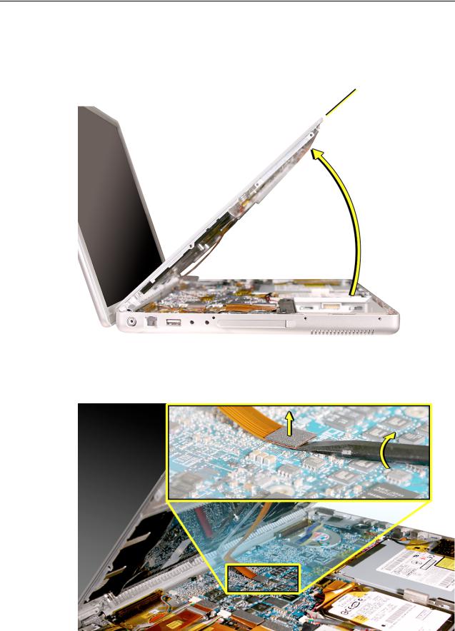
13.Lift the front of the top case and pivot along the back edge to about 45-degrees, to expose the keyboard flex cable connected to the logic board.
Important: Do not lift off the top case or strain the keyboard flex cable.
14.Remove any Kapton tape from the keyboard connector on the logic board, then use a black stick to disconnect the flex cable. Lift off the top case.
Replacement Note: When reinstalling, reapply Kapton tape where it was removed.
24 - PowerBook G4 (15-inch 1.67/1.5GHz) Take Apart |
Top Case |

Replacement Procedure
Note: If replacing the top case, remove the keyboard and transfer to the replacement top case.
1.Visually check to verify that all cables are connected and routed correctly with nothing raised up or incorrectly over a component.
2.Check perimeter wiring, where shown, to verify that it will not be caught or pinched by the top case during replacement.
3. Verify that the LVDS cable is secure and lays flat.
Top Case |
PowerBook G4 (15-inch 1.67/1.5GHz) Take Apart - 25 |
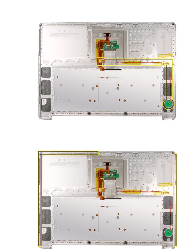
4. On the top case, check cable connections and routing.
5.Check that the perimeter metal tabs are not bent.
Note: The metal quickly fatigues and can break off easily. Be extremely careful to gently straighten tabs, if needed.
26 - PowerBook G4 (15-inch 1.67/1.5GHz) Take Apart |
Top Case |
6.Connect the flex cable from the top case to the logic board.
7.Lift the top case slightly and rotate it down over the bottom case (verify that the cable is folding properly) and align the corners.
8.Start at the right corner and guide the top case onto the bottom case. Use a black stick to carefully pull or push tabs slightly, if needed.
Important Notes:
•Some side screws have a flexible screw boss. If they block a tab on the top case from seating, use the pointed end of a black stick through the screw hole to push on the boss slightly.
•The tabs are fragile. Do not apply too much pressure or bend them.
•The top case should lay flat along the sides and top, if not, make sure that cables and components are not interfering.
•Screw order is vital for the proper attachment of the top case.
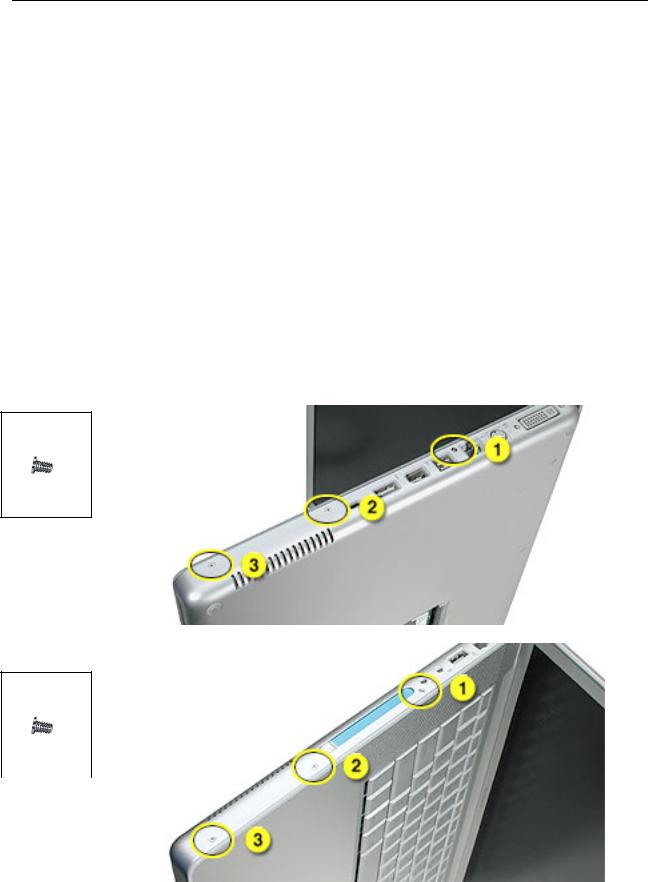
9.Reinstall the side screws in the order shown, below.
Replacement Note: Do NOT insert side screws into the DVI port screw holes. The screws can jam in the holes, requiring removing the logic board to remove.
922-6091
3.4 mm
922-6091
3.4 mm
Top Case |
PowerBook G4 (15-inch 1.67/1.5GHz) Take Apart - 27 |
922-6095
16
922-6719
12.6 mm
922-6091
3.4 mm
10.Close the computer, flip it over, and install the four back screws.
11.Install the two screws in the memory bay.
12.Install the memory door and four screws.
13.Install the two screw in the battery bay.
14.Replace the battery.
15.Testing the computer should include powering on, checking the keyboard and trackpad function.
Operate the computer in a darkened room to check for keyboard backlight function.
28 - PowerBook G4 (15-inch 1.67/1.5GHz) Take Apart |
Top Case |
Loading...