


 Loading...
Service Source
Power Mac G5
Updated: 16 September 2003
© 2003 Apple Computer, Inc. All rights reserved.

Power Mac G5 |
Power Mac G4 - 1 |

Service Source
Basics
Power Mac G5
© 2003 Apple Computer, Inc. All rights reserved.
Overview
Power Mac G5 is a 64-bit desktop computer powered by the PowerPC G5 processor. It offers memory expansion up to 8GB,1 GHz front-side bus, and advanced 64-bit computation, while running existing 32-bit applications natively. The computer also includes serial ATA hard drives, high-end graphics capabilities, and computer-controlled cooling based on four independent zones. Standard configurations are listed below.
1.6 GHz Uni |
1.8 GHz Uni |
2 GHz Dual |
|
|
|
800 MHz frontside bus |
900 MHz frontside bus |
1 GHz frontside bus |
|
|
|
256 MB DDR333 SDRAM, |
512 MB DDR400 SDRAM, |
512 MB DDR400 SDRAM, |
expandable to 4 GB |
expandable to 8 GB |
expandable to 8 GB |
|
|
|
80 GB Serial ATA drive |
160 GB Serial ATA drive |
160 GB Serial ATA drive |
|
|
|
SuperDrive |
SuperDrive |
SuperDrive |
|
|
|
Three PCI slots |
Three PCI-X slots |
Three PCI-X slots |
|
|
|
NVIDIA GeForce FX 5200 |
NVIDIA GeForce FX 5200 |
ATI Radeon 9600 Pro |
Ultra video card |
Ultra video card |
video card |
|
|
|
56K internal modem |
56K internal modem |
56K internal modem |
|
|
|
Overview |
Power Mac G5 Basics - 1 |
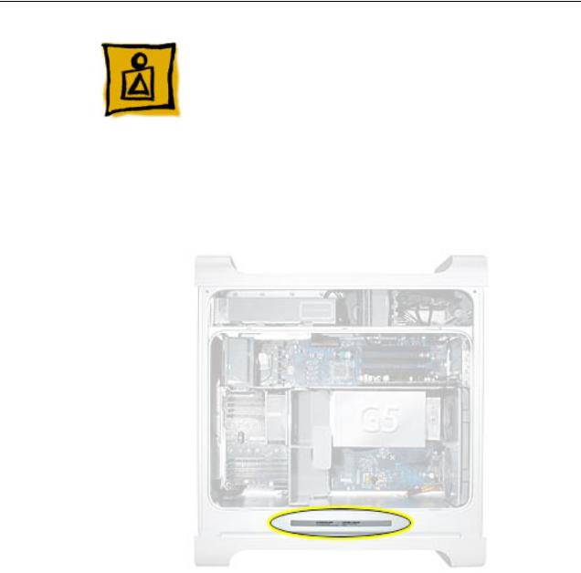
Serial Number Location
To identify a particular model of Power Mac G5, check the computer’s serial number, which lists the model’s configuration. The serial number is located directly below the air deflector inside the side access panel.
2 - Power Mac G5 Basics |
Serial Number Location |

What’s New
Overview
PowerPC G5— The Power Mac G5 computer incudes the new 64-bit PowerPC G5 processor running at either 1.6, 1.8, or 2.0 GHz, well beyond the speeds of G4 processors.
Serial ATA hard drives — Unlike older parallel drives, the new serial ATA drives in the Power Mac G5 offer up to 150 MB/s data throughput. The 7200 rpm drives come in 80, 160, or 250 GB capacity.
PCI-X slots—Higher-bandwidth PCI slots allow for greater amounts of data when using expansion cards that demand high performance. Both 100 and 133 MHz PCI-X slots are included in higher-end Power Mac G5 computers. For more information, see the “AGP/PCI Card” topic in the Take Apart chapter.
8x AGP bus— This bus provides a higher amount of data transfer to and from the graphics card. Both NVIDIA and ATI graphics cards are offered for the Power Mac G5.
USB 2.0 —All USB ports on the Power Mac G5 support the USB 2.0 standard, which accommodates more high speed peripherals.
Digital audio in and out —The Power Mac G5 introduces two new optical audio (S/PDIF) ports, allowing for optical audio input and output. These ports are in addition to the existing analog sound input and output ports.
Cooling zones — Nine case fans and blowers are logically grouped into four separate cooling zones in the Power Mac G5. Each zone is software-controlled by the system to only cool when necessary, making for a more efficient (and quieter) cooling solution.
Controller chips— The Power Mac G5 includes Northbridge and Southbridge controller chips that use “hyper-transport” technology. This new technology allows chips to talk to each other much faster than older Macs. The overall bandwidth of the system is also greatly improved.
ATA/100 bus for optical drives— This technology allows optical storage to read/write data much faster.
Interleaved DDR RAM—The Power Mac G5 requires pairs of DIMMs, which increases performance. Different models require either DDR 333 or DDR 400 RAM. DIMMs must be installed in pairs of equal size and kind. For more information, see the “Memory (DIMMs)” topic in the Take Apart chapter.
What’s New |
Power Mac G5 Basics - 3 |
DDR Memory
Depending on the model, Power Mac G5 computers have either four or eight Dual Inline Memory Module (DIMM) slots for Double-Data-Rate (DDR) Synchronous Dynamic Random-Access Memory (SDRAM) devices. The computers ship with a minimum of 256 MB of RAM, installed as a pair of 128 MB DIMMs in two of the DIMM slots. You can install additional DIMMs, provided they are installed in pairs of equal size. A diagram marked on the logic board near the slots illustrates how the pairs must be installed.
To determine the types of DIMMs to install, refer to the table below:
DIMM Slots |
DIMM speed |
Maximum amount |
4 (two banks of 2 slots) |
333 MHz, PC 2700 |
up to 4 GB |
8 (two banks of 4 slots) |
400 MHz, PC 3200 |
up to 8 GB |
In addition, DIMMs must fit these specifications:
•2.5 volt
•84-pin module
•Maximum number of memory devices on DDR SDRAM:16
•Nonparity
•No error correcting codes (ECC)
•Unbuffered (registered or buffered DDR SDRAM cannot be used)
4 - Power Mac G5 Basics |
What’s New |

Video
The Power Mac G5 computer comes with a graphics card installed in the AGP 3.0- compliant 8x Pro slot.
All graphics cards support dual displays in either extended desktop or video mirroring mode, and support digital resolutions up to 1920x1200 pixels and analog resolutions up to 1600x1200 pixels.
The display memory on the AGP card is separate from the main memory. The display memory consists of 64 or 128 MB of DDR devices configured to make a 128-bit data bus. The display memory cannot be expanded by the user.
The supported graphics cards are shown below:
Graphics |
Video SDRAM |
Connectors |
NVIDIA GeForce FX 5200 Ultra |
64 MB DDR |
ADC and DVI-I |
ATI Radeon 9600 Pro |
64 MB DDR |
ADC and DVI-I |
ATI Radeon 9800 Pro (CTO) |
128 MB DDR |
ADC and DVI-I |
Fan Controller
The Power Mac G5 system employs advanced thermal management to keep acoustic noise to a minimum. The system is divided into discrete zones, each with independently controlled fans bringing in cool air from the front of the enclosure, directing it through ducts and exhausting it out the rear. Temperature and power consumption are monitored by the operating system, which communicates with the Fan Control Unit, which in turn controls and monitors fan operation. Note that if Mac OS X is not booted, thermal management will not work correctly.
Important: To ensure proper fan and temperature control, you must run Apple Service Diagnostic whenever you replace a processor or logic board with a new processor or logic board. You must also run the diagnostic if you re-install the same processor but in a different connector from the one in which it was originally installed. For more information, see “Thermal Calibration” in the Troubleshooting chapter.
Optical Audio
Digital data is transmitted to and from the optical audio I/O using special optical cables. The 7.5 mm digital optical connectors on the cables, commonly referred to as TOSLink, are for both input and output and conform to the IEC60874-17 connector standard.
The TOSLink friction-lock type F-05 connectors are available from pro-audio, musician’s supply, hi-fi, and other retailers.
What’s New |
Power Mac G5 Basics - 5 |

Analog audio signals are converted to digital data internally. All audio is handled digitally inside the computer, including audio data from the CD or DVD drive and from devices connected to the USB and FireWire ports. Audio data is converted to analog form for output to the internal speaker, the headphones, or the analog output port.
Wireless
The Power Mac G5 supports an optional internal Apple Bluetooth module that enables short-range wireless connections between desktop and laptop computers and a host of other peripheral devices. Bluetooth support is built into Mac OS X and compliant with Bluetooth specification v1.1. It operates on a globally available 2.4 GHz frequency band (ISM band) for worldwide compatibility and has a maximum throughput of 1Mbps.
The Bluetooth technology supports the following profiles:
•synchronization —enables synchronization of devices over Bluetooth
•serial —provides a wireless serial connection to other Bluetooth devices
•dial-up networking (DUN) — enables a mobile phone to act as a modem
•object push —enables the transfer of files between Bluetooth devices
Important: For proper range and operation, the external Bluetooth antenna must be attached to the Bluetooth port and the external AirPort antenna must be attached to the AirPort port on the back panel of the Power Mac G5.
Ports
The following ports are included on the front and back panels of the Power Mac G5. For illustrations of the port locations, see the “External Views” topic in the Views chapter.
Front
•Power button
•Headphone port
•USB 2.0 port
•FireWire 400 port
Rear
•AirPort antenna port
•Bluetooth antenna port
•Optical audio-out port
•Optical audio-in port
•Audio line-out port
•Audio line-in port
•USB 2.0 ports (two ports)
•FireWire 400 port
•FireWire 800 port
•10/100/1000Base-T Ethernet port
•Modem port
6 - Power Mac G5 Basics |
What’s New |

What’s New |
Power Mac G5 Basics - 7 |
Service Source
Take Apart
Power Mac G5
© 2003 Apple Computer, Inc. All rights reserved.

General Information
Orientation
For most take-apart procedures, it is recommended that you lay the computer on its side before removing or installing the part. For proper operation, however, Apple recommends that the unit be run in the upright position. The computer should never be operated on its side with the access panel facing down.
Tools
The following tools are required to service the computer:
•Long-handled magnetic Phillips screwdriver (10-inch shaft)
•Short-handled magnetic Phillips screwdriver
•Flatblade screwdriver
•Jeweler’s flatblade screwdriver
•Needlenose pliers
•Long-handled hex wrench
•Tape (for temporarily holding cables out of the way)
•Small mirror (for seeing small boards inside the enclosure)
•Soft cloth (for protect removed parts from scratches)
General Information |
Power Mac G5 Take Apart - 1 |

Opening the Computer
Tools
No tools are required for this procedure.
Preliminary Steps
1.Shut down the computer.
Warning: Always shut down the computer before opening it to avoid damaging its internal components or the components you are installing. Do not open the computer or attempt to install items inside it while it is on.
2.Wait 5 to 10 minutes to allow the computer’s internal components to cool.
Warning: After you shut down the system, the internal components can be very hot. You must let the computer cool down before continuing.
3.Unplug all external cables from the computer except the power cord.
4.Touch the metal PCI access covers on the back of the computer to discharge any static electricity from your body.
Important: Always discharge static before you touch any parts or install any components inside the computer. To avoid generating static electricity, do not walk around the room until you have finished working and closed the computer.
5.Unplug the power cord.
6.Put on an ESD wrist strap.
2 - Power Mac G5 Take Apart |
Opening the Computer |

Procedure
1. Hold the side access panel and lift the latch on the back of the computer.
Warning: The edges of the access panel and the enclosure can be sharp. Be very careful when handling them.
2. Remove the access panel and place it on a flat surface covered by a soft, clean cloth.
Replacement Note: Make sure the latch is in the up position before replacing the access panel. If the latch is down, the access panel will not seat correctly in the enclosure.
Opening the Computer |
Power Mac G5 Take Apart - 3 |
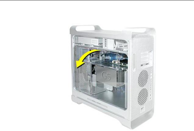
3. Remove the air deflector and place it on a soft, clean cloth.
Replacement Note: To replace the air deflector, insert the three tabs on the bottom edge of the deflector into the three slots in the bottom frame of the enclosure. Then swing the deflector up flush against the top frame of the enclosure.
Important: Make sure you re-install the air deflector before replacing the access panel. If the air deflector is not installed, the computer will not function properly.
4 - Power Mac G5 Take Apart |
Opening the Computer |
Serial ATA Hard Drive
The Power Mac G5 computer can accommodate two serial ATA hard drives in its internal hard drive bay. In most configurations, a single hard drive occupies the top portion of the bay. You can install one additional serial ATA hard drive to the empty slot in the bay.
Important: Use the original Apple cables that came with the Power Mac G5 when installing ATA hard drives.
Tools
The only tool required for this procedure is a Phillips screwdriver.
Preliminary Steps
Before you begin, open the computer.
Part Location
Serial ATA Hard Drive |
Power Mac G5 Take Apart - 5 |
Procedure
1.Release the drive locking latch by rotating it up.
2.Disconnect the drive data cable and power cable from the hard drive.
3. Pull the drive out of the drive bay, being careful not to touch the bottom of the drive.
Important: If the printed circuit board (PCB) is exposed on the bottom of the hard drive, hold the drive by its sides. To avoid damaging the replacement drive, take care not to touch the PCB during installation.
6 - Power Mac G5 Take Apart |
Serial ATA Hard Drive |

4.If you are replacing the drive with a new drive, transfer the four hard drive guide screws from the sides of the original drive to the replacement drive.
5.If you are installing an additional drive, remove the four guide screws from the left side of the hard drive bay and screw them into the sides of the new drive.
Serial ATA Hard Drive |
Power Mac G5 Take Apart - 7 |
Replacement Note: When replacing the top drive, make sure the guide screws align with the middle slot of the drive bay, and then gently push the drive into the bay until it snaps into place in the top position.
When installing a bottom drive, align the guide screws with the bottom slot of the drive bay and slide the drive in until it snaps into place.
8 - Power Mac G5 Take Apart |
Serial ATA Hard Drive |

Optical Drive
Important: When installing a replacement optical drive, use the original Apple cables that came with the Power Mac G5.
Tools
No tools are required for this procedure.
Preliminary Steps
Before you begin, open the computer.
Part Location
Optical Drive |
Power Mac G5 Take Apart - 9 |
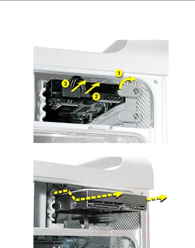
Procedure
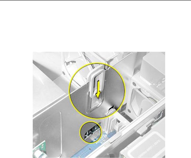
1.Disconnect the optical drive ribbon cable from the logic board. (The cable connector is located under the media shelf that holds the optical drive.)
2. Push the optical drive levers out to release the drive.
10 - Power Mac G5 Take Apart |
Optical Drive |

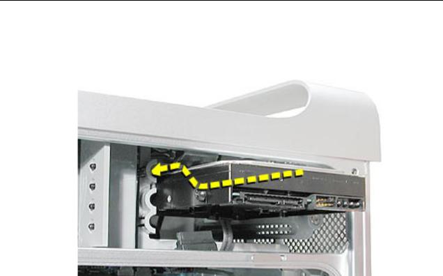
3.Place the fingers on one hand inside the opening for the optical drive cable and push the edge of the drive forward. The drive will move part way out of the media shelf.
4. Disconnect the power cable from the drive.
5.Route the drive ribbon cable out through the opening in the media shelf and remove the drive and ribbon cable from the computer.
Optical Drive |
Power Mac G5 Take Apart - 11 |
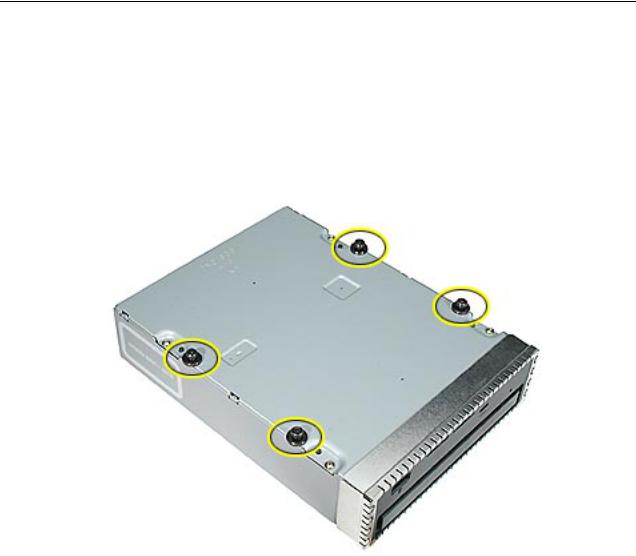
6.If you are replacing the drive with a new drive, install the standoffs on the bottom of the new drive.
Note for SuperDrives: Two bags of standoffs are included with each drive. Use the standoffs from the bag marked with the same manufacturer’s name as printed on the drive.
Note for Combo Drives: Transfer the standoffs from the original drive to the replacement drive.
12 - Power Mac G5 Take Apart |
Optical Drive |
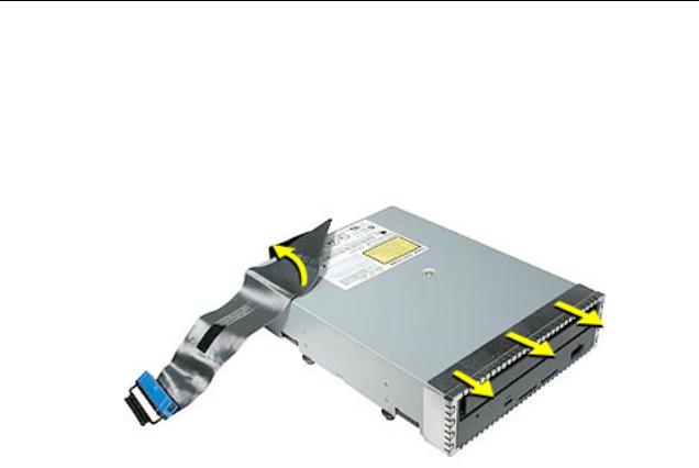
7.Disconnect the ribbon cable from the back of the drive, and then carefully pry the cable from the top of the drive. Transfer the cable to the top of the replacement drive, and connect the cable to the drive.
Note: Reusable adhesive tape on the underside of the cable attaches the cable to the drive. When removing the cable from the original drive, be careful to keep the tape with the cable.
8.Carefully remove the EMI shield from the front of the original drive and transfer it to the front of the replacement drive.
Replacement Note: Insert the optical drive part way into the optical drive bay, and connect the power cable to the drive. Then bend down the free end of the ribbon cable, route it through the opening at the back of the media shelf, and connect the cable to the logic board.
Optical Drive |
Power Mac G5 Take Apart - 13 |
Front Inlet Fan(s)
The front inlet fan assembly consists of one or two fans in a plastic bracket. If the computer is a uniprocessor, the assembly contains a single fan; if the computer is a dual processor, the assembly contains two fans connected by a single cable.
You must remove the front inlet fan assembly to access many other parts within the computer. For this access, remove the bracket with the fans attached. You will have to remove the fans from the bracket only if you are replacing the fans themselves.
Tools
The only tool required for this procedure is needlenose pliers.
Preliminary Steps
Before you begin, open the computer and lay it on its side with the access side facing up.
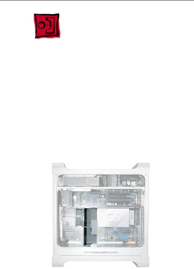
Part Location
14 - Power Mac G5 Take Apart |
Front Inlet Fan(s) |
Procedure
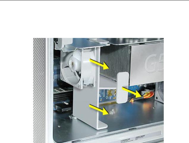
1.Hold the front inlet fan assembly by the front handle and firmly pull it out of the computer.
Front Inlet Fan(s) |
Power Mac G5 Take Apart - 15 |
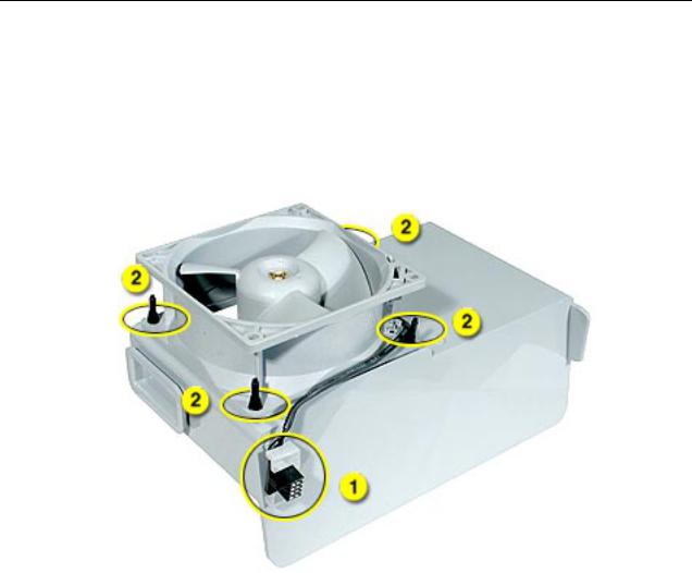
2.If you are replacing the fan(s) in the bracket, do the following:
•Remove the fan cable from the cable guide.
•Using needlenose pliers, pull the fan(s) off the grommet fasteners, and remove the fan(s) and cable from the bracket.
Important: If you are replacing two fans, be careful that you do not separate the fans from each other. They are connected by a common cable.
16 - Power Mac G5 Take Apart |
Front Inlet Fan(s) |
Replacement Note: To replace the front inlet fan bracket in the enclosure, align the large rail on the bracket with the cutout in the PCI divider and press firmly.
Important: Make sure the connector on the fan fully engages the fan connector on the logic board, or the computer will not operate properly. Gently pull the fan assembly to test whether it is connected.
Front Inlet Fan(s) |
Power Mac G5 Take Apart - 17 |

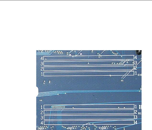
Memory (DIMMs)
Depending on the model, Power Mac G5 computers have either four or eight Dual Inline Memory Module (DIMM) slots arranged in two banks. The slots accept Double-Data-Rate (DDR) Synchronous Dynamic Random-Access Memory (SDRAM) devices.
The computers ship with a minimum of 256 MB of RAM, provided by a pair of 128 MB DIMMs installed in slot 1 of each DIMM bank. You can add DIMMs, provided they are installed in pairs of equal size, one per bank, from the center outward. A diagram marked on the logic board near the DIMM slots illustrates how the pairs must be installed.
To determine the types of DIMMs to install, refer to the table below:
DIMM Slots |
DIMM speed |
Maximum amount |
4 |
333 MHz, PC 2700 |
up to 4 GB |
8 |
400 MHz, PC 3200 |
up to 8 GB |
18 - Power Mac G5 Take Apart |
Memory (DIMMs) |
In addition, DIMMs must fit these specifications:
•2.5 volt
•84-pin module
•Maximum number of memory devices on DDR SDRAM:16.
•Nonparity
•No error correcting codes (ECC)
•Unbuffered (registered or buffered DDR SDRAM cannot be used)
Important: Always install DIMMs in pairs of equal size. Memory from older Macintosh computers is not compatible with the Power Mac G5. Do not use older memory, even if it fits into the DIMM slots.
Tools
No tools are required for this procedure.
Preliminary Steps
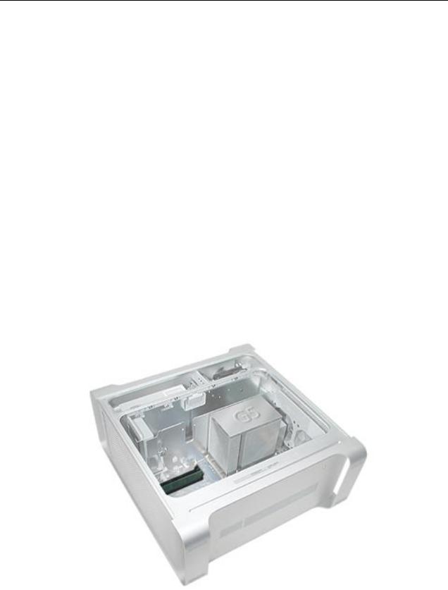
Before you begin, open the computer, lay it on its side with the access side facing up, and remove the front inlet fan assembly.
Part Location
Memory (DIMMs) |
Power Mac G5 Take Apart - 19 |
Loading...