


 Loading...
Service Source
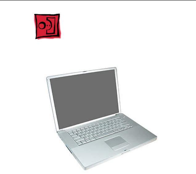
PowerBook G4 (15-inch FW 800) PowerBook G4 (15-inch 1.5/1.33GHz)
Updated 12 November 2004
© 2004 Apple Computer, Inc. All rights reserved.
Service Source
Adjustments
PowerBook G4 (15-inch FW 800) PowerBook G4 (15-inch 1.5/1.33GHz)
© 2004 Apple Computer, Inc. All rights reserved.

Latch Adjustment
Overview
If the display latch does not secure the display to the top case, or releases before the latch button is pushed, an adjustment to the latch hook can be made to correct this. Alternately, the computer can be sent to the Apple Repair Center for service.
The display latch consists of a latch mechanism under the top case (it’s actually attached to the bottom case frame) and a pivoting latch hook within the display assembly. The hook is pulled down into the latch mechanism by a magnet as it approaches the top case, and is secured under an overhang on the latch mechanism.
Tools
This procedure requires the following tools:
•Black stick (or other non-marring nylon or plastic pointed tool)
•Magnet
Preliminary Steps
Warning: While performing the following procedures, notice the hook as it is pulled out of the display housing and into the slot in the top case. If an adjustment to the latch hook is performed later, the hook must be adjusted only very slightly, to stay within the slot on the top case.
Before performing the latch adjustment, test the current operation of the latch:
1.Push the display down to about two inches from the top case. Then push the display very slowly until it just touches the top case, and immediately release.
If working properly, the latch should secure the display to the top case through the following tests:
•Pound on the table top, left and right of the computer.
•Pull up on the sides of the display.
Repeat the above procedures several times to verify the operation of the latch.
2.Whether or not the latch functioned properly, use the following procedures to achieve or verify proper latching function.
Latch Adjustment |
PowerBook G4 (15-inch FW 800_1.5/1.33GHz) Adjustments - 1 |
Procedure
Note: The latch mechanism under the top case of the computer has a small amount of right and left play (less than 1 mm), and can shift during normal operation.
The following procedures will test the latching function with the latch mechanism at its maximum right and left positions, and the latch hook will be very slightly bent, as necessary.
Important: The latch hook metal can become brittle and break if it is bent too much, especially if it is over-bent and bent back. Work carefully and with restraint to avoid over bending the latch hook. If the latch hook breaks, the entire display panel assembly will need to be replaced.
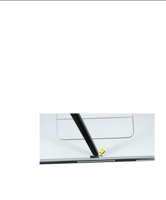
1.Open the display and use a black stick to push the latch mechanism, at the location shown, to move it to the right as far as it will go (less than 1 mm).
Note: You may not notice movement if the latch mechanism was already in this position.
Note: In this position, the latch mechanism has the least overhang available to catch the latch hook, so this would be the “worst-case” position.
2.Perform the testing procedures in step 1 of the Preliminary Steps, above.
3.If the latch functions properly, skip to step 7, but refer back to the procedures below, if the latch hook requires an adjustment.
2 - PowerBook G4 (15-inch FW 800_1.5/1.33GHz) Adjustments |
Latch Adjustment |

4.If the latch does not function properly, adjust the latch hook as follows:
Open the display to a 90-degree angle and use a magnet to pull out the latch hook and tightly grasp it between your thumb and forefinger as close to the display as possible, as shown.
5.Carefully exert a very slight controlled downward pressure on the latch hook.
Important: Do not push only with your thumb. Hold the latch hook tightly between your thumb and forefinger to support the latch hook and prevent too much bending force.
Latch Adjustment |
PowerBook G4 (15-inch FW 800_1.5/1.33GHz) Adjustments - 3 |

6.Release the latch hook and perform the latch tests as before. Continue the above procedure until the latch functions properly.
7.Use a black stick to push on the latch mechanism, at the location shown, to move it to the left as far as it will go (about 1 mm).
Note: This is the ideal latch mechanism position and the mechanism will be left at this location.
When you push the latch mechanism correctly, you will notice the mechanism move, where shown below.
8.Repeat the previous latch closing tests, and latch hook adjustment if needed, until the latch works properly in this position.
4 - PowerBook G4 (15-inch FW 800_1.5/1.33GHz) Adjustments |
Latch Adjustment |

Display Rear Housing
Adjustment
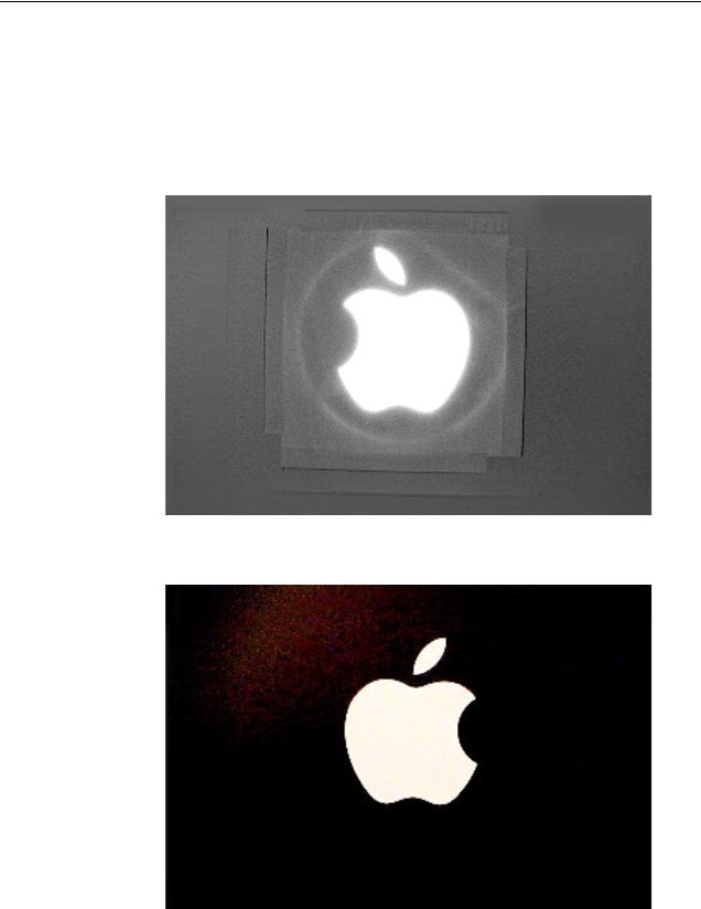
Overview
Earlier display rear housing parts include a shim set on each side of the logo diffuser on the inner side of the housing. New replacement display housing parts include a new softer diffuser and no shim set. When you are replacing an LCD panel in a display assembly, you must either replace the display housing with a new display housing, or remove the shim set and replace the diffuser on the existing display housing. Follow this procedure to modify an earlier display housing.
Tools
This procedure requires the following tools:
•LCD panel with new softer diffuser
•Black stick (or other non-marring nylon or plastic pointed tool)
•Cloth rag
•Solvent to remove adhesive (such as Goof-Off goo remover)
•Fine-point permanent marking pen with black ink
•Compressed air
•Logo diffuser 922-6342 (included with replacement LCD panels)
Display Rear Housing Adjustment |
PowerBook G4 (15-inch FW 800_1.5/1.33GHz) Adjustments - 5 |

Preliminary Step
Before performing the display rear housing adjustment, check the current housing. If it appears as shown below (with a set of shims on both sides of the logo diffuser), continue with the procedure.
6 - PowerBook G4 (15-inch FW 800_1.5/1.33GHz) Adjustments |
Display Rear Housing Adjustment |
Procedure
Important: The logo diffuser protects the Apple logo on the back of the housing. To protect the logo from damage, do not remove the diffuser until after the sets of shims have been removed.
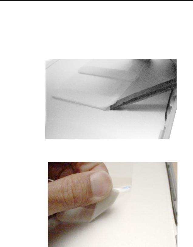
1. Using a black stick, start to loosen the two sets of shims.
2. With one end loosened, peel up the sets of shims.
Display Rear Housing Adjustment |
PowerBook G4 (15-inch FW 800_1.5/1.33GHz) Adjustments - 7 |
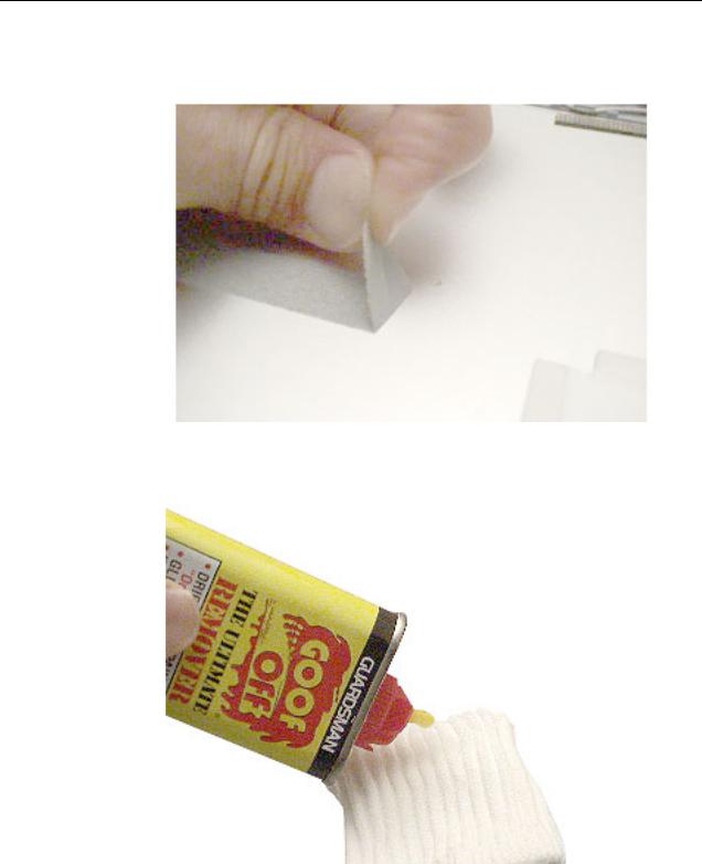
3.If part of the foam strip sticks to the housing, remove it with a black stick or your fingers.
4.If a patch of adhesive remains on the housing, use a small amount of solvent on a rag to clean off the area.
5. Rub the patch until the adhesive is gone and the housing is clean.
8 - PowerBook G4 (15-inch FW 800_1.5/1.33GHz) Adjustments |
Display Rear Housing Adjustment |
6.With the two sets of shims removed, the housing should appear as shown below with the square diffuser in the center of the display housing.
7.To prepare the housing for placement of the new diffuser, use a permanent marking pen along the four sides of the diffuser.
Display Rear Housing Adjustment |
PowerBook G4 (15-inch FW 800_1.5/1.33GHz) Adjustments - 9 |

8. Using a black stick, carefully pry up the diffuser foam at one corner, and pull it back.
9.Use the black stick to loosen all four sides of the diffuser. Be careful not to mar the logo.
10.Pull the diffuser off.
10 - PowerBook G4 (15-inch FW 800_1.5/1.33GHz) Adjustments |
Display Rear Housing Adjustment |

11. Important: Before applying the new diffuser, make sure nothing adheres to the clear plastic window. If necessary, use an air compressor to remove any dust or particles.
12. Check both sides of the replacement diffuser to make sure it is completely clean.
Display Rear Housing Adjustment |
PowerBook G4 (15-inch FW 800_1.5/1.33GHz) Adjustments - 11 |

13. Remove the backing on the foam strips.
14.Because the diffuser is square, you may orient it in any way as long as it aligns with the pen lines on the housing. Place it straight against one line, and allow the foam strips to adhere to the housing and match up to the other pen lines.
Important: To avoid creating pressure points on the LCD panel, the adhesive foam must not ride up onto the plastic of the logo at any point, even slightly. Check this by running your finger along the foam. If it goes over the logo plastic, reapply the diffuser.
12 - PowerBook G4 (15-inch FW 800_1.5/1.33GHz) Adjustments |
Display Rear Housing Adjustment |
15.With the diffuser secured on the housing, peel up the clear, protective film backing if it is installed. The backing will appear wrinkled if it is in place.
16.To make sure that the diffuser is installed correctly, hold the display housing up to a strong light and visually inspect the position of the foam strips to the clear plastic window. If you see an overlap, remove the diffuser and make sure a new one is installed correctly.
17.As a final check, turn over the housing and inspect the Apple logo for contamination. The logo should be uniformly white.
Display Rear Housing Adjustment |
PowerBook G4 (15-inch FW 800_1.5/1.33GHz) Adjustments - 13 |

Service Source
Take Apart
PowerBook G4 (15-inch FW 800) PowerBook G4 (15-inch 1.5/1.33GHz)
© 2004 Apple Computer, Inc. All rights reserved.
General Information
Overview
The main differences between the two computers covered in this manual are:
PowerBook G4 (15-inch FW800)
•1.0 and 1.25 GHz logic boards
•Standard modem
•ATI Mobility Radeon 9600 graphics chip
PowerBook G4 (15-inch 1.5/1.33GHz)
•1.33 and 1.5 GHz logic boards
•Apple internal 56K modem (April 2004)
•ATI Mobility Radeon 9700 graphics chip
•Thermal paste is used on the heatsink for the graphics chip mating surface
General Information |
PowerBook G4 (15-inch FW 800_1.5/1.33GHz) Take Apart - 1 |

Some key features common to both that distinguish these computers from earlier PowerBook models include:
•New aluminum alloy enclosure
•Built-in Bluetooth
•Built-in FireWire 800 port
•Supports USB 2.0
•Uses double-data rate (DDR) memory
•Optional AirPort Extreme card
•Optional fiber optic backlit keyboard with ambient light sensors
•New battery pack
New Procedures
If you are familiar with taking apart notebook computers, there are a few critical differences:
•Important: The top case removal has two critical removal steps:
–Clips behind the optical drive felt must be disengaged before the top case can be lifted off.
–There are two flex cables (keyboard and multifunction trackpad) from the top case to the logic board. Carefully lift the top case to avoid pulling these connectors off the main logic board.
•The keyboard is secured with screws accessible from under the top case.
•Memory cards are easily accessible from the bottom of the computer. Important: To avoid applying too much pressure onto the memory slot locking tabs, spread the tabs apart when installing memory cards.
•The AirPort Extreme card is easily installed or replaced through a door in the main battery compartment.
•The quantity and types of screws differ from earlier models.
Important Memory Note
Memory from the previous 15-inch (Titanium) PowerBook is not compatible with this computer.
Memory from the PowerBook G4 (15-inch FW800) is compatible, however, not all memory compatible with the PowerBook G4 (1.5/1.33GHz) will be compatible with the PowerBook G4 (15-inch FW800).
2 - PowerBook G4 (15-inch FW 800_1.5/1.33GHz) Take Apart |
General Information |

Tools
The following tools are recommended for the take apart procedures.
•ESD wrist strap and mat
•Soft cloth
•#0 Phillips screwdriver (magnetized)
•#1 Phillips screwdriver (magnetized)
•4 mm socket wrench
•5 mm socket wrench
•1.5 mm Hex key (or Torx T6)
•Needlenose pliers
•Torx T8 screwdriver
•Torx T6 screwdriver
•Thermal pad kit (076-1055)
•EMI gaskets kit (076-1057)
•Alcohol pads
•Black stick (nylon probe tool 922-5065) (or other nonconductive nylon or plastic flatblade tool)
•Multi-compartment screw tray (such as a plastic ice cube tray)
•Double-stick tape
•Kapton® tape (922-1731)
•Voltmeter (for troubleshooting)
•Small low-power magnet (for troubleshooting)
•Apple Pro keyboard and mouse (for troubleshooting)
General Information |
PowerBook G4 (15-inch FW 800_1.5/1.33GHz) Take Apart - 3 |
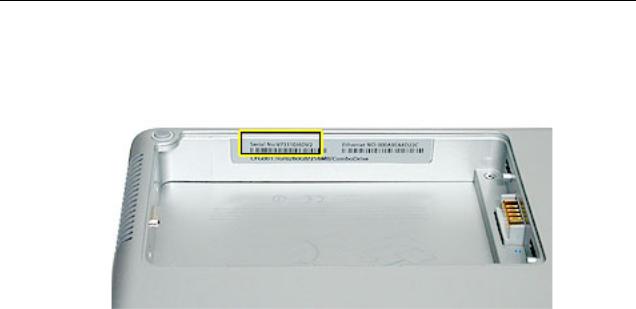
Serial Number Location
The serial number is located in the battery bay.
4 - PowerBook G4 (15-inch FW 800_1.5/1.33GHz) Take Apart |
General Information |
Foot
Tools
This procedure requires the following tools:
•Foot kit
•Tweezers or needlenose pliers
•Soft cloth
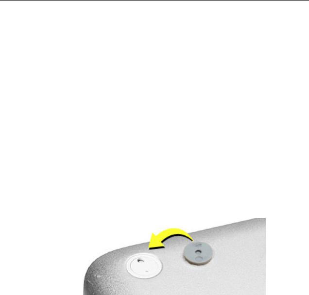
Preliminary Step
Before you begin, check the foot location that needs replacement and verify that the case plug is attached. Also verify that the case plug, and the case foot in the kit, match the pictures below.
Plug Area on Bottom Case |
Matching Foot |
Action |
|||||
|
|
|
|
|
|
|
|
Missing case plug |
Not available for |
Replace the bottom |
|||||
|
|
|
|
replacement |
case, or send to Apple |
||
|
|
|
|
|
|
|
Repair Center. |
|
|
|
|
|
|
|
|
|
|
|
|
|
|
|
|
Case plug |
Case foot |
Continue with the |
|||||
|
|
|
|
|
|
|
procedure, matching |
|
|
|
|
|
|
|
|
|
|
|
|
|
|
|
the foot to the plug on |
|
|
|
|
|
|
|
the bottom case. |
|
|
|
|
|
|
|
|
|
|
|
|
|
|
|
|
Foot |
PowerBook G4 (15-inch FW 800_1.5/1.33GHz) Take Apart - 5 |
Procedure
Warning: The glue used in this procedure can bond instantly to skin. Do not touch the glue. In the event of contact, review the safety instructions at the end of this document. For additional information, refer to the glue manufacturer:
Elmer's Products, Inc.
Columbus, OH. 43215-3799
www.krazyglue.com
1.Place the computer upside down on a clean, lint-free cloth or other nonabrasive surface.
2.Select a foot from the kit. Verify that the case plug and case foot match (refer to the images shown in the table). Do not use a foot that does not match.
3.Make sure the plug area on the bottom case is clean. If any portion of the soft rubber foot remains, remove it so that only the hard plastic plug is visible.
Important: When positioning the foot, make sure the indents and bumps of the rubber foot match up and fit into the corresponding indents and bumps in the plug. This ensures a balanced and level fitting. (Note: The picture below is of a different foot than on the computer, and is for illustration only.)
6 - PowerBook G4 (15-inch FW 800_1.5/1.33GHz) Take Apart |
Foot |

4.Warning: GLUE IS AN EYE AND SKIN IRRITANT. BONDS SKIN INSTANTLY. Do not touch the glue at any time. Before opening the glue, review the safety instructions at the end of this document.
Important: The glue tube included in the kit is sealed until first use. Do not break the seal until you are ready to use the glue. To break the seal, hold the tube upright and away from you. Place the hollow nozzle cap on the tube and tighten it all the way down. The tube is then ready to dispense the glue through the nozzle cap.
5.Apply one drop of glue to the plug on the bottom case. Do not spread the glue.
6.Using tweezers or needlenose pliers, carefully position the new foot so its textured surface fits into the inner ring of the plug.
7.Using the end of the tweezers or pliers—not your finger—lightly press and hold the foot in place for 30 seconds.
8.Before turning over the computer, allow the glue to set for at least 15 minutes.
9.Discard the tube of glue.
SAFETY INSTRUCTIONS: GLUE IS AN EYE AND SKIN IRRITANT. BONDS SKIN INSTANTLY. Contains ethyl cyanoacrylate. Avoid contact with skin and eyes. If eye or mouth contact occurs, hold eyelid or mouth open and rinse thoroughly but gently with water only for 15 minutes and GET MEDICAL ATTENTION. Liquid glue will sting eye temporarily. Solidified glue may irritate eye like a grain of sand and should be treated by an eye doctor. If skin bonding occurs, soak in acetone-based nail polish remover or warm soapy water and carefully peel or roll skin apart (do not pull). Contact through clothing may cause skin burn. If spilled on clothing, flush with cold water. Avoid prolonged breathing of vapors. Use with adequate ventilation. KEEP OUT OF REACH OF CHILDREN.
Foot |
PowerBook G4 (15-inch FW 800_1.5/1.33GHz) Take Apart - 7 |
Battery
Tools
This procedure requires the following tools:
•Soft cloth
•Coin
Part Location
Preliminary Steps
Warning: Always shut down the computer before opening it to avoid damaging its internal components or causing injury. After you shut down the computer, the internal components can be very hot. Let the computer cool down before continuing.
8 - PowerBook G4 (15-inch FW 800_1.5/1.33GHz) Take Apart |
Battery |

Procedure
Warning: If the computer has been recently operating, allow it to cool down before performing this procedure.
1.Shut down the computer.
2.Disconnect the power cord and any other cables connected to the computer.
3.Place the computer face down on a soft cloth.
4.Insert a coin in the battery lock slot and turn it one quarter turn clockwise. The battery should raise up slightly. Lift the battery out of the battery bay.
Battery |
PowerBook G4 (15-inch FW 800_1.5/1.33GHz) Take Apart - 9 |
Memory Door and
Memory Cards
Tools
This procedure requires the following tools:
•Soft cloth
•#0 Phillips screwdriver
Part Location
Preliminary Steps
Before you begin, remove the battery.
10 - PowerBook G4 (15-inch FW 800_1.5/1.33GHz) Take Apart |
Memory Door and Memory Cards |
Procedure
Warning: If the computer has been recently operating, allow it to cool down before performing this procedure.
1.Place the computer face down on a soft cloth.
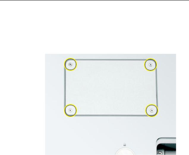
2.Remove the four screws from the memory door then remove the door.
Note: If only one memory card is installed, the factory installs it in the bottom memory slot.
Note: Memory must be removed from the top slot before removing from the bottom slot.
Memory Door and Memory Cards |
PowerBook G4 (15-inch FW 800_1.5/1.33GHz) Take Apart - 11 |

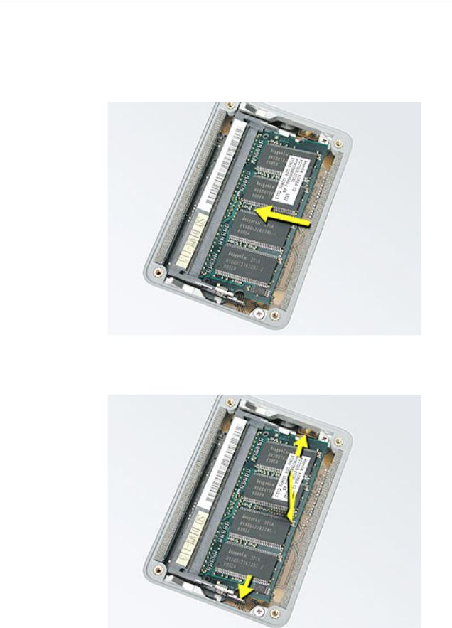
3.To remove memory cards, carefully spread the two locking tabs for the slot (top or bottom) away from the card on both sides and allow the card to pop up slightly.
4. Pull the card straight back and out of the memory slot.
12 - PowerBook G4 (15-inch FW 800_1.5/1.33GHz) Take Apart |
Memory Door and Memory Cards |

Replacement Procedure
Notes:
•The top and bottom memory cards are inserted at different angles.
•If installing two cards, install into the bottom slot first.
•Align the notch in the memory card with the tooth in the slot before inserting.
1.To install a memory card into the bottom slot, insert the card at a low angle behind the locking tabs of the top slot.
Memory Door and Memory Cards |
PowerBook G4 (15-inch FW 800_1.5/1.33GHz) Take Apart - 13 |
2.Slide the card forward to the lower slot. Firmly push the card straight into the slot until it is fully and securely seated along its length.
Note: If the back of the card drops down before it is fully seated, raise it up enough to push it fully into the slot.
3.Carefully spread the two locking tabs for the bottom slot away from the card on both sides while pushing the card straight down until the tabs click onto both sides of the card, locking it into place.
14 - PowerBook G4 (15-inch FW 800_1.5/1.33GHz) Take Apart |
Memory Door and Memory Cards |
Loading...