


PowerBook G4 (Gigabit Ethernet) - 550, 667 MHz
Updated : 04-06-2002
AppleCare
Take Apart

K Service Source
Troubleshooting
PowerBook G4 (Gigabit Ethernet)
© 2001 Apple Computer, Inc. All rights reserved.

|
Troubleshooting |
|
Symptom Charts/How to Use the Symptom Charts - 1 |
|
|
|
Symptom Charts |
|
|
|
|
How to Use the Symptom Charts |
||
|
|
The Symptom Charts included in this chapter will help you |
||
|
|
diagnose specific symptoms related to the product. |
||
|
|
The steps to solve a symptom are listed sequentially. You might not |
||
|
|
need to perform every step before the symptom is solved. Start |
||
|
|
with the first step, and then test for the symptom. If the symptom |
||
|
|
persists, replace any modules you removed, go to the next step, |
||
|
|
and test again. Continue down the list until the symptom is solved. |
||
|
|
AirPort Card |
||
AirPort Card not |
1 |
Use Software Update control panel or see the Apple Software |
||
recognized |
|
Updates web page to make sure the latest version of AirPort |
||
|
|
|
software is installed. |
|
|
|
2 |
Boot using Mac OS All extensions setting. |
|
|
|
3 |
Reseat AirPort Card. |
|
|
|
4 |
Remove and reinstall the AirPort software. |
|
|
|
5 |
Replace with known-good AirPort Card. |
|
|
|
6 |
Replace logic board. |
|
|
|
Battery |
||
Battery will not eject |
1 |
Flip over the unit and release the battery latch by sliding the |
||
|
|
|
latch towards the PC Card button. |
|
|
|
2 |
If the battery still will not eject, while holding the latch |
|
|
|
|
towards the PC Card button, use a small plastic flat-blade |
|
|
|
|
tool to pry the battery around the battery latch. |
|
|
|
3 |
Verify proper latch operation, by exercising the latch. If it |
|
|
|
|
does not move smoothly or evenly, replace rib chassis |
|
|
|
|
assembly. |
|
|
|
4 |
If the latch does exercise correctly, verify that the customer |
|
|
|
|
is not installing the battery with excessive force. |
|
DVD disc icon does not show up on desktop, or a dialog box appears to initialize disc
DVD-ROM Drive
1Use Software Update control panel to update firmware.
2Try cleaning the disc. If it is dirty or scratched, it may not mount.
3Try a different disc.

Troubleshooting |
Symptom Charts/Error Beeps - 2 |
|
|
|
|
4Select “Mac OS All” in the Extensions Manager control panel and restart.
5Replace optical drive cable.
6Replace optical drive.
Computer beeps once at startup
Error Beeps
The computer automatically performs a power-on self test when it is turned on after being fully shut down (not a restart). This section describes what to do if beeps are heard during the startup.
Note: The PowerBook G4 has two memory expansion slots and accepts 1.5-inch (or shorter) PC-100 compliant, SO-DIMM memory cards; there is no RAM on the logic board itself. Refer to Customer-Installable-Parts Memory Replacement instructions for removal and installation.
1 One beep means that no RAM is detected.
Note: There is no RAM on the logic board itself, so the computer will beep if no memory is installed in at least one of the RAM slots.
2Put the original RAM that came with the computer back in, or put in known-good and compatible RAM and restart.
•If symptom does NOT repeat, replace RAM card/s.
•If symptom repeats, replace logic board.
Computer beeps twice |
1 |
Two beeps means that EDO memory is installed in the RAM |
at startup |
|
expansion slot. The PowerBook does not accept EDO memory. |
|
2 |
Replace RAM card/s with known-good and compatible RAM |
|
|
and restart. |
|
|
• If symptom repeats, replace logic board. |
Computer beeps three |
1 |
Three beeps means that no RAM banks passed memory testing. |
times at startup |
2 |
If a RAM card is installed in the upper expansion slot (if not, |
|
|
skip to next step), remove it and restart. |
|
|
• If symptom does NOT repeat, replace RAM card. |
|
|
• If symptom repeats, replace RAM in lower RAM slot with |
|
|
known-good and compatible RAM card and restart. If |
|
|
symptom repeats, replace logic board. |
|
3 |
If a RAM card is NOT installed in the upper expansion slot, |
|
|
replace RAM in lower RAM slot with known-good and |
|
|
compatible RAM card and restart. |
|
|
• If symptom repeats, replace logic board. |

|
Troubleshooting |
Symptom Charts/Hard Drive - 3 |
|
|
|
|
|
Computer beeps four |
1 Four beeps indicates a bad checksum for the remainder of the |
||
times at startup |
boot ROM. The ROM (which is located on the logic board) is |
||
|
|
bad. |
|
|
|
2 Replace RAM card/s with known-good and compatible RAM |
|
|
|
and restart. |
|
|
|
• If symptom repeats, replace logic board. |
|
|
|
Related articles: |
|
|
|
58442: Power On Self-Test Beep Definition - Part 2 |
|
|
|
95132: PowerBook G4: Installing or Replacing Memory |
|
Hard Drive
Hard drive will not |
1 |
Boot from PowerBook G4 Software Install CD and see if the |
initialize |
|
hard drive mounts on the desktop. |
|
2 |
Launch Drive Setup and update hard drive driver. |
|
3 |
If no hard drive is found in Drive Setup, verify the hard |
|
|
drive cable connections. |
|
4 |
Replace hard drive cable. |
|
5 |
Replace hard drive. |
|
|
Important: If the computer is under warranty and data |
|
|
recovery is required, refer to Article 31077: Hard Drive Data |
|
|
Recovery & Warranty Implications, for important |
|
|
information. |
The internal hard |
1 |
Disconnect any connected peripherals. |
drive does not spin |
2 |
Try known-good power outlet. |
|
3 |
Try known-good power adapter and power cord. |
|
4 |
Boot from a Mac OS system CD. |
|
5 |
Verify Drive Setup does not recognize the hard drive. |
|
6 |
Verify cable connections. |
|
Modem |
|
No modem dial tone |
1 |
Verify known-good analog (not digital) telephone line. |
|
2 |
Verify known-good RJ11 telephone cable. |
|
3 |
Verify RJ11 cable is not plugged into Ethernet port. |
|
4 |
Inspect RJ11 connector and modem port for pin damage. |
|
5 |
Verify RJ11 telephone cable is firmly installed in the modem |
|
|
port. |
|
6 |
If using Apple Remote Access, select Ignore Dial Tone in the |
|
|
Modem control panel. If the modem connects with this settings |
|
|
selected, try another phone line. If using a terminal or |
|
|
communications program, enter atx1 to disable tone |
|
|
detection. To reset the modem back to the factory settings, |
|
|
enter atz. |
Troubleshooting |
Symptom Charts/PC Card - 4 |
|
|
|
|
PC Card will not insert into the PC Card slot
7Verify RJ11 modem cable is plugged into modem correctly.
8Replace modem.
PC Card
1Make sure the PC Card eject button is in, before attempting to insert a PC Card.
2Make sure the PC Card is right side up (cards are keyed and cannot be inserted upside down).
3Verify the PC Card is not warped or damaged in any way; if so replace the card.
4Try a different PC Card.
5Carefully raise the PC Card slot cover and check for a foreign object inside the slot.
6Check to see if the AirPort Card antenna wire is protruding up into the PC Card slot opening from below. If so, open the computer to gain access to the AirPort Card location and reposition the antenna cable so that it does not sag down into the PC Card slot area (see AirPort Card Installation Instructions).
7If the slot cover is preventing the card from being inserted, replace the top case.
8Replace Card Cage, PCMCIA assembly.
Troubleshooting |
Symptom Charts/Sound - 5 |
|
|
|
|
Sound
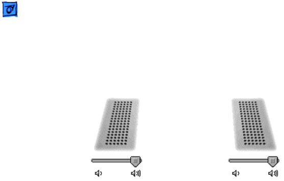
No sound heard and the Speakers section of the Sound control panel indicates that an external device is plugged in (to the headphone jack or USB ports)
1If there is nothing plugged into the headphone jack or USB ports, the picture in the Speakers section of the Sound control panel should be of the internal speakers, as shown here.
2If not, and if nothing is plugged in, try plugging in headphones or external speakers. Restart the computer. Remove the device.
3Reset PRAM (Press the power button, then hold down the Option-Command-P-R keys until you hear the startup chime at least one additional time after the initial startup chime).
4Warning: Resetting the PRAM will permanently remove a RAM disk, if present, and all of its contents. You will also need to reset the date and time (using the Date & Time control panel).
5Replace logic board.
Video
No display, or dim |
1 |
Remove any connected peripherals. |
display, but computer |
2 |
Try known-good power outlet, power adapter and power cord. |
appears to operate |
3 |
Press the F2 key (with the fn key pressed and not pressed) to |
correctly |
|
increase the screen brightness settings. |
|
4 |
Reboot the computer—hold down the Control and Command |
|
|
keys and press the Power button to restart the computer. Or, |
|
|
press and hold the Power button for 5 to 10 seconds to shut |
|
|
down the computer, then press the Power button to restart. |
|
5 |
Verify inverter cable and LVDS cable connections are seated |
|
|
properly and that the cables are not damaged (refer display |
|
|
assembly replacement instructions). |
|
6 |
Replace inverter board. |
|
7 |
Replace display assembly. |
|
8 |
Replace logic board. |

|
Troubleshooting |
|
Symptom Charts/Misc. Symptoms - 6 |
|
|
|
|
|
|
Computer appears to |
1 |
The device must be connected to the S-video port while the |
||
work, but no video on |
|
PowerBook is sleeping or off for the device to be recognized. |
||
external device |
2 |
If running Mac OS X, verify that this issue is also in Mac OS |
||
connected to the TV out |
|
9. |
|
|
port (S-video out |
3 |
Verify monitor that is used in testing is known-good and is |
||
port) |
|
supported by this computer. |
||
|
|
4 |
Try different cable(s). |
|
|
|
5 |
Replace logic board. |
|
No video on an |
1 |
In the Resolution control strip, see if the device is being |
||
external device |
|
recognized. If so select resolution. |
||
connected to the |
2 |
If running Mac OS X, verify that this issue is also in Mac OS |
||
External monitor port |
|
9. |
|
|
|
|
3 |
Verify monitor that is used in testing is known-good and is |
|
|
|
|
supported by this computer. |
|
|
|
4 |
Try another VGA monitor cable. |
|
|
|
5 |
Restart the computer and text again. |
|
|
|
6 |
Replace logic board. |
|
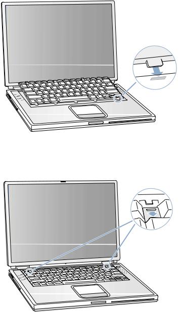
Latch not working
The Date and Time settings reset all the time
Misc. Symptoms
Note: When the display is being closed, a hook in the top of the display housing should be magnetically pulled down to the latch. When the latch button is pushed, the hook should release and retract into the display housing.
1Verify hook operation by exercising the latch mechanism.
2If the hook does not operate properly, replace the display assembly.
3If the latch or latch button does not operate properly, replace the top case assembly.
Note: Resetting the power manager or PRAM resets the date and time.
1Verify that the reset button is not stuck.
2Do a backup battery test:
•Set the date and time.
•Perform a Shut Down from the Apple menu or Special menu.
•Remove the main battery and disconnect the power adapter for 10 minutes.
•Connect the power adapter, insert the battery, and power on the computer.
•If the date and time were lost the backup battery may be dead or discharged.

Troubleshooting |
Symptom Charts/Misc. Symptoms - 7 |
|
|
|
|
AirPort Card installed and received a -3278 error
The microphone is not working
During startup boot sequence and before reaching Finder, the following dialog box appears: “The builtin memory test has detected an error”
•Remove the main battery from the unit and leave the PowerBook plugged in for at least 5 hours.
Note: If a discharged main battery is installed in the computer, recharging the backup battery may take up to 48 hours to completely charge. It is okay to use it while it is charging.
• If the date and time still reset, replace the backup battery. 3 If not the backup battery, replace PMU Card.
Note: For main and backup battery part numbers, refer to article 11751: Macintosh Family: Batteries and Part Numbers.
1Use Software Update control panel or see the Apple Software Updates web page to make sure the latest version of AirPort software is installed.
2Boot using Mac OS All extensions setting.
3Reseat AirPort Card.
4Remove and reinstall the AirPort software.
5Replace with known-good AirPort Card.
6Replace logic board.
1Check the Sound control panel and verify that the selection for input is the built-in microphone.
2Check the signal level and level meter and adjust the gain.
3Remove Sound Preferences from the Preferences folder and restart.
4Reset PRAM (Press the power button, then hold down the Option-Command-P-R keys until you hear the startup chime at least one additional time after the initial startup chime).
5If no sound as well as microphone is not working, verify cable connections.
6Replace top case.
1If a RAM card is installed in the upper expansion slot (if not, skip to next step), remove it and restart. Refer to Customer- Installable-Parts Memory Replacement instructions.
•If symptom does NOT repeat, replace RAM card.
•If symptom repeats, replace RAM in lower RAM slot with known-good SDRAM SO-DIMM RAM card and restart.
- If symptom repeats, replace logic board.
2If a RAM card is NOT installed in the upper expansion slot, replace RAM in lower RAM slot with known-good SDRAM SODIMM RAM card and restart. Refer to Customer-Installable- Parts Memory Replacement instructions.
•If symptom repeats, replace logic board.
LCD anomalies |
|
Go to : Pixel anomalies |
|
||
|
|
|
A certain number of pixel anomalies are inherent in liquid crystal display technology and vary by many factors, including type of technology.
Many anomalies observed by customers are considered normal or are the result of lint or dust particles resting on the front of the display. It is important to understand what type of anomaly a customer sees in order to determine whether further analysis is necessary. In many cases all that may be necessary is a gentle cleaning of the display face using the provided cleaning cloth.
IMPORTANT : Providing a replacement display to satisfy a customer may not be effective because the replacement display may have more or different types of visible anomalies than the original display, and still be within specifications.
Knowledge Base Article 22194 can be indicated to customers as public explanation from Apple side.
Industry standards used by all manufacturers are specifying a certain number of minor defects, as generally accepted or creating an acceptable situation. This means that the level of quality in the industry includes some level of pixel-defect.
The following sentences can be used with customers’ complains
Copied from SONY documentation (Sony VAIO web Support)
•High precision technology is used to manufacture these LCDs to maintain a high standard of operation. However in all LCD panels there may be a small number of pixels that do not change color. This is a normal occurrence for all LCD displays from all manufacturers and should not be noticeable or objectionable under normal operation.
•Sometimes the pixels are noticeable only during booting or on an all white or all black screen.
•The LCD screen is manufactured using high precision technology. However, there may be some tiny black spots and/or bright spots (red, blue or green in colour) that constantly appear on the LCD screen. These spots occur normally in the manufacturing process and do not effect the recorded picture in any way. Effective number of pixels is 99.99% or more.
Copied from COMPAQ documentation (Compaq FAQ on Compaq’s web Support)
•Note that if you have the smallest number of dead pixels, your replacement display panel may have more, use your judgement before deciding that you have a defective panel.
Copied from DELL documentation (Dell web : http://support.euro.dell.com/fr/fr/kb/document.asp?DN=FA1018431)
•The liquid crystal display (LCD) screens built into portable computers and flat-panel monitors are manufactured using rigid quality control standards. These manufacturing standards ensure that the LCD screen is clear and viewable.
•During the manufacturing process, it is not uncommon for one or more pixels to be fixed in an unchanging state. The visible result is a fixed pixel that appears as an extremely tiny discolored spot, either a dark spot or a bright spot.
Copied from TOSHIBA documentation (Toshiba web Support)
•Due to current manufacturing methods and the high number of transistors in the TFT Color LCD, a few nonconforming pixels may be visible. There are over a million transistors in a typical TFT screen. When any one of those transistors is not lighting as designed, the pixel is called nonconforming. Nonconforming pixels typically appear as tiny colored dots (red, blue, green, etc.) or as black dots in contrast to the projected background color of the LCD module.
•Quality inspections, performed by the LCD module manufacturers, include limits for nonconforming pixels. Nonconforming pixel limits (10 to 18 pixels) are set solely by the LCD module manufacturers and not by specific computer manufacturers. These limits are defined by the manufacturing processes and are specific to screen characteristics which include :
*physical size of module.
*display type (SVGA, XGA, VGA).
*screen resolutions available.
•LCD Module manufacturers continually strive to upgrade processes used in manufacturing as well as the Quality Specifications which include the limits on nonconforming pixels allowed for LCD modules for use in portable computer displays.
(End
Pixel anomalies |
|
Go to : LCD anomalies |
|
||
|
|
|
When speaking with Apple Technical Support, it may be necessary to use a pocket microscope, jeweler's loupe, or other magnifying device to properly identify and count each subpixel anomaly.
Displaying all white, red, green, and blue screens makes locating and viewing pixel anomalies easier.
A subpixel that is always on should be referred to as a bright subpixel anomaly. A subpixel that is always off should be referred to as a dark subpixel anomaly.
When necessary, portable and display products may be dispatched for evaluation by the Apple Repair Center.
(End

Keyboard
English
AppleCare
this sheet carefully. Failure to follow these instructions could damage your equipment and void its
instructions covering customer-installable parts are available at http://www.info.apple.com/install-
keep small parts away from children.
this procedure is a jeweler’s flat-blade screwdriver (if keyboard is locked).
Keyboard
down your computer before opening it to avoid damaging its internal components or shut down the computer, the internal components can be very hot. Let the computer
.
a clean, flat surface.
and wait thirty minutes before continuing.
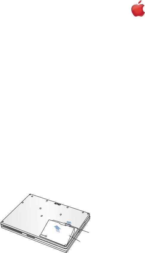
cord and any other cables connected to the computer. turn it over.
Figure 1A) to the right to remove the battery (Figure 1B). prevent you from accidentally turning on the computer.
the battery before shutting down your computer may result in data loss.
Figure 1
A
B
.
can access the keyboard.
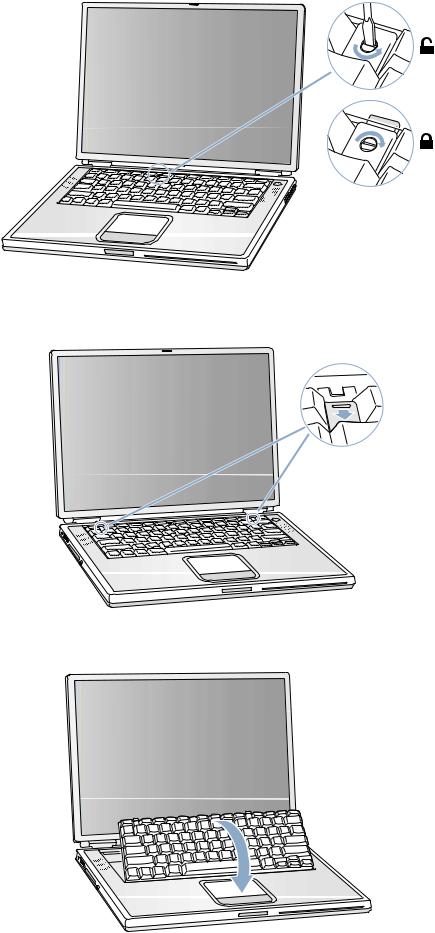
locking screw, located in the small plastic tab to the left of the Num Lock key (Figure 2), is not in PowerBook comes with the keyboard unlocked, so unless you or someone else locked the key-
step.
PowerBook G4 (Gigabit Ethernet) - Keyboard |
1 |

To unlock the keyboard, turn the screw 1/2 turn.
Figure 2
9.Release the keyboard by pulling down on the keyboard release tabs (located to the left of the F1 and F12 keys) (Figure 3), then lift the top portion of the keyboard up slightly, and toward the display.
Figure 3
®
10. Flip the keyboard over and lay it on the palm rests and trackpad (Figure 4).
Figure 4
2 |
PowerBook G4 (Gigabit Ethernet) - Keyboard |
B073-0635 Rev. A |
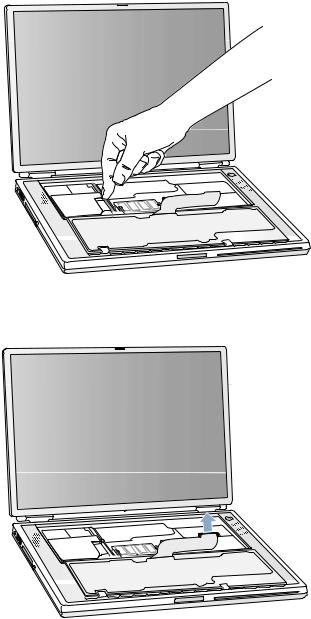
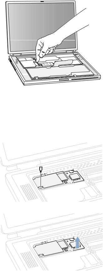
11.Touch the computer’s inside framework (a dull gray conductive composite material) to discharge any static electricity, as shown (Figure 5).
Important : To avoid electrostatic discharge damage, always ground yourself by touching the computer’s framework before you touch any parts or install any components inside the computer. To avoid static electricity building back up in your body, do not walk around the room until you have completed your installation and closed the computer.
Figure 5
12. Locate the keyboard cable connector (Figure 6).
Figure 6
13.Pull up on the connector, from side to side if needed, to disconnect it from the computer.
14.Set the keyboard aside.
B073-0635 Rev. A |
PowerBook G4 (Gigabit Ethernet) - Keyboard |
3 |
Installing the Replacement Keyboard
1.Lay the replacement keyboard in the correct orientation over the keyboard opening, then flip it toward you and lay it face down on the palm rests and trackpad to expose its connector cable (Figure 7).
Figure 7
2.Firmly insert the keyboard cable connector into its connector on the computer.
3.Flip the keyboard back toward the keyboard opening in the case.
4.Hold the keyboard at an angle above the keyboard opening, and insert the tabs on the bottom edge of the keyboard into the slots below the edge of the opening (Figure 8).
Important : Make sure that all the tabs are seated and that the keyboard rests flush against the edge of the opening.
Figure 8
5. Lay the keyboard flat into the keyboard opening.
4 |
PowerBook G4 (Gigabit Ethernet) - Keyboard |
B073-0635 Rev. A |
6. Pull down on the keyboard release tabs and then press down on the top portion of the keyboard (Figure 9).
Figure 9
®
7.Release the tabs to secure the keyboard in place.
8.Close the display and turn the PowerBook over.
9.Replace the battery into the battery compartment (Figure 10).
Important : Make sure that the battery locks securely into place and that the battery latch is slid all the way into the locked position.
Figure 10
10. Reconnect the power cord and any other cables that were connected, and restart your computer.
Warning : Never turn on your computer unless all of its internal and external parts are in place and it is closed. Operating the computer when it is open or missing parts can damage your computer or cause injury.
B073-0635 Rev. A |
PowerBook G4 (Gigabit Ethernet) - Keyboard |
5 |
Apple Computer, Inc.
© 2001 Apple Computer, Inc. All rights reserved.
Under the copyright laws, this document may not be copied, in whole or in part, without the written consent of Apple.
The Apple logo is a trademark of Apple Computer, Inc., registered in the U.S. and other countries. Use of the “keyboard” Apple logo (Option-Shift-K) for commercial purposes without the prior written consent of Apple may constitute trademark infringement and unfair competition in violation of federal and state laws.
Every effort has been made to ensure that the information in this document is accurate. Apple is not responsible for printing or clerical errors.
Apple Computer, Inc. 1 Infinite Loop
Cupertino, CA 95014-2084 USA
+ 1 408 996 1010 http://www.apple.com
Apple, the Apple logo, and PowerBook are trademarks of Apple Computer, Inc., registered in the U.S. and other countries.
6 |
PowerBook G4 (Gigabit Ethernet) - Keyboard |
B073-0635 Rev. A |

Memory
English
AppleCare
this sheet carefully. Failure to follow these instructions could damage your equipment and void its
instructions covering customer-installable parts are available at http://www.info.apple.com/install-
keep small parts away from children.
this procedure is a jeweler’s flat-blade screwdriver (if keyboard is locked).
down your computer before opening it to avoid damaging its internal components or shut down the computer, the internal components can be very hot. Let the computer
.
a clean, flat surface.
and wait thirty minutes before continuing.
cord and any other cables connected to the computer. turn it over.
Figure 1A) to the right to remove the battery (Figure 1B). prevent you from accidentally turning on the computer.
the battery before shutting down your computer may result in data loss.
Figure 1
A
B
.
can access the keyboard.
locking screw, located in the small plastic tab to the left of the Num Lock key (Figure 2), is not in PowerBook comes with the keyboard unlocked, so unless you or someone else locked the key-
step.
PowerBook G4 (Gigabit Ethernet) - Memory |
1 |
 02-06 Service Manual")
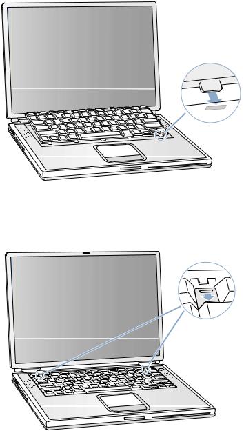
To unlock the keyboard, turn the screw 1/2 turn.
Figure 2
9.Release the keyboard by pulling down on the keyboard release tabs (located to the left of the F1 and F12 keys) (Figure 3), then lift the top portion of the keyboard up slightly, and toward the display.
Figure 3
®
10. Flip the keyboard over and lay it on the palm rests and trackpad (Figure 4).
Figure 4
2 |
PowerBook G4 (Gigabit Ethernet) - Memory |
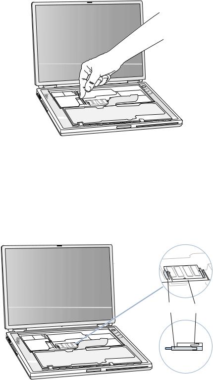
11. Touch the computer’s inside framework (a dull gray conductive composite material) to discharge any static electricity, as shown (Figure 5).
Important : To avoid electrostatic discharge damage, always ground yourself by touching the computer’s framework before you touch any parts or install any components inside the computer. To avoid static electricity building back up in your body, do not walk around the room until you have completed your installation and closed the computer.
Figure 5
Removing the Installed Memory Card
1.To remove a memory card, locate the brackets that secure the card on both sides (Figure 6). Carefully spread the brackets apart until the card releases on each side. Pull the card up and out.
Note : If there is a memory card in the upper memory slot (Figure 6A), it must be removed before removing a card in the lower slot (Figure 6B).
Figure 6
B A
PowerBook G4 (Gigabit Ethernet) - Memory |
3 |
Installing the Replacement Memory Card
Warning : When handling a memory card, do not touch its gold connectors. Handle the card only by the edges.
1.To install the memory card, line up the notch in the card with the small tab in the memory slot. Hold the card at a 30-degree angle (Figure 7A), and then push the card into the slot until it is firmly seated.
Note : You may feel some resistance. If you are having trouble inserting the card, try pushing one side at a time.
Figure 7
A
2. Gently push the card down until the two brackets on either side of the card lock into place (Figure 8).
Figure 8
4 |
PowerBook G4 (Gigabit Ethernet) - Memory |
Closing the Computer
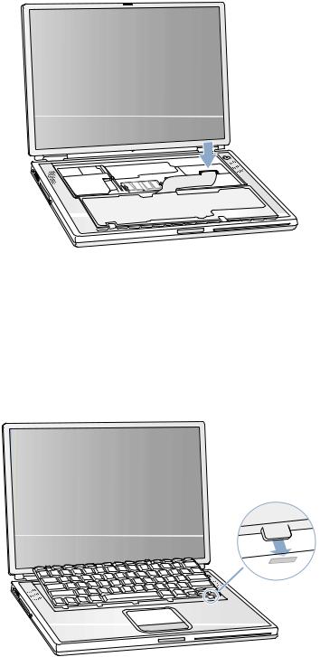
1.Flip the keyboard back toward the keyboard opening in the case.
2.Hold the keyboard at an angle above the keyboard opening, and insert the tabs on the bottom edge of the keyboard into the slots below the edge of the opening (Figure 9).
Important : Make sure that all the tabs are seated and that the keyboard rests flush against the edge of the opening.
Figure 9
3.Lay the keyboard flat into the keyboard opening.
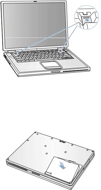
4.Pull down on the keyboard release tabs and then press down on the top portion of the keyboard (Figure 10).
Figure 10
®
5.Release the tabs to secure the keyboard in place.
6.Close the display and turn the PowerBook over.
PowerBook G4 (Gigabit Ethernet) - Memory |
5 |

7. Replace the battery into the battery compartment (Figure 11).
Important : Make sure that the battery locks securely into place and that the battery latch is slid all the way into the locked position.
Figure 11
8. Reconnect the power cord and any other cables that were connected, and restart your computer.
Warning : Never turn on your computer unless all of its internal and external parts are in place and it is closed. Operating the computer when it is open or missing parts can damage your computer or cause injury.
Apple Computer, Inc.
© 2001 Apple Computer, Inc. All rights reserved.
Under the copyright laws, this document may not be copied, in whole or in part, without the written consent of Apple.
The Apple logo is a trademark of Apple Computer, Inc., registered in the U.S. and other countries. Use of the “keyboard” Apple logo (Option-Shift-K) for commercial purposes without the prior written consent of Apple may constitute trademark infringement and unfair competition in violation of federal and state laws.
Every effort has been made to ensure that the information in this document is accurate. Apple is not responsible for printing or clerical errors.
Apple Computer, Inc. 1 Infinite Loop
Cupertino, CA 95014-2084 USA
+ 1 408 996 1010 http://www.apple.com
Apple, the Apple logo, and PowerBook are trademarks of Apple Computer, Inc., registered in the U.S. and other countries.
6 |
PowerBook G4 (Gigabit Ethernet) - Memory |
Modem
English
AppleCare
this sheet carefully. Failure to follow these instructions could damage your equipment and void its
instructions covering customer-installable parts are available at http://www.info.apple.com/install-
keep small parts away from children.
(if keyboard is locked) wrench, or needle nose pliers
down your computer before opening it to avoid damaging its internal components or shut down the computer, the internal components can be very hot. Let the computer
.
a clean, flat surface.
and wait thirty minutes before continuing.
cord and any other cables connected to the computer. turn it over.
Figure 1A) to the right to remove the battery (Figure 1B). prevent you from accidentally turning on the computer.
the battery before shutting down your computer may result in data loss.
Figure 1
A
B
.
can access the keyboard.
locking screw, located in the small plastic tab to the left of the Num Lock key (Figure 2), is not in PowerBook comes with the keyboard unlocked, so unless you or someone else locked the key-
step.
PowerBook G4 (Gigabit Ethernet) - Modem |
1 |
To unlock the keyboard, turn the screw 1/2 turn.
Figure 2
9.Release the keyboard by pulling down on the keyboard release tabs (located to the left of the F1 and F12 keys) (Figure 3), then lift the top portion of the keyboard up slightly, and toward the display.
Figure 3
®
10. Flip the keyboard over and lay it on the palm rests and trackpad (Figure 4).
Figure 4
2 |
PowerBook G4 (Gigabit Ethernet) - Modem |
B073-0634 Rev. A |
11.Touch the computer’s inside framework (a dull gray conductive composite material) to discharge any static electricity, as shown (Figure 5).
Important : To avoid electrostatic discharge damage, always ground yourself by touching the computer’s framework before you touch any parts or install any components inside the computer. To avoid static electricity building back up in your body, do not walk around the room until you have completed your installation and closed the computer.
Figure 5
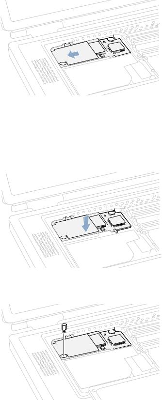
Removing the Installed Modem
Warning : You must remove and install the modem carefully to avoid damaging delicate parts, including the modem connector and connector cable.
1. Locate the modem and remove the 5 mm hexnut screw (Figure 6).
Figure 6
2. Pull up on the right, front corner of the modem to disconnect it from the logic board (Figure 7).
Figure 7
B073-0634 Rev. A |
PowerBook G4 (Gigabit Ethernet) - Modem |
3 |
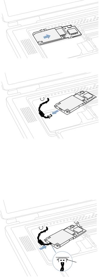
3.Pull the modem up and to the right slightly to reveal the modem connector cable attached to the left end of the modem (Figure 8).
Figure 8
4. Carefully disconnect the modem cable connector (Figure 9) and remove the modem from the computer.
Figure 9
Installing the Replacement Modem
1. Connect the modem cable connector to the modem (Figure 10).
Note : The connector plugs into the socket located on the top of the modem’s circuit board. The connector and socket are keyed to fit with the keys up (Figure 10A) .
Figure 10


 A
A
4 |
PowerBook G4 (Gigabit Ethernet) - Modem |
B073-0634 Rev. A |
2.Carefully guide the cable into the space under the edge of the keyboard opening and lay the modem into the modem opening (Figure 11).
Figure 11
3.Line up the hexnut screw hole, in the left front corner of the modem, with the hole in the logic board. The modem should lie flat.
Note : Visually verify that the modem connector cable is still attached.
4.Press down on the front edge of the modem, slightly left of center, to firmly connect it to the logic board (Figure 12).
Note : You may need to maneuver the modem around slightly until you feel the connectors match up.
Figure 12
5. Install the hexnut screw (Figure 13).
Note : It may be helpful to use a finger tip to hold the top of the screw straight and steady while turning the screw.
Figure 13
B073-0634 Rev. A |
PowerBook G4 (Gigabit Ethernet) - Modem |
5 |
Closing the Computer
1.Flip the keyboard back toward the keyboard opening in the case.
2.Hold the keyboard at an angle above the keyboard opening, and insert the tabs on the bottom edge of the keyboard into the slots below the edge of the opening (Figure 14).
Important : Make sure that all the tabs are seated and that the keyboard rests flush against the edge of the opening.
Figure 14
3.Lay the keyboard flat into the keyboard opening.
4.Pull down on the keyboard release tabs and then press down on the top portion of the keyboard (Figure 15).
Figure 15
®
5.Release the tabs to secure the keyboard in place.
6.Close the display and turn the PowerBook over.
6 |
PowerBook G4 (Gigabit Ethernet) - Modem |
B073-0634 Rev. A |
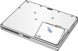
7. Replace the battery into the battery compartment (Figure 16).
Important : Make sure that the battery locks securely into place and that the battery latch is slid all the way into the locked position.
Figure 16
8. Reconnect the power cord and any other cables that were connected, and restart your computer.
Warning : Never turn on your computer unless all of its internal and external parts are in place and it is closed. Operating the computer when it is open or missing parts can damage your computer or cause injury.
Replacing International Modems
After you have replaced a modem in Europe or Asia, open the software utility Modem Country Selector and verify that the modem is set to the correct country. Modem Country Selector is located in the Apple Extras folder on your hard drive or can be downloaded as part of the Apple Modem Updater software bundle at http://asu.info.apple.com.
Apple Computer, Inc.
© 2001 Apple Computer, Inc. All rights reserved.
Under the copyright laws, this document may not be copied, in whole or in part, without the written consent of Apple.
The Apple logo is a trademark of Apple Computer, Inc., registered in the U.S. and other countries. Use of the “keyboard” Apple logo (Option-Shift-K) for commercial purposes without the prior written consent of Apple may constitute trademark infringement and unfair competition in violation of federal and state laws.
Every effort has been made to ensure that the information in this document is accurate. Apple is not responsible for printing or clerical errors.
Apple Computer, Inc. 1 Infinite Loop
Cupertino, CA 95014-2084 USA
+ 1 408 996 1010 http://www.apple.com
Apple, the Apple logo, and PowerBook are trademarks of Apple Computer, Inc., registered in the U.S. and other countries.
B073-0634 Rev. A |
PowerBook G4 (Gigabit Ethernet) - Modem |
7 |
 Loading...