


CW-C83GU
Table of contents
 Loading...
Panasonic CW-C83GU, CW-XC78HU, CW-XC83HU, CW-XC83HK, CW-XC63HK User Manual
...
INSTALLATION AND
OPERATING INSTRUCTIONS
MANUEL D'INSTALLATION ET D'UTILISATION
Room Air Conditioner
Climatiseur de fenêtre
Model, Modèle:CW-XC63HU, CW-XC63HK, CW-C83GU, CW-XC83GU,
CW-XC83HU, CW-XC83HK, CW-XC78HU
Please read these operating instructions thoroughly
before using your air conditioner and keep for future reference.
Il est recommandé de lire attentivement ce manuel avant
d'utiliser l'appareil. Conservez ce manuel.
For U.S customers :
For assistance, please call : 1-800-211-PANA(7262) or
Register your product at : http://www.panasonic.com/register
For customers in Canada :
For assistance, please call : 905-624-5505
R

2
Safety Precautions
About the Controls on the Air Conditioner
Features and Installation
Before you call for service...
FOR YOUR RECORDS
Staple your receipt to this page in case you need it later.
Write down the model and serial numbers here:
Model #
Serial #
You can find them on a label on the side of each unit.
Dealer's Name
Date Purchased
Inside you will find many helpful hints on how to use and
maintain your air conditioner properly. Just a little preventive
care on your part can save you a great deal of time and
money over the life of your air conditioner.
You'll find many answers to common problems in the chart
of troubleshooting tips. If you review our chart of
Troubleshooting Tips first, you may not need to call for
service at all.
READ THIS MANUAL
CAUTION
• Contact the authorized Service technician for repair or
maintenance of this unit.
• The air conditioner is not intended for use by young
children or infirm persons without supervision.
• Young children should be supervised to ensure that they
do not play with the air conditioner.
Safety Precautions
Safety Precautions.............3
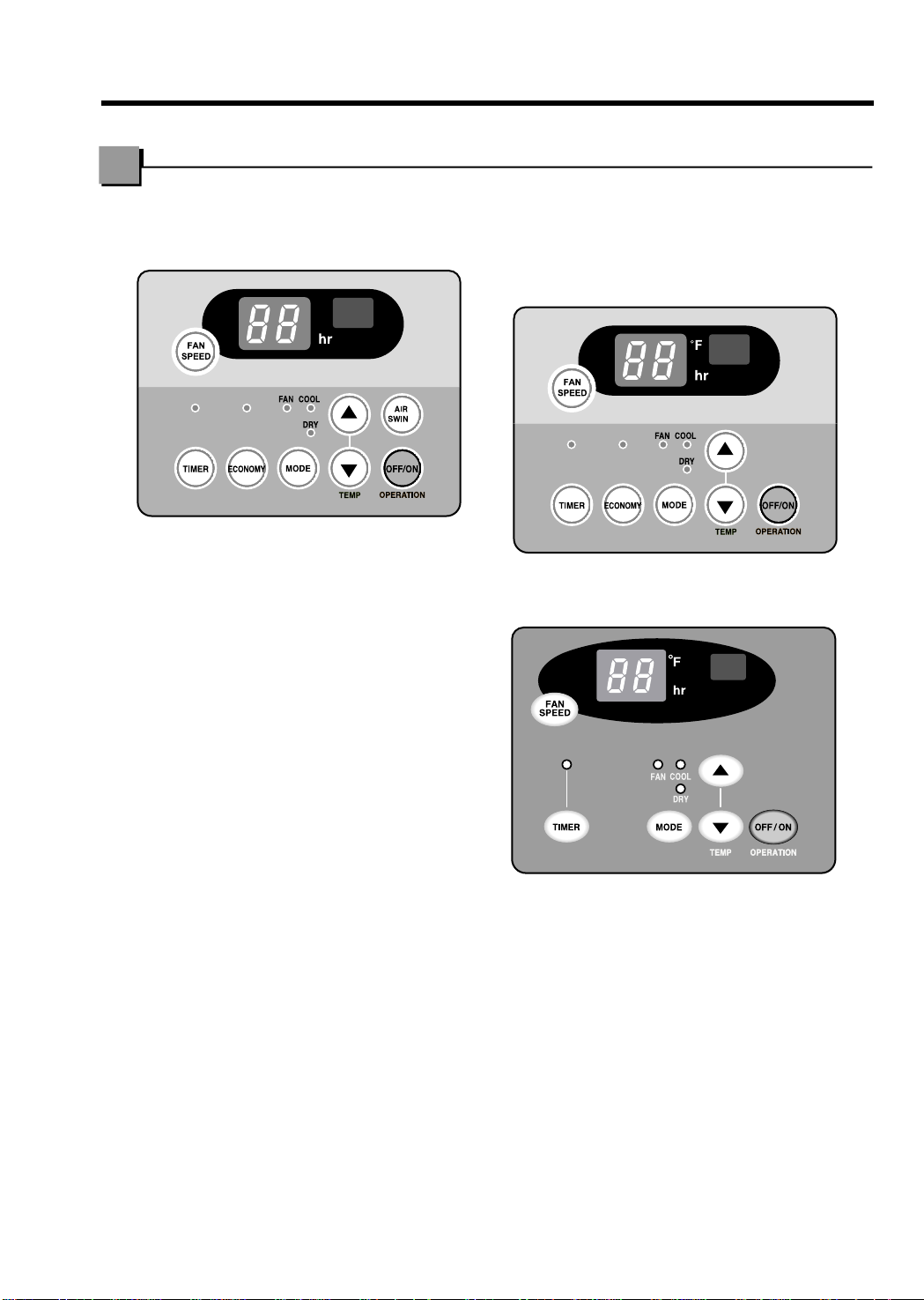
About the Controls on
the Air Conditioner
Controls..............................5
Remote Controller..............7
Ventilation ..........................8
Air Direction........................8
How to Secure Drain Pipe
....8
Care and Maintenance
Air Filter Cleaning...............9
Features
Features...........................10
Installation
How to Install the Unit......11
Window Requirements.....11
Installation Kit Contents ...12
Suggested Tool
Requirements...................12
Cabinet Installation...........13
Electrical Data..................15
Electrical Safety ...............16
Before you call for
service...
Normal Operation.............17
Abnormal Operation.........17
WARNING
3
Safety Precautions
Safety Precautions
To prevent injury to the user or other people and property damage, the following instructions must be
followed.
■ Incorrect operation due to ignoring of instruction will cause harm or damage. The seriousness is classified
by the following indications.
WARNING : This symbol indicates the possibility of death or serious injury.
CAUTION
:
This symbol indicates the possibility of injury or damage to
property only.
■ Meanings of symbols used in this manual are as shown below.
Be sure not to do this.
Be sure to follow the instructions.
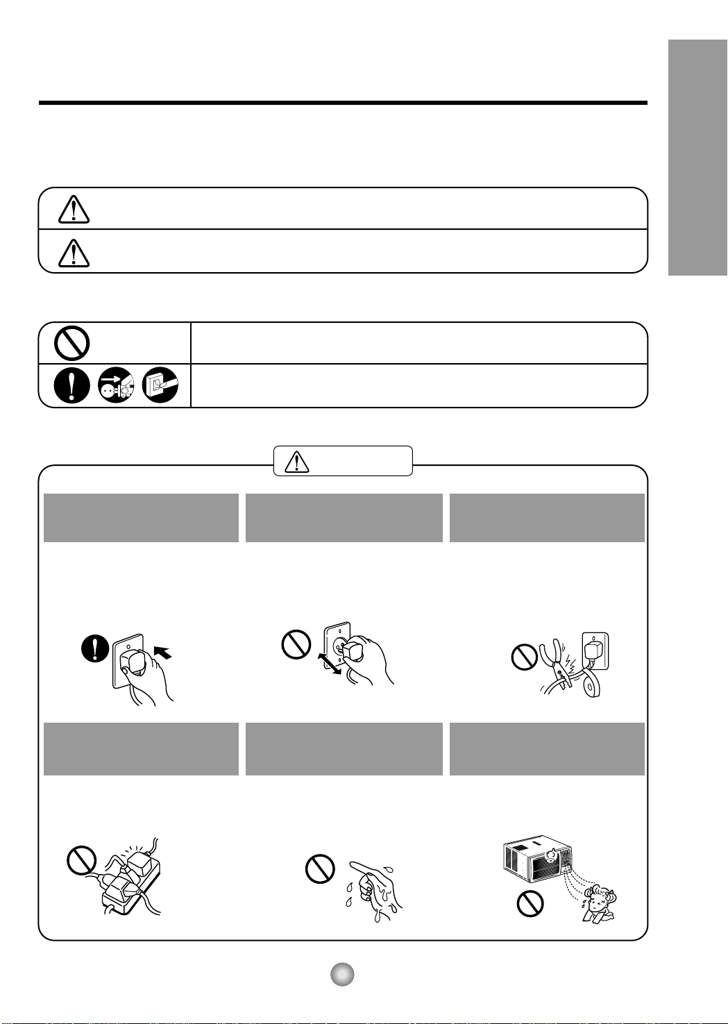
Plug in the power plug
properly.
• Otherwise, it will cause electric
shock or fire due to heat
generation.
Do not operate or stop the
unit by inserting or pulling
out the power plug.
• It will cause electric shock or fire
due to heat generation.
Do not damage or use an
unspecified power cord.
• It will cause electric shock or fire.
•
If the power cord is damaged, it must
be replaced by the manufacturer or
an authorized service center or a
similarly qualified person in order to
avoid a hazard.
Do not modify power cord
length or share the outlet
with other appliances.
• It will cause electric shock or fire
due to heat generation.
Do not operate with wet
hands or in a damp
environment.
• It will cause electric shock.
Do not direct air flow at room
occupants.
• This could lead to health
problems.
4
Safety Precautions


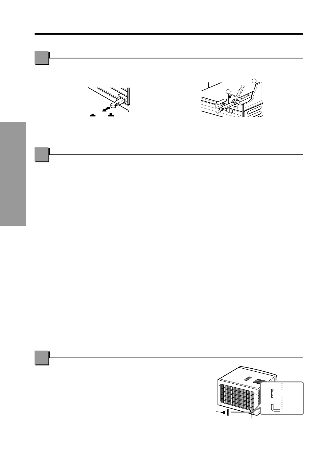
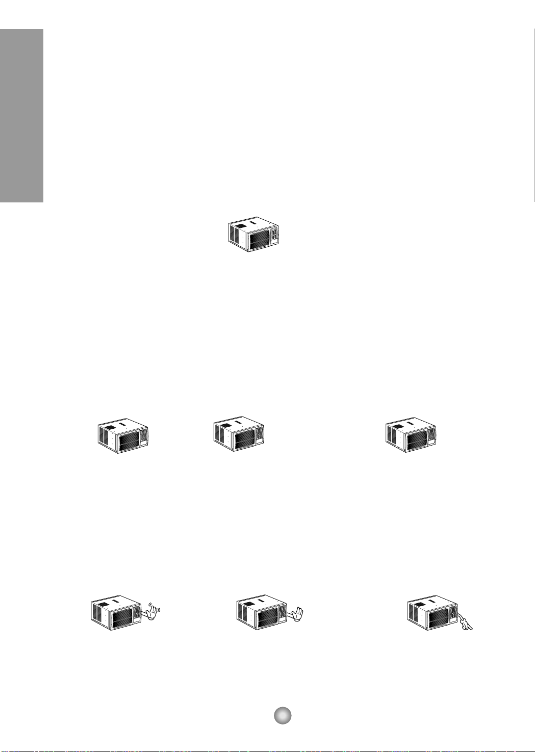
VENTCLOSE
OPEN
Part
A
Part
B
Drain pipe
Drain cap

10
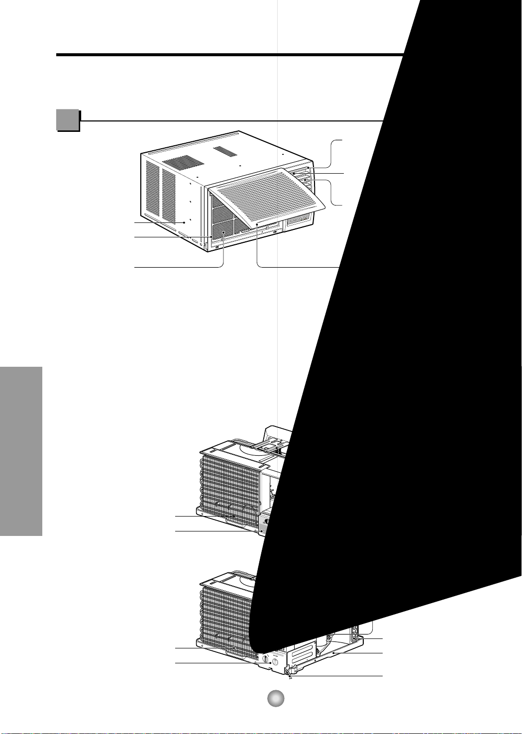
Features and Installation
Learning parts name prior to installation will help you understand the installation procedure.
Features
Features
CABINET
FRONT GRILLE
AIR FILTER
AIR INTAKE
(INLET GRILLE)
AIR DISCHARGE
HORIZONTAL AIR DEFLECTOR
(VERTICAL LOUVER)
VERTICAL AIR DEFLECTOR
(HORIZONTAL LOUVER)
EVAPORATOR
POWER CORD
BASE PAN
CONDENSER
COMPRESSOR
BRACE
CONTROL BOARD
EVAPORATOR
CONTROL BOARD
POWER CORD
BASE PAN
CONDENSER
COMPRESSOR
BRACE
About 12.7mm (1/2")
76.2cm (30")~
152.4cm (60")
Awning
Cooled air
Fence
Over 50.8cm (20")
Heat
radiation
55.8cm (22") to
91.44cm (36")
Offset
12.7mm (1/2") to
31.8mm (1
1
/4")
Sill
Exterior
Interior wall
47cm (181/2") min.
(Without frame curtain)
Stool
38cm (15") min
(With frame curtain)
11
INSTALLATION
Features and Installation
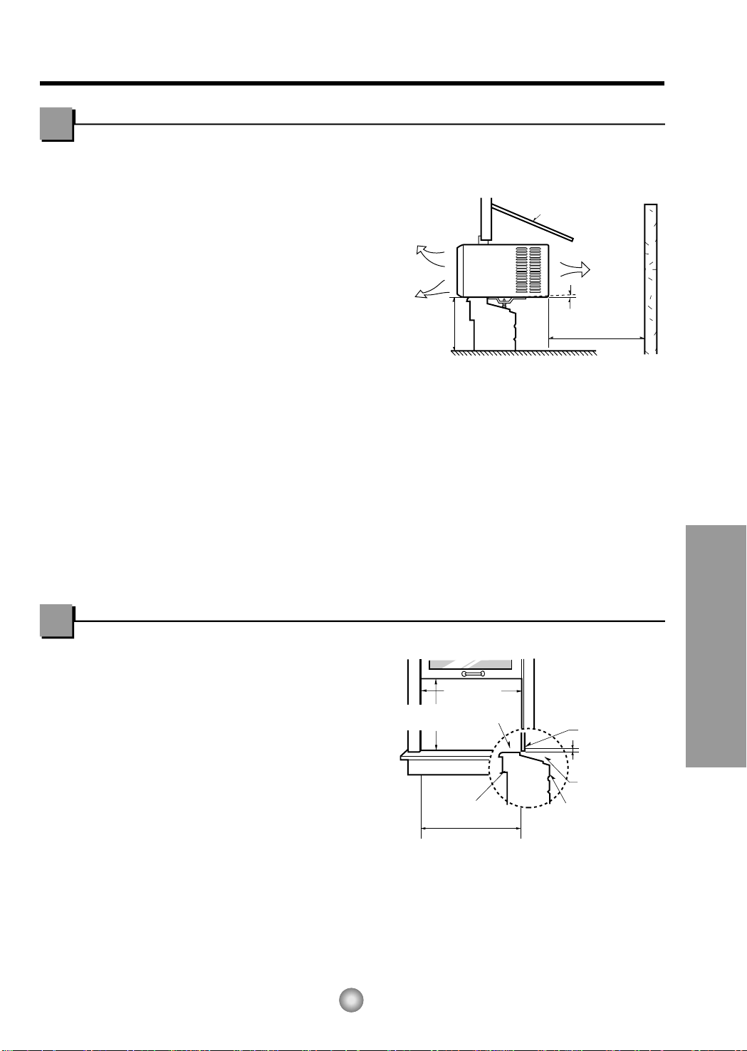
1. To prevent vibration and noise, make sure
the unit is installed securely and firmly
2. Install the unit where the sunlight does not
shine directly on the unit.
3. The outside of the cabinet must extend
outward for at least 28cm (11") and there
should be no obstacles, such as a fence or
wall, within 50.8cm (20") from the back of
the cabinet because it will prevent heat
radiation of the condenser.
Restriction of outside air will greatly reduce
the cooling efficiency of the air conditioner.
CAUTION: All side louvers of the cabinet must remain exposed to the outside of the
structure.
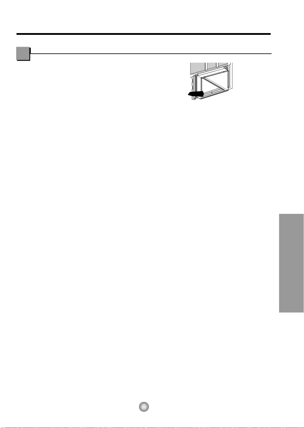
4. Install the unit a little slanted so the back is slightly lower than the front
(about 12.7mm (1/
2")).
This will force condensed water to flow to the outside.
5. Install the unit with the bottom about 76.2cm (30")~152.4cm (60") above the floor level.
Window Requirements
NOTE: All supporting parts should be secured to firm wood, masonry, or metal.
This unit is designed for installation in
standard double hung windows with actual
opening widths from 55.88cm (22") to
91.44cm (36").
The top and bottom window sash must open
sufficiently to allow a clear vertical opening of
38cm (15") from the bottom of the upper sash
to the window stool.
How to Install the Unit
9
10
9
5
5
5
11
11
(Type A)
(Type A)
13
1
2 3 4
8 13
14
10
765
9
12
11
Shipping
Screws
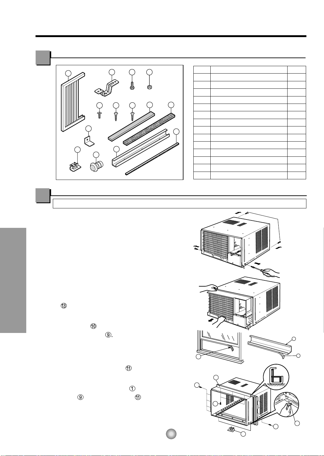
PREPARATION OF CHASSIS
1. Remove the screws which fasten the cabinet
at both sides and at the back.
2. Slide the unit from the cabinet by gripping the
base pan handle and pulling while bracing the
cabinet.
3. Cut the window sash seal to the proper
length.
Peel off the backing and attach the FOAM-PE
to the underside of the window sash.
4. Remove the backing from the top upper guide
FOAM-PE and attach it to the bottom of
the upper guide
5. Attach the upper guide onto the top of the
cabinet with 3 type A screws.
6. Insert the frame guides into the bottom of
the cabinet.
7. Insert the Frame Curtain into the upper
guide and frame guides .
8. Fasten the curtains to the unit with 4 Type
A screws.
12
Features and Installation
Suggested Tool Requirements
Installation Kit Contents
SCREWDRIVER(+, -), RULER, KNIFE, HAMMER, PENCIL, LEVEL
NO. NAME OF PARTS Q'TY
1 FRAME CURTAIN 2
2 SILL SUPPORT 2
3 BOLT 2
4 NUT 2
5
SCREW(TYPE A) (10mm(2/5"))
16
6
SCREW(TYPE B)
3
7
SCREW(TYPE C)
5
8
FOAM-STRIP
1
9 UPPER GUIDE 1
10
FOAM-PE (466mm x 10mm x 2mm)
1
11 FRAME GUIDE 2
12
WINDOW LOCKING BRACKET
1
13
FOAM-PE
(920mm x 30mm x 2mm)
1
14 DRAIN PIPE 1
D5.1mm(0.2")
16mm(0.63")
D4.1mm(0.17")
16mm(0.63")
13
Features and Installation
Type C
7
Screw (Type A)
Screw (Type A)
Power cord
Foam-Strip
8
Window locking bracket
12
14
Features and Installation
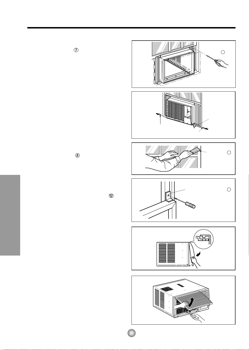
9. Attach each Frame curtain to the window
sash using screws
(Type C). (See Fig. 6)
CAUTION: DO NOT DRILL A HOLE IN THE
BOTTOM PAN.
The unit is designed to operate
with approximately 12.7mm (1/
2") of
water in bottom pan.
10. Slide the unit into the cabinet. (See Fig. 7)
CAUTION: For security purposes, reinstall
screws (Type A) at cabinet's sides.
11. Cut the foam-strip
to the proper length
and insert between the upper window sash
and the lower window sash.
(See Fig. 8)
12. Attach the window locking bracket with
a type C screw. (See Fig. 9)
13. Attach the front grille to the cabinet by
inserting the tabs on the grille into the tabs
on the front of the cabinet. Push the grille
in until it snaps into place. (See Fig.10)
NOTE: Please refer p.8 for setting ventilation
kit.
14. Lift the inlet grille and secure it with a type
A screw through the front grille.
(See Fig. 11)
15. Window installation of room air conditioner
is now completed. See ELECTRICAL DATA
for attaching power cord to electrical outlet.
Fig. 6
Fig. 7
Fig. 8
Fig. 9
Fig. 10
Fig. 11
15
Features and Installation
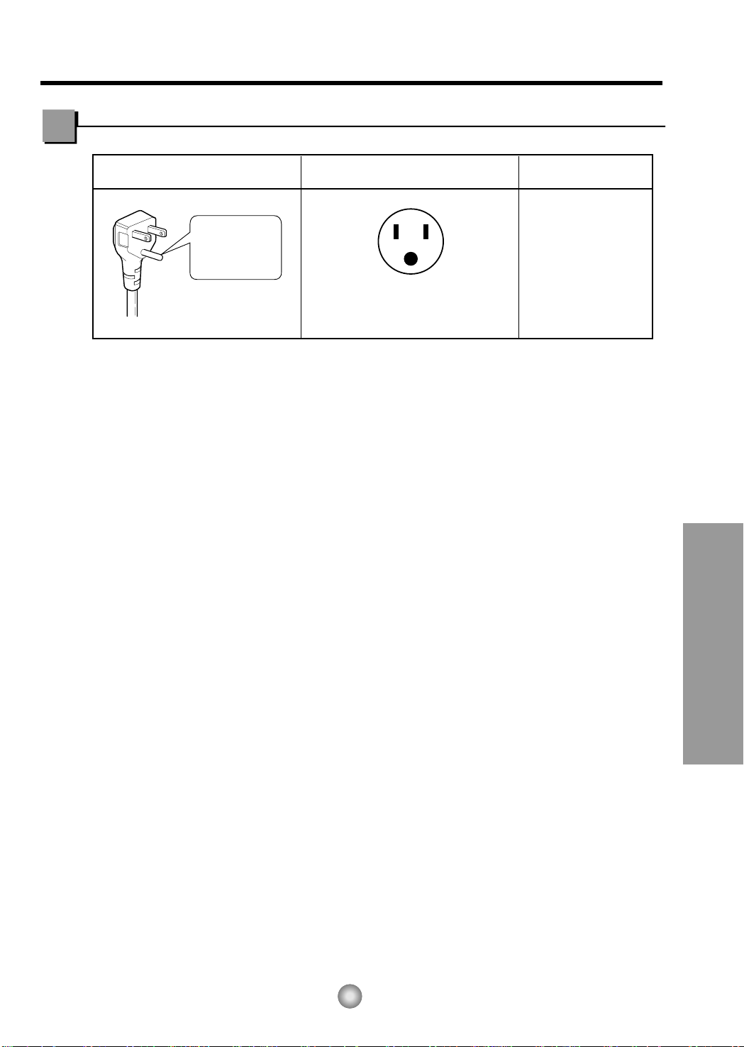
Do not under any
circumstances cut
or remove the
grounding prong
from the plug.
Line Cord Plug Use Wall Receptacle Power Supply
Power supply cord with
3-prong grounding plug
Standard 125V, 3-wire grounding
receptacle rated 15A, 125V AC
Use 15 AMP, time
delay fuse or circuit
breaker.
Electrical Data
USE OF EXTENSION CORDS
Because of potential safety hazards, we strongly discourage the use of an extension cord. However, if
you wish to use an extension cord, use a CSA certified/UL-listed 3-wire (grounding) extension cord,
rated 15A, 125V.
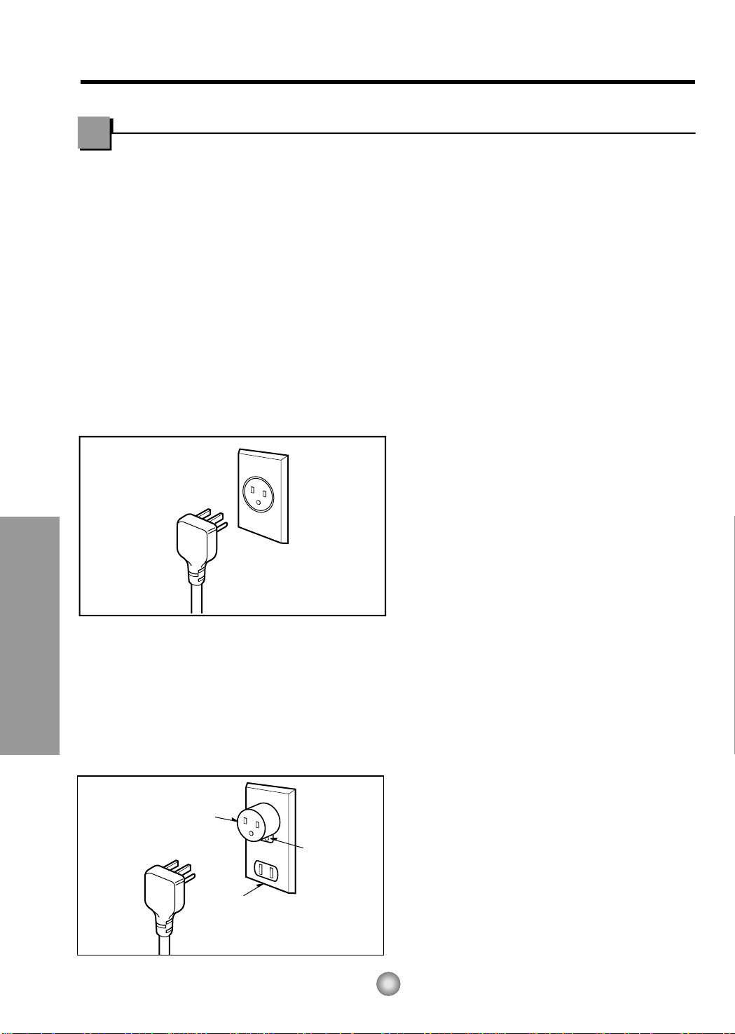
PREFERRED METHOD
Ensure proper ground
exists before use
TEMPORARY METHOD
Adapter plug
Receptacle cover
Metal screw
16
Electrical Safety (Applies to USA only)
Features and Installation
IMPORTANT
(PLEASE READ CAREFULLY)
FOR THE USER'S PERSONAL SAFETY, THIS
APPLIANCE MUST BE PROPERLY GROUNDED
The power cord of this appliance is equipped with a
three-prong (grounding) plug. Use this with a
standard three-slot (grounding) wall power outlet
(Fig. 16) to minimize the hazard of electric shock.
The customer should have the wall receptacle and
circuit checked by a qualified electrician to make
sure the receptacle is properly grounded.
DO NOT CUT OR REMOVE THE THIRD
(GROUND) PRONG FROM THE POWER
PLUG.
A. SITUATIONS WHERE THE APPLIANCE
WILL BE DISCONNECTED ONLY
OCCASIONALLY:
Because of potential safety hazards, we strongly
discourage the use of an adapter plug. However, if
you wish to use an adapter, a TEMPORARY
CONNECTION may be made. Use UL-listed
adapter, available from most local hardware stores
(Fig. 17). The large slot in the adapter must be
aligned with the large slot in the receptacle to
assure a proper polarity connection.
CAUTION: Attaching the adapter ground terminal to
the wall receptacle cover screw does not ground the
appliance unless the cover screw is metal, and not
insulated, and the wall receptacle is grounded
through the house wiring.
The customer should have the circuit checked by a
qualified electrician to make sure the
receptacle is properly grounded.
Disconnect the power cord from the adapter, using
one hand on each. Otherwise, the adapter ground
terminal might break. DO NOT USE the appliance
with a broken adapter plug.
B. SITUATIONS WHERE THE APPLIANCE
WILL BE DISCONNECTED OFTEN.
Do not use an adapter plug in these situations.
Unplugging the power cord frequently can lead to
an eventual breakage of the ground terminal. The
wall power outlet should be replaced by a three-slot
(grounding) outlet instead.
USE OF EXTENSION CORDS
Because of potential safety hazards, we strongly
discourage the use of an extension cord. However,
if you wish to use an extension cord, use a CSA
certified/UL-listed 3-wire (grounding) extension
cord, rated 15A, 125V.
Fig. 16
Fig. 17
17
Before you call for service...
Before you call for service...
Troubleshooting Tips save time and money!
Review the chart below first and you may not need to call for service.
Problem Possible Causes What To Do
■ The air conditioner is
unplugged.
■ The fuse is blown/circuit
breaker is tripped.
■ Power failure.
■ Airflow is restricted.
■ The THERMOSTAT may
not be set high enough.
■ The air filter is dirty.
■ The room may have been
hot.
■ Cold air is escaping.
■ Cooling coils have iced up.
■ Ice blocks the air flow and
stops the air conditioner
from cooling the room.
• Make sure the air conditioner plug is pushed
completely into the outlet.
• Check the house fuse/circuit breaker box and
replace the fuse or reset the breaker.
• If power failure occurs, turn the mode control to OFF.
When power is restored, wait 3 minutes to restart the
air conditioner to prevent tripping of the compressor
overload.
• Make sure there are no curtains, blinds, or furniture
blocking the front of the air conditioner.
• Turn the knob to a higher number. The highest
setting provides maximum cooling.
• Clean the filter at least every 2 weeks.
See the operating instructions section.
• When the air conditioner is first turned on
you need to allow time for the room to cool down.
• Check for open furnace floor registers
and cold air returns.
• Set the air conditioner's vent to the closed position.
• See Air Conditioner Freezes Up below.
• Set the mode control at Med Fan or High Cool with
the thermostat at 1 or 2.
Air conditioner
does not start
Air conditioner
does not cool as it
should
Air conditioner
freezes up
Normal Operation
• You may hear a pinging noise caused by water being picked up and thrown against the condenser
on rainy days or when the humidity is high. This design feature helps remove moisture and improve
efficiency.
• You may hear the thermostat click when the compressor cycles on and off.
• Water will collect in the base pan during high humidity or on rainy days. The water may overflow
and drip from the outdoor side of the unit.
• The fan may run even when the compressor does not.
Abnormal Operation
Loading...