


 Loading...
Service Source
Power Mac G5
Power Mac G5, Power Mac G5 (June 2004), Power Mac G5 (Early 2005)
Updated: 20 June 2006
© 2005 Apple Computer, Inc. All rights reserved.

Power Mac G5
Contents
Basics
Overview 11
Serial Number Location 13
Features |
14 |
|
Overview 14 |
|
|
DDR Memory |
15 |
|
Video |
16 |
|
Fan Controller |
17 |
|
Optical Audio |
17 |
|
Wireless 17 |
|
|
Ports |
18 |
|
Take Apart
General Information 21
Orientation 21
Tools 21
Parts Requiring Enclosure Replacement 21
Take Apart Procedures |
22 |
Opening the Computer |
23 |
Serial ATA Hard Drive |
27 |
Serial ATA Hard Drive Data Cable 30
Optical Drive 35
Front Inlet Fan(s) 40

Memory (DIMMs) 44
AGP/PCI Card 47 AirPort Extreme Card 51 Battery 53
PCI Card Guide 55 Speaker/Fan Assembly 57
Modem: Power Mac G5, Power Mac G5 (June 2004 Dual 1.8 GHz) 60
Soft Modem: Power Mac G5 (June 2004 Dual 2.0/2.5 GHz), Power Mac G5 (Early 2005) 62
Bluetooth Card 64
Heatsink Cover: Power Mac G5 66
Heatsink Cover: Power Mac G5 (June 2004/Early 2005) 68
Processor: Power Mac G5, Power Mac G5 (June 2004 Dual 1.8/2.0 GHz), Power Mac G5 (Early 2005 Dual 2.0/2.3 GHz) 72
Processor: Power Mac G5 (June 2004 Dual 2.5GHz), Power Mac G5 (Early 2005 Dual 2.7GHz) 79
Heatsink Cable: Power Mac G5 (June 2004 Dual 2.5 GHz and Early 2005 2.7 GHz) 86
Rear Exhaust Fans 88
Modem Filter Board and Cables: Power Mac G5 92 Antenna Board and Cables: Power Mac G5 96 Front Panel Board Cable 99
Power Supply: Power Mac G5, Power Mac G5 (June 2004 Dual 1.8/2.0 GHz), Power Mac G5 (Early 2005 Dual 2.0/2.3 GHz) 101

Power Supply: Power Mac G5 (June 2004 Dual 2.5 GHz and Early 2005 Dual 2.7 GHz) 105
Media Bay Sensor Board 109
Air Deflector Sensor Board 112
Air Deflector Sensor Label 114
Logic Board: Power Mac G5 116
Logic Board: Power Mac G5 (June 2004/Early 2005) 126
Modem Filter Board and Cables: Power Mac G5 (June 2004/Early 2005) 135 Antenna Board and Cables: Power Mac G5 (June 2004/Early 2005) 140 PCI Divider: Power Mac G5 143
PCI Divider: Power Mac G5 (June 2004/Early 2005) 147
Thermistor Cable: Power Mac G5, Power Mac G5 (June 2004 Dual 1.8 GHz) 152
Ambient Board: Power Mac G5 (June 2004 Dual 2.0/2.5 GHz), Power Mac G5 (Early 2005 Dual 2.3/2.7 GHz) 154
Front Inlet Fan Cable 158
Front Panel Board 160 Power Button 165

Troubleshooting
General Information 171
Liquid Cooling System (LCS) 171
DDR Memory 172
PCI and AGP Cards 173
Block Diagram 175
Thermal Calibration 176
Resetting the PMU on the Logic Board 176
Power-On Self Test:RAM and Processor Verification 177
Front Panel Board Troubleshooting 177
Power Supply Verification 178
Pinouts 179
Symptom Charts 183
How to Use the Symptom Charts 183
Startup Failures 183
Startup Failures for Power Mac G5 (June 2004 Dual 2.5 GHz/Early 2005 Dual 2.7 GHz) 188
Fans |
190 |
Other Failures |
191 |
Upgrades
Modem Upgrade Kit 195
Bluetooth Upgrade Kit 199

Views
Exploded Views, Power Mac G5 203
Exploded View 1 203
Exploded View #2 204
Exploded Views, Power Mac G5 (June 2004 Dual 1.8/2.0 GHz) |
205 |
||
Exploded View 1 |
205 |
|
|
Exploded View #2 |
206 |
|
|
Exploded Views, Power Mac G5 (June 2004 Dual 2.5 GHz) |
207 |
|
|
Exploded View 1 |
207 |
|
|
Exploded View #2 |
208 |
|
|
Exploded Views, Power Mac G5 (Early 2005 Dual 2.0/2.3 GHz) |
209 |
||
Exploded View 1 |
209 |
|
|
Exploded View #2 |
210 |
|
|
Exploded Views, Power Mac G5 (Early 2005 Dual 2.7 GHz) |
211 |
||
Exploded View 1 |
211 |
|
|
Exploded View #2 |
212 |
|
|
Screw Matrix 213
Internal Views, Power Mac G5 214
Overview 214
Logic Board, Power Mac G5 215
External Views 216
Front View 216
Rear View 217

Service Source
Basics
Power Mac G5
© 2005 Apple Computer, Inc. All rights reserved.

 Overview
Power Mac G5 is a 64-bit desktop computer powered by the PowerPC G5 processor in unior dual-processor configurations. It offers memory expansion up to 8 GB, front-side bus up to 1.25
GHz, and advanced 64-bit computation, while running existing 32-bit applications natively. The computer also includes serial ATA hard drives, high-end graphics capabilities, and computercontrolled cooling based on four independent zones.
This manual covers the following Power Mac G5 models: original Power Mac G5, Power Mac G5 (June 2004), and Power Mac G5 (Early 2005). The tables on the next page illustrate the main differences between these computers. For complete technical specifications, refer to http://www.info.apple.com/support/applespec.html
Power Mac G5 Basics 11

Original Power Mac G5
Original Uni 1.6 GHz |
Original Uni 1.8 GHz |
Original Dual 1.8GHz |
Original Dual 2.0GHz |
800 MHz front bus |
900 MHz front bus |
900 MHz front bus |
1 GHz front bus |
256 MB DDR333 |
512 MB DDR400 |
512 MB DDR400 |
512 MB DDR400 |
SDRAM, expandable |
SDRAM, expandable |
SDRAM, expandable |
SDRAM, expandable |
to 4 GB |
to 8 GB |
to 8 GB |
to 8 GB |
80 GB Serial ATA drive |
160 GB Serial ATA |
160 GB Serial ATA |
160 GB Serial ATA |
|
drive |
drive |
drive |
SuperDrive |
SuperDrive |
SuperDrive |
SuperDrive |
Three PCI slots |
Three PCI-X slots |
Three PCI-X slots |
Three PCI-X slots |
NVIDIA GeForce FX |
NVIDIA GeForce FX |
NVIDIA GeForce FX |
ATI Radeon 9600 Pro |
5200 Ultra video |
5200 Ultra video |
5200 Ultra video |
video |
450 W power supply |
450 W power supply |
600 W power supply |
600 W power supply |
56K modem |
56K modem |
56K modem |
56K modem |
Power Mac G5 (June 2004)
June 2004 Dual 1.8 GHz |
June 2004 Dual 2.0 GHz |
June 2004 Dual 2.5 GHz |
|
|
(with LCS Heasink) |
900 MHz front bus |
1 GHz front bus |
1.25 GHz front bus |
256 MB DDR400 SDRAM, |
512 MB DDR400 SDRAM, |
512 MB DDR400 SDRAM, |
expandable to 4 GB |
expandable to 8 GB |
expandable to 8 GB |
80 GB Serial ATA drive |
160 GB Serial ATA drive |
160 GB Serial ATA drive |
SuperDrive |
SuperDrive |
SuperDrive |
Three PCI slots |
Three PCI-X slots |
Three PCI-X slots |
NVIDIA GeForce FX 5200 Ultra |
NVIDIA GeForce FX 5200 Ultra |
ATI Radeon 9600 XT video |
video |
video |
|
450 W power supply |
600 W power supply |
600 W power supply |
56K modem |
56K soft modem |
56K soft modem |
Power Mac G5 (Early 2005) |
|
|
Early 2005 Dual 2.0 GHz |
Early 2005 Dual 2.3 GHz |
Early 2005 Dual 2.7 GHz |
|
|
(with LCS Heasink) |
900 MHz front bus |
1 GHz front bus |
1.25 GHz front bus |
512 MB DDR400 SDRAM, |
512 MB DDR400 SDRAM, |
512 MB DDR400 SDRAM, |
expandable to 8 GB |
expandable to 8 GB |
expandable to 8 GB |
160 GB Serial ATA drive |
250 GB Serial ATA drive |
250 GB Serial ATA drive |
SuperDrive |
SuperDrive |
SuperDrive |
Three PCI slots |
Three PCI-X slots |
Three PCI-X slots |
ATI Radeon 9600 video |
ATI Radeon 9600 video |
ATI Radeon 9650 video |
450 W power supply |
450 W power supply |
600 W power supply |
12 Power Mac G5 Basics
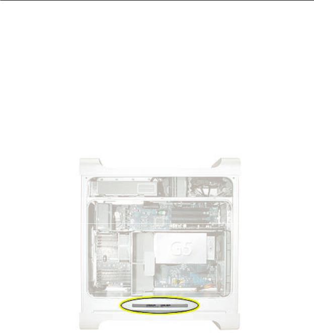
 Serial Number Location
To identify a particular model of Power Mac G5, check the computer’s serial number, which lists the model’s configuration.The serial number is located directly below the air deflector inside the side access panel.
Power Mac G5 Basics 13
 Features
Overview
PowerPC G5 — The Power Mac G5 computer incudes the new 64-bit PowerPC G5 processor running at 1.6, 1.8, 2.0, 2.3, 2.5, or 2.7 GHz, well beyond the speeds of G4 processors.
Serial ATA hard drives — Unlike older parallel drives, the new serial ATA drives in the Power Mac G5 offer up to 150 MB/s data throughput. The 7200 rpm drives come in 80, 160, 250, or 400 GB capacity.
PCI-X slots — Higher-bandwidth PCI slots allow for greater amounts of data when using expansion cards that demand high performance. Both 100 and 133 MHz PCI-X slots are included in higher-end Power Mac G5 computers. For more information, see the “AGP/PCI Card” topic in the Take Apart chapter.
8x AGP bus — This bus provides a higher amount of data transfer to and from the graphics card. Both NVIDIA and ATI graphics cards are offered for the Power Mac G5.
USB 2.0 — All USB ports on the Power Mac G5 support the USB 2.0 standard, which accommodates more high speed peripherals.
Digital audio in and out — The Power Mac G5 introduces two new optical audio (S/PDIF) ports, allowing for optical audio input and output. These ports are in addition to the existing analog sound input and output ports.
Cooling zones — Nine case fans and blowers are logically grouped into four separate cooling zones in the Power Mac G5. Each zone is software-controlled by the system to only cool when necessary, making for a more efficient (and quieter) cooling solution.
ATA/100 bus for optical drives— This technology allows optical storage to read/write data faster.
Double-layer SuperDrives — Power Mac G5 (Early 2005) 16x SuperDrives support double-layer (DVD+R DL) discs. Double-layer discs have two layers of data, allowing the SuperDrive to read and write on either layer, almost doubling the storage to 8.5GB.
Interleaved DDR RAM —The Power Mac G5 requires pairs of DIMMs, which improves performance. Different models require either DDR 333 or DDR 400 RAM. DIMMs must be installed in pairs of equal size and kind. For more information, see the “Memory (DIMMs)” topic in the Take Apart chapter.
Liquid Cooling System — The Power Mac G5 (June 2004 Dual 2.5 GHz and Early 2005 Dual 2.7
14 Power Mac G5 Basics
GHz) models feature a liquid cooling system that is more efficient than a traditional heat sink. This system provides a continuous flow of thermally conductive fluid that transfers heat from the processors.The heated fluid then flows through a radiant grille, where air passing over cooling fins returns the fluid to its original temperature.
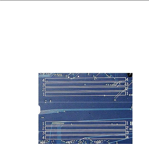
DDR Memory
Depending on the model, Power Mac G5 computers have either four or eight Dual Inline Memory Module (DIMM) slots for Double-Data-Rate (DDR) Synchronous Dynamic Random-Access Memory (SDRAM) devices. The computers ship with a minimum of 256 MB of RAM, installed as a pair of 128 MB DIMMs in two of the DIMM slots. You can install additional DIMMs, provided they are installed in pairs of equal size. A diagram marked on the logic board near the slots illustrates how the pairs must be installed.
To determine the types of DIMMs to install, refer to the table below:
DIMM Slots |
DIMM Speed |
Maximum Amount |
4 (two banks of 2 slots) |
333 MHz, PC 2700 |
up to 4 GB |
8 (two banks of 4 slots) |
400 MHz, PC 3200 |
up to 8 GB |
In addition, DIMMs must fit these specifications:
•2.5 volt
•184-pin module
•Maximum number of memory devices on DDR SDRAM:16
•Nonparity
•Non-error-correcting (NECC)*
*Note: Although they do not take advantage of error-correcting (ECC) RAM features, Power Mac G5 computers can also use ECC memory.
Power Mac G5 Basics 15

Video
The Power Mac G5 computer comes with a graphics card installed in the AGP slot. All graphics cards support dual displays in either extended desktop or video mirroring mode.
The display memory on the AGP card is separate from the main memory. The display memory consists of 64, 128, or 256 MB of DDR video SDRAM. The display memory cannot be expanded by the user.
The following table lists the standard and CTO graphics cards used in Power Mac G5 computers. (Port 1 indicates the connector that is next to the logic board when the card is installed.)
Original G5 Graphics Cards |
Video SDRAM |
Port 2 |
Port 1 |
NVIDIA GeForce FX 5200 Ultra |
64 MB DDR |
DVI |
ADC |
|
|
|
|
ATI Radeon 9600 Pro |
64 MB DDR |
DVI |
ADC |
|
|
|
|
ATI Radeon 9800 Pro |
128 MB DDR |
DVI |
ADC |
NVIDIA GeForce 6800 Ultra DDL* |
256 MB DDR |
dual-link DVI |
dual-link DVI |
|
|
TV out |
TV out |
June 2004 G5 Graphics Cards |
Video SDRAM |
Port 2 |
Port 1 |
|
|
|
|
|
|
NVIDIA GeForce FX 5200 Ultra |
64 MB DDR |
DVI |
ADC |
|
|
|
|
|
|
ATI Radeon 9600 XT |
|
128 MB DDR |
DVI |
ADC |
|
|
|
|
|
ATI Radeon 9800 XT* |
|
256 MB DDR |
DVI |
ADC |
|
|
|
|
|
NVIDIA GeForce 6800 |
GT DDL* |
256 MB DDR |
dual-link DVI |
dual-link DVI |
|
|
|
TV out |
TV out |
NVIDIA GeForce 6800 |
Ultra DDL* |
256 MB DDR |
dual-link DVI |
dual-link DVI |
|
|
|
TV out |
TV out |
Early 2005 G5 Graphics Cards |
Video SDRAM |
Port 2 |
Port 1 |
|
|
|
|
ATI Radeon 9600 |
128 MB DDR |
single-link DVI |
single-link DVI |
|
|
|
TV out |
ATI Radeon 9650 |
256 MB DDR |
dual-link DVI |
single-link DVI |
|
|
|
TV out |
NVIDIA GeForce 6800 Ultra DDL* |
256 MB DDR |
dual-link DVI |
dual-link DVI |
|
|
TV out |
TV out |
ATI Radeon X850 XT |
256 MB DDR |
dual-link DVI |
ADC |
|
|
TV out |
|
* Due to its large size, this card occupies both the AGP slot and the adjacent PCI slot. For this reason, the number of available PCI slots is reduced from three to two.
16 Power Mac G5 Basics

Fan Controller
The Power Mac G5 system employs advanced thermal management to keep acoustic noise to a minimum. The system is divided into discrete zones, each with independently controlled fans bringing in cool air from the front of the enclosure, directing it through ducts and exhausting it
out the rear. Temperature and power consumption are monitored by the operating system, which communicates with the Fan Control Unit, which in turn controls and monitors fan operation. Note that if Mac OS X is not booted, thermal management will not work correctly.
Important: To ensure proper fan and temperature control, you must run Apple Service Diagnostic whenever you replace a processor or logic board with a new processor or logic board. You must also run the diagnostic if you re-install the same processor but in a different connector from the one in which it was originally installed. For more information, see “Thermal Calibration” in the Troubleshooting chapter.
Optical Audio
Digital data is transmitted to and from the optical audio I/O using special optical cables. The 7.5 mm digital optical connectors on the cables, commonly referred to as TOSLink, are for both input and output and conform to the IEC60874-17 connector standard.
The TOSLink friction-lock type F-05 connectors are available from pro-audio, musician’s supply, hifi, and other retailers.
Analog audio signals are converted to digital data internally. All audio is handled digitally inside the computer, including audio data from the CD or DVD drive and from devices connected to the USB and FireWire ports. Audio data is converted to analog form for output to the internal speaker, the headphones, or the analog output port.
Wireless
The Power Mac G5 supports wireless networking with an AirPort Extreme Card and AirPort Extreme Base Station or AirPort Express. AirPort Extreme uses the 802.11g wireless standard to deliver data rates up to 54 Mbps.
The Power Mac G5 also supports an optional internal Apple Bluetooth module. Bluetooth technology enables short-range wireless connections between desktop and laptop computers and other peripheral devices such as cell phones, PDAs, and printers. Support for Bluetooth is built into Mac OS X and compliant with Bluetooth specification v1.1. It operates on a globally available 2.4 GHz frequency band (ISM band) for worldwide compatibility and has a maximum throughput of 1 Mbps.
Important: For proper range and operation, the external Bluetooth antenna and external AirPort antenna must be attached to the Bluetooth and AirPort ports on the back of the Power Mac G5.
Power Mac G5 Basics 17

Ports
The following ports are included on the front and back panels of the Power Mac G5. For illustrations of the port locations, see the “External Views” topic in the Views chapter.
Front
•Power button
•Headphone port
•USB 2.0 port
•FireWire 400 port
Rear
•AirPort antenna port
•Bluetooth antenna port
•Optical audio-out port
•Optical audio-in port
•Audio line-out port
•Audio line-in port
•USB 2.0 ports (two ports)
•FireWire 400 port
•FireWire 800 port
•10/100/1000Base-T Ethernet port
•Modem port
18 Power Mac G5 Basics

Service Source
Take Apart
Power Mac G5
© 2005 Apple Computer, Inc. All rights reserved.

 General Information
Orientation
For most take-apart procedures, it is recommended that you lay the computer on its side before removing or installing the part. For proper operation, however, Apple recommends that the unit be run in the upright position. The computer should never be operated on its side with the access panel facing down.
Tools
The following tools are required to service the computer:
•Long-handled magnetic Phillips screwdriver (10-inch shaft)
•Short-handled magnetic Phillips screwdriver
•Flatblade screwdriver
•Jeweler’s flatblade screwdriver
•Nylon probe tool (black stick 922-5065)
•Needlenose pliers
•Small wire cutter
•Long-handled 2.5 mm hex wrench
•Mat knife and cup hook (to remove locking rivet)
•Tape (for temporarily holding cables out of the way)
•Small mirror (for seeing small boards inside the enclosure)
•Soft cloth (for protect removed parts from scratches)
Parts Requiring Enclosure Replacement
The following are not separate, orderable parts. To replace them, you must replace the enclosure.
•Media blower
•Media fan
•Hard drive locking latches
•Hard drive bay
•Optical drive levers
•Media shelf
•Power harness cable, including hard drive power cables
•Media bay sensor and air deflector sensor cable
•Rear panel latch
Power Mac G5 Take Apart 21

Take Apart Procedures
This manual covers several different Power Mac G5 models. Some models may look slightly different from the one shown in the illustrations; however, except where indicated, the following procedures apply to all models.
22 Power Mac G5 Take Apart

 Opening the Computer
Tools
No tools are required for this procedure.
Preliminary Steps
1.Shut down the computer.
Warning: Always shut down the computer before opening it to avoid damaging its internal components or the components you are installing. Do not open the computer or attempt to install items inside it while it is on.
2.Wait 5 to 10 minutes to allow the computer’s internal components to cool.
Warning: After you shut down the system, the internal components can be very hot. You must let the computer cool down before continuing.
3.Unplug all external cables from the computer except the power cord.
4.Touch the metal PCI access covers on the back of the computer to discharge any static electricity from your body.
Important: Always discharge static before you touch any parts or install any components inside the computer. To avoid generating static electricity, do not walk around the room until you have finished working and closed the computer.
5.Unplug the power cord.
Warning: To avoid damaging its internal components or the components you want to install, always unplug the computer before attempting any take-apart procedure.
6.Put on an ESD wrist strap.
Power Mac G5 Take Apart 23
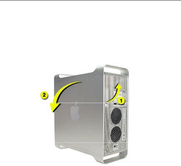
Procedure
1.Hold the side access panel and lift the latch on the back of the computer.
Warning: The edges of the access panel and the enclosure can be sharp. Be very careful when handling them.
2.Remove the access panel and place it on a flat surface covered by a soft, clean cloth.
Replacement Note: Make sure the latch is in the up position before replacing the access panel. If the latch is down, the access panel will not seat correctly in the enclosure.
24 Power Mac G5 Take Apart
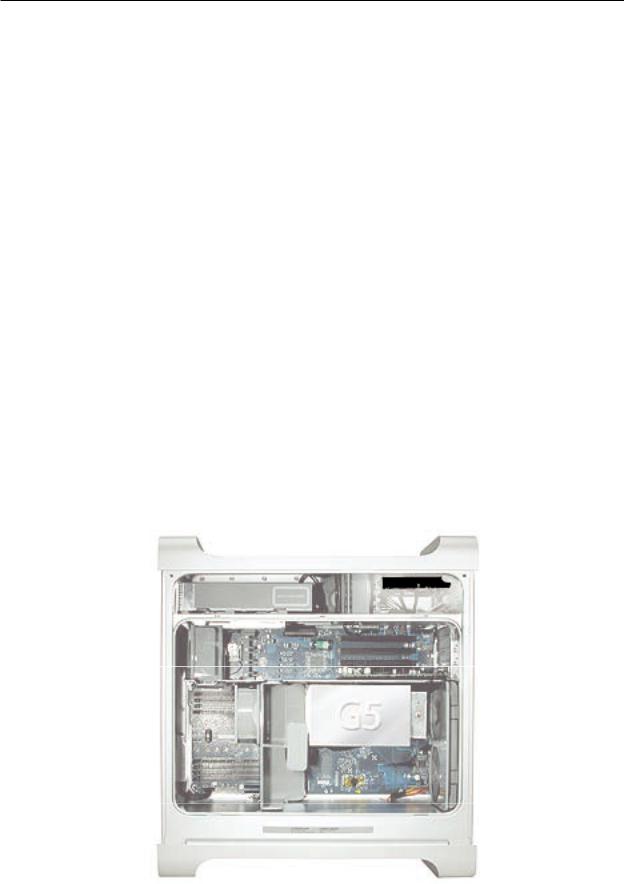
3.Remove the air deflector and place it on a soft, clean cloth.
Replacement Note: To replace the air deflector, insert the three tabs on the bottom edge of the deflector into the three slots in the bottom frame of the enclosure.Then swing the deflector up flush against the top frame of the enclosure.
Important: Make sure you re-install the air deflector before replacing the access panel. If the air deflector is not installed, the computer will not function properly.
Power Mac G5 Take Apart 25
 Serial ATA Hard Drive
The Power Mac G5 computer can accommodate two serial ATA hard drives in its internal hard drive bay. In most configurations, a single hard drive occupies the top portion of the bay.You can install one additional serial ATA hard drive to the empty slot in the bay.
Important: Use the original Apple cables that came with the Power Mac G5 when installing ATA hard drives.
Tools
The only tool required for this procedure is a Phillips screwdriver.
Preliminary Steps
Before you begin, open the computer.
Part Location
Power Mac G5 Take Apart 27
Procedure
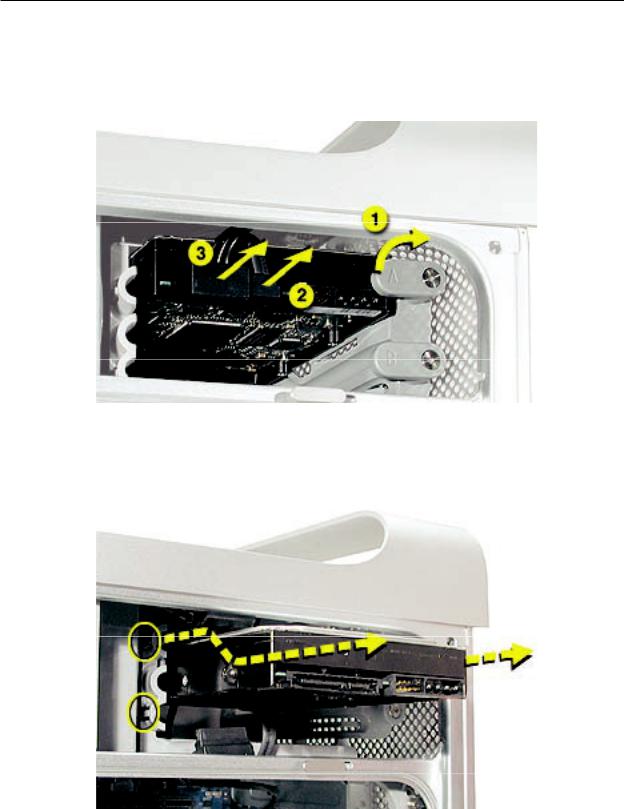
1.Release the drive locking latch by rotating it up.
2.Disconnect the drive data cable and power cable from the hard drive.
3.Pull the drive out of the drive bay, being careful not to touch the bottom of the drive.
Note: If you encounter resistance, use a flatblade screwdriver to release the latches on the drive bay rails as you pull the drive out of the bay. (See circled areas on the illustration below.) If two drives are installed, remove the bottom drive first.
Important: If the printed circuit board (PCB) is exposed on the bottom of the hard drive, hold the drive by its sides. To avoid damaging the replacement drive, take care not to touch the PCB during installation.
28 Power Mac G5 Take Apart
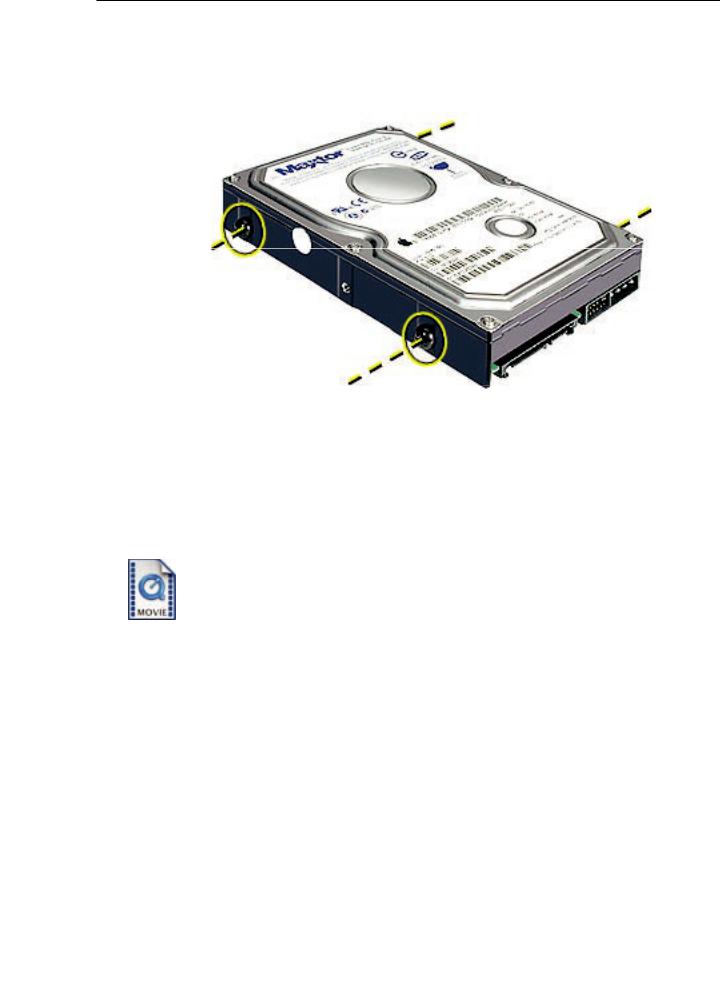
Replacement Note: If you are replacing a hard drive with a new drive, transfer the four guide screws from the sides of the original drive to the new drive. If you are installing an additional drive, transfer the guide screws from the side of the hard drive bay to the drive
Replacement Note: When replacing the top drive, make sure the guide screws align with the middle slot of the drive bay, and then gently push the drive into the bay until it snaps into place.
When installing a bottom drive, align the guide screws with the bottom slot of the drive bay and slide the drive in until it snaps into place.
Power Mac G5 Take Apart 29
Serial ATA Hard Drive Data
Cable
Tools
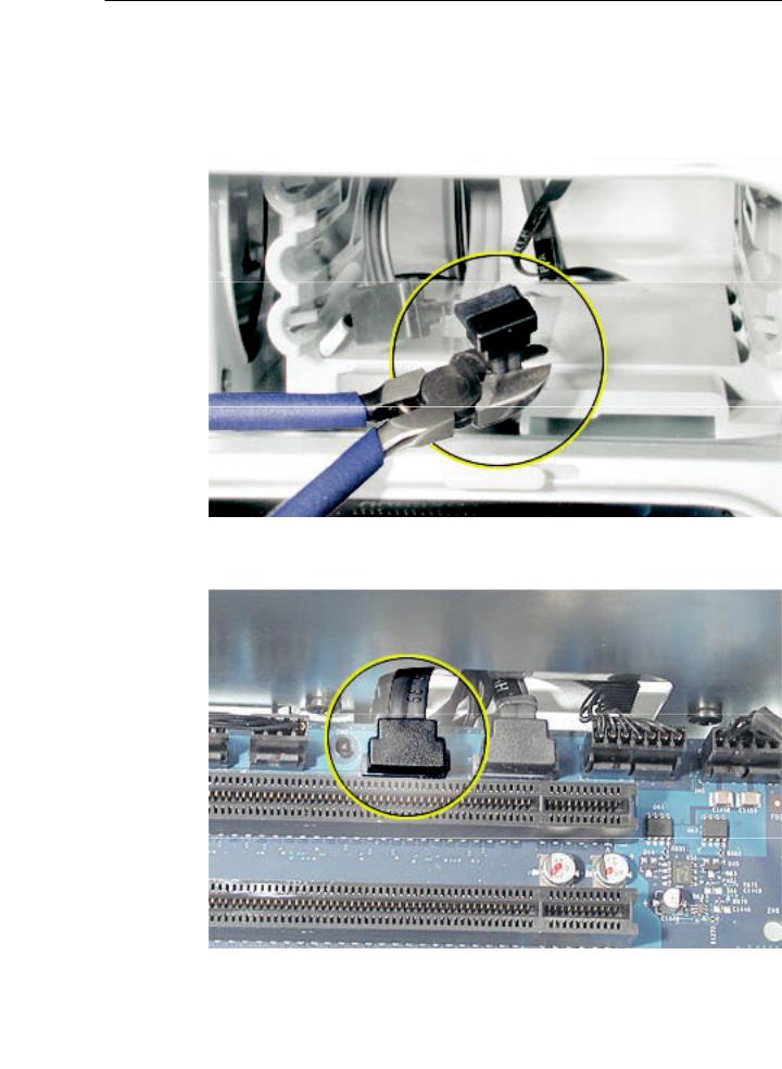
The only tool required for this procedure is a small wire cutter.
Preliminary Steps
Before you begin, open the computer and remove the hard drive(s).
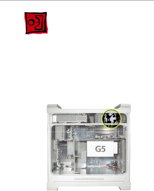
Part Location
30 Power Mac G5 Take Apart

Procedure
Upper Hard Drive Cable
1.Clip off the connector from the hard drive end of the upper hard drive data cable.
2.Disconnect the cable from the logic board, pull the cable out of the hard drive bay, and remove the cable from the enclosure.
Power Mac G5 Take Apart 31
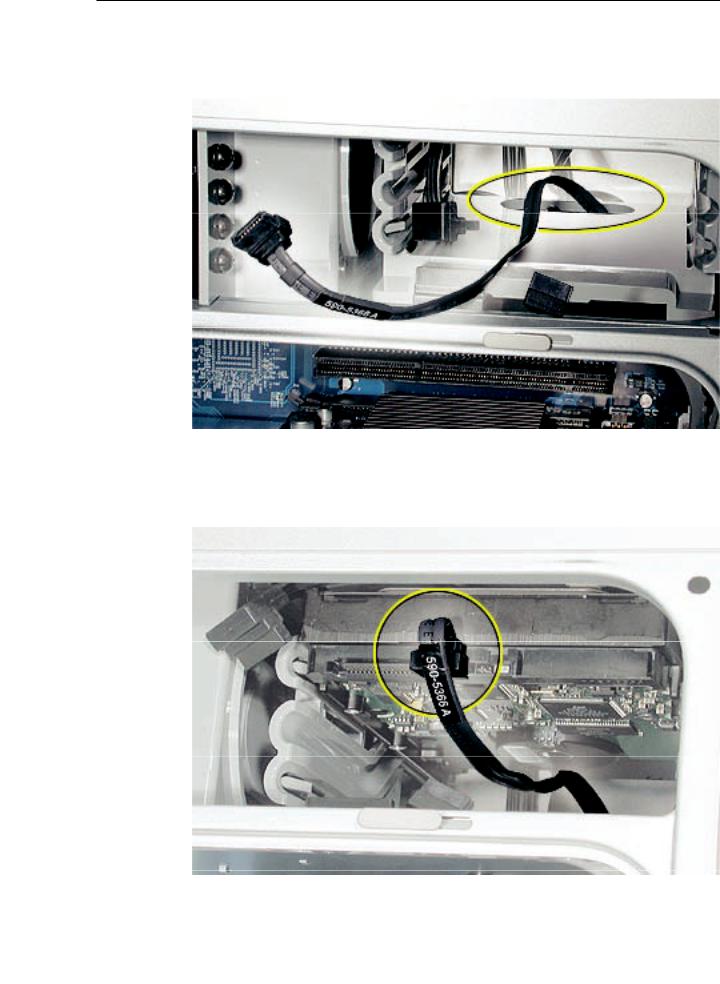
Replacement Note: When installing the replacement upper hard drive cable, first route the cable through the opening in the hard drive bay.
Then install the upper hard drive with the cable routed below the drive, and connect the cable to the drive as illustrated.
32 Power Mac G5 Take Apart
Lower Hard Drive Cable
1.Clip off the connector from the hard drive end of the lower hard drive cable.
2.Disconnect the cable from the logic board, pull the cable out of the hard drive bay, and remove the cable from the enclosure.
Power Mac G5 Take Apart 33

Replacement Note: When installing the replacement lower hard drive cable, first route the cable through the opening in the hard drive bay.
Then install the lower hard drive with the cable routed above the drive, and connect the cable to the drive as illustrated.
34 Power Mac G5 Take Apart
 Optical Drive
Important: When installing a replacement optical drive, use the original Apple cables that came with the Power Mac G5.
Tools
No tools are required for this procedure.
Preliminary Steps
Before you begin, open the computer.
Part Location
Power Mac G5 Take Apart 35
Loading...