


 Loading...
Operating Instructions
Radar sensor for continuous level measurement of bulk solids
VEGAPULS SR 68
Profibus PA
Document ID: 38296
Quick start
|
Quick start |
||||
|
The quick start procedure enables a quick setup with many applica- |
||||
|
tions.You can find further information in the respective chapters of the |
||||
|
operating instructions manual. |
||||
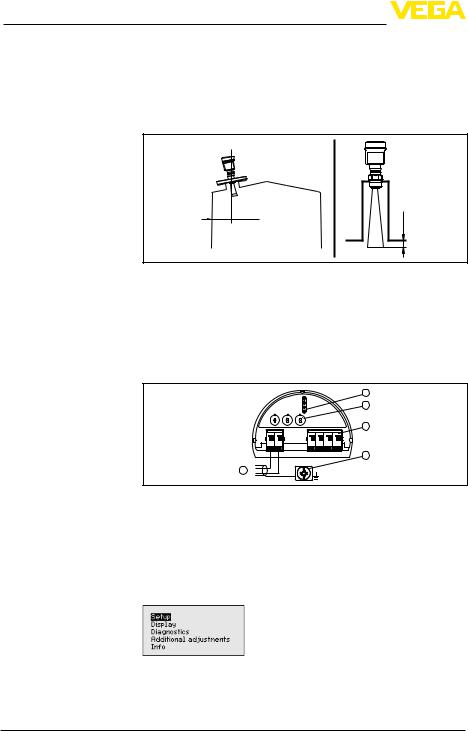
Mounting |
1. Distance from the vessel wall > 200 mm, the antenna should |
||||
|
protrude > 10 mm into the vessel |
||||
|
|
|
|
|
|
|
|
|
|
|
|
|
|
|
|
|
|
200 mm  (7.87")
ca. 10 mm
Electrical connection
Set parameters
2
Fig. 1: Distance of the antenna to the vessel wall/vessel ceiling
2.Note min.socket diameter depending on the socket length
3.Note the instructions for sealing
For further information see chapter "Mounting".
1.Make sure that the power supply corresponds to the specifications on the type label.
2.Connect the instrument according to the following illustration
2
3
|
0 |
1 |
9 |
012 |
9 |
012 |
|
|
|
1 |
8 |
3 |
8 |
|
3 |
4 |
|
Bus |
0 |
|
7 |
7 |
5 |
|||
|
5 |
4 |
6 |
4 |
|
|||
|
|
|
6 |
|
|
|||
(+)1 |
2(-) |
5 6 7 8 |
5 |
1 
Fig. 2: Electronics and connection compartment, single chamber housing
1Voltage supply, signal output
2For display and adjustment module or interface adapter
3Selection switch for bus address
4For external display and adjustment unit
5Ground terminal for connection of the cable screen
For further information see chapter "Connecting to power supply".
1.Go via the display and adjustment module to the menu "Setup".
2.Select in the menu item "Medium" the medium of your application, for example "Powder/Dust".
VEGAPULS SR 68 • Profibus PA
130624-EN-38296

Quick start
3.Select in the menu item "Application" the vessel, the application and the vessel form, for example, silo.
4.Carry out the adjustment in the menu items "Min. adjustment" and "Max. adjustment".
Parameterization example The radar sensor as a distance measuring instrument measures the distance from the sensor to the product surface.For indication of the real level, an allocation of the measured distance to the percentage height must be carried out.
1 m (39.37") |
|
2 |
100% |
||
35 m (1378") |
|
|
0% |
1 |
|
38296-EN-130624
Fig. 3: Parameterization example
1 Min. level max. meas. distance
2 Max. level min. meas. distance
For this adjustment, the distance is entered for min.and max.level. If these values are not known, an adjustment with distances, for example, of 10 % and 90 % is also possible.Starting point for these distance specifications is always the seal surface of the thread or flange.
Further steps |
1. |
In the menu "Additional settings", menu item "Damping" you can |
|
|
adjust the requested damping of the output signal. |
|
2. |
Select the output characteristics in the menu item "Current out- |
|
|
put". |
The quick start is then finished.For further information see chapter "Parameter adjustment".
VEGAPULS SR 68 • Profibus PA |
3 |

Contents
Contents
1 About this document |
6 |
|
1.1 |
Function............................................................................................................................ |
|
1.2 |
Target group...................................................................................................................... |
6 |
1.3 |
Symbolism used............................................................................................................... |
6 |
2 For your safety |
7 |
|
2.1 |
Authorised personnel........................................................................................................ |
|
2.2 |
Appropriate use................................................................................................................ |
7 |
2.3 |
Warning about incorrect use............................................................................................. |
7 |
2.4 |
General safety instructions................................................................................................ |
7 |
2.5 |
CE conformity................................................................................................................... |
8 |
2.6 |
NAMUR recommendations............................................................................................... |
8 |
2.7 |
Radio license for Europe................................................................................................... |
8 |
2.8 |
Radio license for USA/Canada......................................................................................... |
8 |
2.9 |
Environmental instructions................................................................................................ |
9 |
3 Product description |
10 |
|
3.1 |
Configuration.................................................................................................................. |
|
3.2 |
Principle of operation...................................................................................................... |
11 |
3.3 |
Packaging, transport and storage................................................................................... |
11 |
3.4 |
Accessories and replacement parts................................................................................ |
12 |
4 Mounting |
14 |
|
4.1 |
General instructions........................................................................................................ |
|
4.2 |
Mounting preparations - Horn antenna............................................................................ |
14 |
4.3 |
Mounting preparations - Parabolic antenna..................................................................... |
15 |
4.4 |
Mounting instructions...................................................................................................... |
16 |
5 Connecting to power supply |
30 |
|
5.1 |
Preparing the connection................................................................................................ |
|
5.2 |
Connecting..................................................................................................................... |
31 |
5.3 |
Wiring plan, single chamber housing.............................................................................. |
32 |
5.4 |
Wiring plan, double chamber housing............................................................................. |
33 |
5.5 |
Wiring plan, double chamber housing Ex d..................................................................... |
34 |
5.6 |
Wiring plan - version IP 66/IP 68, 1 bar........................................................................... |
36 |
5.7 |
Switch-on phase............................................................................................................. |
36 |
6 Set up with the display and adjustment module |
37 |
|
6.1 |
Insert display and adjustment module............................................................................. |
|
6.2 |
Adjustment system.......................................................................................................... |
38 |
6.3 |
Parameter adjustment..................................................................................................... |
39 |
6.4 |
Saving the parameter adjustment data........................................................................... |
52 |
7 Setup with PACTware |
54 |
|
7.1 |
Connect the PC............................................................................................................... |
|
7.2 |
Parameter adjustment..................................................................................................... |
54 |
7.3 |
Saving the parameter adjustment data........................................................................... |
55 |
8 |
Set up with other systems |
56 |
||
|
8.1 |
DD adjustment programs................................................................................................ |
||
9 |
Diagnosis, Asset Management and service |
57 |
||
|
9.1 |
Maintenance................................................................................................................... |
||
|
|
|
|
|
4 |
|
|
VEGAPULS SR 68 • Profibus PA |
|
130624-EN-38296

38296-EN-130624
|
|
Contents |
9.2 |
Measured value and event memory |
................................................................................ 57 |
9.3 |
Asset Management function........................................................................................... |
58 |
9.4 |
Rectify faults................................................................................................................... |
61 |
9.5 |
Exchanging the electronics module................................................................................ |
64 |
9.6 |
Software update.............................................................................................................. |
64 |
9.7 |
How to proceed in case of repair..................................................................................... |
65 |
10 Dismounting |
|
|
10.1 |
Dismounting steps.......................................................................................................... |
66 |
10.2 |
Disposal.......................................................................................................................... |
66 |
11 Supplement |
|
|
11.1 |
Technical data................................................................................................................. |
67 |
11.2 |
Communication Profibus PA........................................................................................... |
73 |
11.3 |
Dimensions..................................................................................................................... |
77 |
Safety instructions for Ex areas
Please note the Ex-specific safety information for installation and operation in Ex areas.These safety instructions are part of the operating instructions manual and come with the Ex-approved instruments.
Editing status: 2013-05-16
VEGAPULS SR 68 • Profibus PA |
5 |

1 About this document
1 About this document
1.1Function
This operating instructions manual provides all the information you need for mounting, connection and setup as well as important instructions for maintenance and fault rectification.Please read this information before putting the instrument into operation and keep this manual accessible in the immediate vicinity of the device.
1.2Target group
This operating instructions manual is directed to trained specialist personnel.The contents of this manual should be made available to these personnel and put into practice by them.
1.3Symbolism used
•
→
Information, tip, note
This symbol indicates helpful additional information.
Caution: If this warning is ignored, faults or malfunctions can result.
Warning: If this warning is ignored, injury to persons and/or serious damage to the instrument can result.
Danger: If this warning is ignored, serious injury to persons and/or destruction of the instrument can result.
Ex applications
This symbol indicates special instructions for Ex applications.
List
The dot set in front indicates a list with no implied sequence.
Action
This arrow indicates a single action.
1Sequence of actions
Numbers set in front indicate successive steps in a procedure.
Battery disposal
This symbol indicates special information about the disposal of batteries and accumulators.
130624-EN-38296
6 |
VEGAPULS SR 68 • Profibus PA |

38296-EN-130624
2 For your safety
2 For your safety
2.1Authorised personnel
All operations described in this operating instructions manual must be carried out only by trained specialist personnel authorised by the plant operator.
During work on and with the device the required personal protective equipment must always be worn.
2.2Appropriate use
VEGAPULS SR 68 is a sensor for continuous level measurement.
You can find detailed information on the application range in chapter "Product description".
Operational reliability is ensured only if the instrument is properly used according to the specifications in the operating instructions manual as well as possible supplementary instructions.
2.3Warning about incorrect use
Inappropriate or incorrect use of the instrument can give rise to application-specific hazards, e.g.vessel overfill or damage to system components through incorrect mounting or adjustment.
2.4General safety instructions
This is a state-of-the-art instrument complying with all prevailing regulations and guidelines.The instrument must only be operated in a technically flawless and reliable condition.The operator is responsible for the trouble-free operation of the instrument.
During the entire duration of use, the user is obliged to determine the compliance of the necessary occupational safety measures with the current valid rules and regulations and also take note of new regulations.
The safety instructions in this operating instructions manual, the national installation standards as well as the valid safety regulations and accident prevention rules must be observed by the user.
For safety and warranty reasons, any invasive work on the device beyond that described in the operating instructions manual may be carried out only by personnel authorised by the manufacturer.Arbitrary conversions or modifications are explicitly forbidden.
The safety approval markings and safety tips on the device must also be observed.
Depending on the instrument version, the emitting frequencies are in the C or K band range.The low emitting frequencies are far below the internationally approved limit values.When used correctly, there is no danger to health.
VEGAPULS SR 68 • Profibus PA |
7 |

2 For your safety
2.5CE conformity
The device fulfills the legal requirements of the applicable EC guidelines.By affixing the CE marking, we confirm successful testing of the product.
You can find the CE Certificate of Conformity in the download section of our homepage.
Electromagnetic compatibility
Instruments with plastic housing as well as in four-wire or Ex-d-ia version are designed for use in an industrial environment.Nevertheless, electromagnetic interference from electrical conductors and radiated emissions must be taken into account, as is usual with a class A instrument according to EN 61326-1.If the instrument is used in a different environment, the electromagnetic compatibility to other instruments must be ensured by suitable measures.
2.6NAMUR recommendations
NAMUR is the automation technology user association in the process industry in Germany.The published NAMUR recommendations are accepted as the standard in field instrumentation.
The device fulfills the requirements of the following NAMUR recommendations:
•NE 21 – Electromagnetic compatibility of equipment
•NE 43 – Signal level for malfunction information from measuring transducers
•NE 53 – Compatibility of field devices and display/adjustment components
•NE 107 – Self-monitoring and diagnosis of field devices
For further information see www.namur.de.
2.7Radio license for Europe
The instrument is approved according to EN 302372-1/2 (2006-04) for use in closed vessels.
2.8Radio license for USA/Canada
The instrument is in conformity with part 15 of the FCC regulations.
Take note of the following two regulations:
•The instrument must not cause any interfering emissions
•The device must be insensitive to interfering immissions, including those that may cause undesirable operating conditions
Modifications not expressly approved by the manufacturer will lead to expiry of the operating licence according to FCC/IC.
The instrument is in conformity with RSS-210 of the IC regulations.
The instrument may only be used in closed vessels made of metal, concrete, or fibre-reinforced plastic.
8 |
VEGAPULS SR 68 • Profibus PA |
130624-EN-38296

2 For your safety
2.9Environmental instructions
Protection of the environment is one of our most important duties. That is why we have introduced an environment management system with the goal of continuously improving company environmental protection.The environment management system is certified according to DIN EN ISO 14001.
Please help us fulfill this obligation by observing the environmental instructions in this manual:
•
•
Chapter "Packaging, transport and storage" Chapter "Disposal"
38296-EN-130624
VEGAPULS SR 68 • Profibus PA |
9 |
3 Product description
3 Product description
3.1Configuration
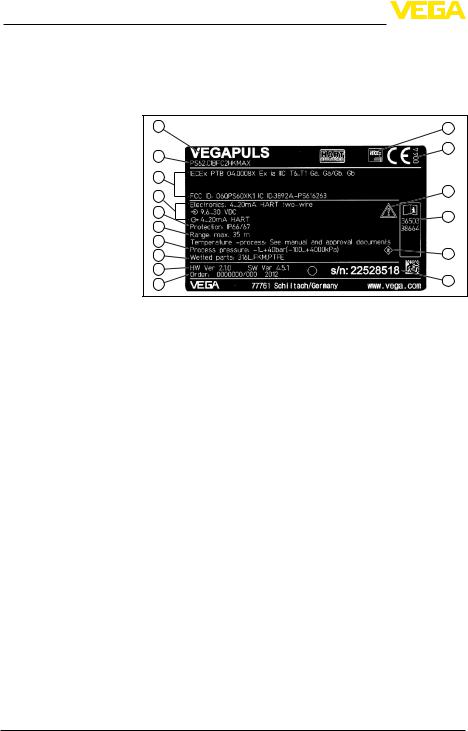
Type plate |
The nameplate contains the most important data for identification and |
|
use of the instrument: |
1 |
16 |
2 |
15 |
|
3
4 |
14 |
|
5 |
13 |
6 |
|
7 |
12 |
|
8 |
||
9 |
11 |
|
10 |
||
|
Fig. 4: Layout of the type label (example)
1Instrument type
2Product code
3Approvals
4Power supply and signal output, electronics
5Protection rating
6Measuring range
7Process and ambient temperature, process pressure
8Material, wetted parts
9Hardware and software version
10Order number
11Serial number of the instrument
12Symbol of the device protection class
13ID numbers, instrument documentation
14Reminder to observe the instrument documentation
15Notified authority for CE marking
16Approval directive
Serial number |
With the serial number of the instrument on the type label you can find |
|
|
the following data on our homepage: |
|
|
• |
Article number of the instrument (HTML) |
|
• |
Delivery date (HTML) |
|
• |
Order-specific instrument features (HTML) |
|
• |
Operating instructions at the time of shipment (PDF) |
|
• |
Order-specific sensor data for an electronics exchange (XML) |
|
• |
Test certificate pressure transmitters (PDF) |
Go to www.vega.com, "VEGA Tools" and "Serial number search".
As an alternative, you can find the data via your Smartphone:
•Download the smartphone app "VEGA Tools" from the "Apple App Store " or the "Google Play Store"
•Scan the Data Matrix code on the type label of the instrument or
•Enter the serial number manually in the app
10 |
VEGAPULS SR 68 • Profibus PA |
130624-EN-38296
38296-EN-130624
|
|
|
|
3 Product description |
|
Scope of this operating |
This operating instructions manual applies to the following instrument |
||||
instructions manual |
versions: |
||||
|
|
• |
Hardware from 2.1.1 |
||
|
|
• |
Software from 4.5.0 |
||
Scope of delivery |
The scope of delivery encompasses: |
||||
|
|
• |
Radar sensor |
||
|
|
• |
Documentation |
||
|
|
–– |
this operating instructions manual |
||
|
|
|
–– |
Test certificate Measurement accuracy, depending on the |
|
|
|
|
–– |
instrumentVEGAPULS SR 68 (optional) |
|
|
|
|
Operating instructions manual "DIsplay and adjustment module |
||
|
|
|
–– |
PLICSCOM" (optional) |
|
|
|
|
Supplementary instructions "GSM/GPRS radio module" |
||
|
|
|
–– |
(optional) |
|
|
|
|
Supplementary instructions manual "Heating for display and |
||
|
|
|
–– |
adjustment module" (optional) |
|
|
|
|
Supplementary instructions manual "Plug connector for con- |
||
|
|
|
–– |
tinuously measuring sensors" (optional) |
|
|
|
|
Ex-specific "Safety instructions" (with Ex versions) |
||
|
|
|
–– |
if necessary, further certificates |
|
|
|
3.2 |
Principle of operation |
||
Application area |
TheVEGAPULS SR 68 is a radar sensor for continuous measurement |
||||
|
|
of bulk solids also under difficult process conditions.It is particularly |
|||
|
|
suitable for level measurement in high silos and large bunkers. |
|||
|
|
The instrument is also suitable for applications in liquids. |
|||
Functional principle |
The antenna of the radar sensor emits short radar pulses with a |
||||
|
|
duration of approx.1 ns.These pulses are reflected by the product |
|||
|
|
and received by the antenna as echoes.The transit time of the radar |
|||
|
|
pulses from emission to reception is proportional to the distance and |
|||
|
|
hence to the level.The determined level is converted into an appropri- |
|||
|
|
ate output signal and outputted as measured value. |
|||
|
|
3.3 Packaging, transport and storage |
|||
Packaging |
Your instrument was protected by packaging during transport.Its |
||||
|
|
capacity to handle normal loads during transport is assured by a test |
|||
|
|
based on ISO 4180. |
|||
|
|
The packaging of standard instruments consists of environment- |
|||
|
|
friendly, recyclable cardboard.For special versions, PE foam or PE |
|||
|
|
foil is also used.Dispose of the packaging material via specialised |
|||
|
|
recycling companies. |
|||
Transport |
Transport must be carried out under consideration of the notes on the |
||||
|
|
transport packaging.Nonobservance of these instructions can cause |
|||
|
|
damage to the device. |
|||
VEGAPULS SR 68 • Profibus PA |
11 |

3 Product description
Transport inspection
Storage
Storage and transport temperature
PLICSCOM
VEGACONNECT
VEGADIS 81
PLICSMOBILE T61
Protective cap
12
The delivery must be checked for completeness and possible transit damage immediately at receipt.Ascertained transit damage or concealed defects must be appropriately dealt with.
Up to the time of installation, the packages must be left closed and stored according to the orientation and storage markings on the outside.
Unless otherwise indicated, the packages must be stored only under the following conditions:
•Not in the open
•Dry and dust free
•Not exposed to corrosive media
•Protected against solar radiation
•Avoiding mechanical shock and vibration
•Storage and transport temperature see chapter "Supplement - Technical data - Ambient conditions"
•Relative humidity 20 … 85 %
3.4Accessories and replacement parts
The display and adjustment module PLICSCOM is used for measured value indication, adjustment and diagnosis.It can be inserted into the sensor or the external display and adjustment unit and removed at any time.
You can find further information in the operating instructions "Display and adjustment module PLICSCOM" (Document-ID 27835).
The interface adapterVEGACONNECT enables the connection of communication-capable instruments to the USB interface of a PC.For parameter adjustment of these instruments, the adjustment software PACTware withVEGA-DTM is required.
You can find further information in the operating instructions "Interface adapter VEGACONNECT" (Document-ID 32628).
TheVEGADIS 81 is an external display and adjustment unit forVEGA plics® sensors.
For sensors with double chamber housing the interface adapter "DISADAPT" is also required forVEGADIS 81.
You can find further information in the operating instructions "VEGADIS 81" (Document-ID 43814).
The PLICSMOBILET61 is an external GSM/GPRS radio unit for transmission of measured values and for remote parameter adjustment of plics® sensors.The adjustment is carried out via PACTware/ DTM by using the integrated USB connection.
You can find further information in the supplementary instructions "PLICSMOBILE T61" (Document-ID 37700).
The protective cover protects the sensor housing against soiling and intense heat from solar radiation.
VEGAPULS SR 68 • Profibus PA
130624-EN-38296

|
|
3 Product description |
|
|
You will find additional information in the supplementary instructions |
|
|
manual "Protective cover" (Document-ID 34296). |
Flanges |
Screwed flanges are available in different versions according to the |
|
|
|
following standards:DIN 2501, EN 1092-1, BS 10, ANSI B 16.5, |
|
|
JIS B 2210-1984, GOST 12821-80. |
|
|
You can find additional information in the supplementary instructions |
|
|
manual "Flanges according to DIN-EN-ASME-JIS" (Document-ID |
|
|
31088). |
Electronics module |
The electronics moduleVEGAPULS series 60 is a replacement part |
|
|
|
for radar sensors ofVEGAPULS series 60.There is a different version |
|
|
available for each type of signal output. |
|
|
You can find further information in the operating instructions "Elec- |
|
|
tronics module VEGAPULS series 60" (Document-ID 36801). |
Antenna impedance cone The antenna impedance cone is used for optimum transmission of microwaves and for sealing against the process.
You find further information in the operating instructions "Antenna impedance cone VEGAPULS 62 and 68" (Document-ID 31381).
38296-EN-130624
VEGAPULS SR 68 • Profibus PA |
13 |

4 Mounting
|
4 |
Mounting |
|
4.1 General instructions |
|
Screwing in |
On instruments with process fitting thread, the hexagon must be tight- |
|
|
ened with a suitable screwdriver.Wrench size see chapter "Dimen- |
|
|
sions". |
|
|
Warning: |
|
|
The housing must not be used to screw the instrument in! Applying |
|
|
tightening force can damage internal parts of the housing. |
|
Protection against mois- |
Protect your instrument further through the following measures |
|
ture |
against moisture penetration: |
|
|
• |
Use the recommended cable (see chapter "Connecting to power |
|
supply") |
|
|
• |
Tighten the cable gland |
|
• |
Loop the connection cable downward in front of the cable gland |
|
This applies particularly to: |
|
|
• |
Outdoor mounting |
|
• |
Installations in areas where high humidity is expected (e.g.through |
|
cleaning processes) |
|
|
• |
Installations on cooled or heated vessels |
Suitability for the process |
Make sure that all parts of the instrument exposed to the process are |
|
conditions |
suitable for the existing process conditions. |
|
These are mainly:
•Active measuring component
•Process fitting
•Process seal
Process conditions are particularly:
•Process pressure
•Process temperature
•Chemical properties of the medium
•Abrasion and mechanical influences
You can find the specifications of the process conditions in chapter "Technical data" as well as on the nameplate.
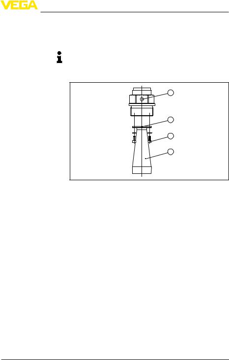
4.2Mounting preparations - Horn antenna
The instrument is also available in versions with an antenna whose diameter is larger than the process fitting (thread, flange).In such cases the antenna must be disconnected from the process fitting before mounting.Proceed as follows:
1.Loosen the hexagon socket screws (3) on the antenna socket with an Allen wrench (size 3)
2.Remove the antenna (4)
Note:
The plastic cone may not be pulled out of the antenna socket.
14 |
VEGAPULS SR 68 • Profibus PA |
130624-EN-38296
4 Mounting
3.Insert the antenna from below into the vessel socket and secure it against falling off
4.Retighten the antenna with hexagon screws to the antenna socket;torque max.2.5 Nm (1.8 lbf ft)
Note:
The radar sensor with rinsing air connection or antenna extension is provided with a notch on the antenna socket.This notch must be aligned with the marking on the process fitting (the marking specifies the position of the polarisation of the radar signal).
1
2
3
4
38296-EN-130624
Fig. 5: Dismounting of the horn antenna
1Marking for the polarisation
2Marking at the antenna socket
3Hexagon screws on the antenna socket
4Antenna
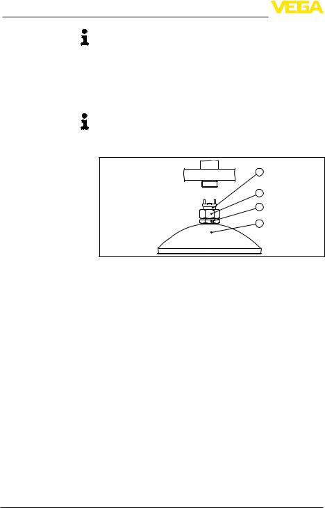
4.3Mounting preparations - Parabolic antenna
The instrument is also available in versions where the antenna has a diameter larger than the process fitting (thread, flange).With such versions the antenna must be disconnected from the process fitting before mounting.Proceed as follows:
1.ClampVEGAPULS SR 68 with the flange, e.g.in a bench vice
2.Hold the connection piece (3) with a wrench on the flat surfaces (width across flats 22 mm)
3.Loosen counter nut (2) completely with a wrench (width across flats 36 mm) in the direction of the antenna
4.Loosen compression nut (1) completely with a wrench (width across flats 41 mm) in the direction of the antenna
5.Remove the parabolic antenna (4) axially
6.Mount sensor flange on the adapter flange and fasten it tightly
7.Check if the O-ring seal is present on the connection piece and make sure it is not damaged.
VEGAPULS SR 68 • Profibus PA |
15 |
4 Mounting
Note:
A damaged O-ring seal must be replaced:FKM (SHS FPM 70C3
GLT), FFKM (Kalrez 6375)
8.Remount the parabolic antenna (4)
9.Fasten compression nut (1) with a wrench (width across flats 41), torque max.50 Nm
10.Fasten counter nut (2) with a wrench (width across flats 36), torque max.40 Nm
Note:
On the version with rinsing air connection, make sure that the holes in the antenna and in the process fitting coincide.This ensures a sufficient air flow (the air is led through the holes to the feed system.A rinsing of the whole parabolic antenna is not intended).
|
|
1 |
|
|
2 |
|
|
3 |
|
|
4 |
|
Fig. 6: Dismounting, parabolic antenna |
|
|
1 |
Connection piece |
|
2 |
Compression nut |
|
3 |
Locknut |
|
4 |
Parabolic antenna |
|
4.4 Mounting instructions |
|
Polarisation |
The emitted radar impulses of the radar sensor are electromagnetic |
|
|
waves.The polarisation is the direction of the electrical wave compo- |
|
|
nent.By turning the instrument in the connection flange or mounting |
|
boss, the polarisation can be used to reduce the effects of false echoes.
The position of the polarisation is marked on the process fitting of the instrument.
130624-EN-38296
16 |
VEGAPULS SR 68 • Profibus PA |

4 Mounting
1 |
2 |
|
Fig. 7: Position of the polarisation |
|
|
1 |
Marking with screwed version |
|
2 |
Marking with flange version |
Installation position |
Mount the sensor at least 200 mm (7.874 in) away from the vessel |
|
|
wall. |
|
200 mm (7.87") 
|
Fig. 8: Mounting of the radar sensor on the vessel top |
|
If you cannot maintain this distance, you should carry out a false |
|
signal storage during setup.This applies particularly if buildup on the |
|
vessel wall is expected.In such a case, it is recommended to repeat |
|
the false signal storage at a later date with existing buildup. |
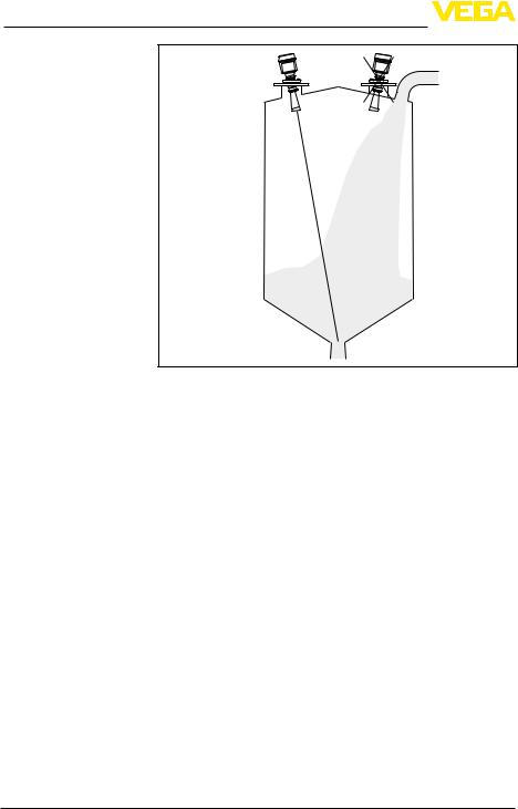
Inflowing medium |
Mounting should not be too close to the inflowing material as the |
|
microwave signal will be interferred.The optimum mounting position is |
|
on the opposite of the filling.To avoid strong pollution, the distance to |
|
the filter or dust extraction must be as big as possible. |
38296-EN-130624
VEGAPULS SR 68 • Profibus PA |
17 |
4 Mounting
Fig.9:Mounting of the radar sensor with inflowing medium
With bulk solids silos with lateral pneumatic filling, mounting should not be in the filling stream as the microwave signal will be interferred. The optimum mounting position is next to the filling.To avoid strong pollution, the distance to the filter or dust extraction must be as big as possible.
130624-EN-38296
18 |
VEGAPULS SR 68 • Profibus PA |

4 Mounting
|
Fig.10:Mounting of the radar sensor with inflowing medium |
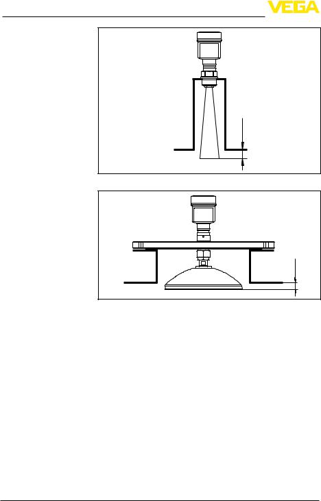
Socket |
The socket piece should be dimensioned in such a way that the |
|
antenna end protrudes slightly out of the socket. |
38296-EN-130624
VEGAPULS SR 68 • Profibus PA |
19 |
4 Mounting
ca. 10 mm
Fig. 11: Recommended socket mounting with horn antenna
10 mm (0.39") |
> |
Fig. 12: Recommended socket mounting with parabolic antenna
When using a swivelling holder, keep in mind that the distance between antenna and socket gets smaller as the inclination of the sensor increases.Additional false reflections may be generated which can influence the measuring result at close range.
130624-EN-38296
20 |
VEGAPULS SR 68 • Profibus PA |
4 Mounting
Fig. 13: Distance between antenna and socket with horn antenna
Fig. 14: Distance between antenna and socket with parabolic antenna
If the medium has good reflective properties,VEGAPULS SR 68 with horn antenna can also be mounted on a longer socket piece. Recommended values for socket heights are specified in the following illustration.You must carry out a false echo storage afterwards.
38296-EN-130624
max. |
h |
d
Fig. 15: Deviating socket dimensions
VEGAPULS SR 68 • Profibus PA |
21 |

4 Mounting
Socket diameter d |
Socket length h |
Recommended anten- |
|
|
na diameter |
40 mm |
100 mm |
40 mm |
50 mm |
150 mm |
48 mm |
80 mm |
250 mm |
75 mm |
100 mm |
500 mm |
95 mm |
150 mm |
800 mm |
95 mm |
Socket diameter d |
Socket length h |
Recommended anten- |
|
|
na diameter |
1½" |
3.9 in |
1½" |
2" |
5.9 in |
2" |
3" |
9.8 in |
3" |
4" |
19.7 in |
4" |
6" |
31.5 in |
4" |
|
|
|
|
Tip: |
|
|
|
|
The instrument is also optionally available with an antenna extension. |
|
|
|
|
The antenna length can be selected (either ex works or later) to allow |
|
|
|
|
the antenna to protrude slightly out of the end of the mounting socket. |
|
|
|
|
Due to the antenna extension however, disturbing reflections are |
|
|
|
|
generated in the close-up range.This can lead to an increase in the |
|
|
|
|
required minimum distance, especially with poorly reflecting media |
|
|
|
|
such as plastic powder.In practice, a cleanly constructed mounting |
|
|
|
|
socket, if necessary with rounded edges, introduces fewer disturbing |
|
|
|
|
influences than an antenna extension. |
Orientation |
|
|
To measure as much of the vessel volume as possible, the sensor |
|
|
|
|
|
should be aligned so that the measuring beam reaches the lowest |
|
|
|
|
level in the vessel.In a cylindrical silo with conical outlet mounting is |
|
|
|
|
carried out on a socket.It should be positioned on one third up to the |
|
|
|
|
half of the vessel radius. |
130624-EN-38296
22 |
VEGAPULS SR 68 • Profibus PA |

4 Mounting
r
1/3r...1/2 r
Fig. 16: Orientation
If mounting in the centre of the silo is not possible, the sensor can be directed to the vessel center by using the optional swivelling holder. The following description shows a simple way to determine the required angle of inclination.
38296-EN-130624
VEGAPULS SR 68 • Profibus PA |
23 |

4 Mounting
α |
d |
a |
Fig. 17: Proposal for installation after orientation VEGAPULS SR 68
The angle of inclination depends on the vessel dimensions.It can be easily checked with a suitable level or water leve on the sensor.
The following chart specifies the distance "a" between installation position and vessel centre dependent on the measuring distance for inclination angles of 2° … 10°.
Distance d |
2° |
4° |
6° |
8° |
10° |
(m) |
|
|
|
|
|
2 |
0.1 |
0.1 |
0.2 |
0.3 |
0.4 |
4 |
0.1 |
0.3 |
0.4 |
0.6 |
0.7 |
6 |
0.2 |
0.4 |
0.6 |
0.8 |
1.1 |
8 |
0.3 |
0.6 |
0.8 |
1.1 |
1.4 |
10 |
0.3 |
0.7 |
1.1 |
1.4 |
1.8 |
15 |
0.5 |
1.0 |
1.6 |
2.1 |
2.6 |
20 |
0.7 |
1.4 |
2.1 |
2.8 |
3.5 |
25 |
0.9 |
1.7 |
2.6 |
3.5 |
4.4 |
30 |
1.0 |
2.1 |
3.2 |
4.2 |
5.3 |
Example:
In a vessel 20 m high, the installation position of the sensor is 1.4 m from the vessel centre.
The necessary angle of inclination of 4° can be read out from this chart.
24 |
VEGAPULS SR 68 • Profibus PA |
130624-EN-38296
4 Mounting
Proceed as follows to adjust the angle of inclination with the swivelling holder:
1. Loosen terminal screw of the swivelling holder with a fork spanner
SW 13
|
|
|
|
2. Direct the sensor, check angle of inclination |
|
|
|
|
Information: |
|
|
|
|
The max.angle of inclination of the swivelling holder is approx.15° |
|
|
|
|
3. Tighten the terminal screw, torque max.20 Nm. |
|
|
|
|
Information: |
|
|
|
|
The hexagon screws must not be loosened. |
Vessel installations |
|
|
The mounting location of the radar sensor should be a place where no |
|
|
|
|
|
other equipment or fixtures cross the path of the microwave signals. |
|
|
|
|
Vessel installations, such as e.g.ladders, limit switches, heating spi- |
|
|
|
|
rals, struts, etc., can cause false echoes and impair the useful echo. |
|
|
|
|
Make sure when planning your measuring site that the radar sensor |
|
|
|
|
has a "clear view" to the measured product. |
|
|
|
|
In case of existing vessel installations, a false echo storage should be |
|
|
|
|
carried out during setup. |
|
|
|
|
If large vessel installations such as struts or supports cause false |
|
|
|
|
echoes, these can be attenuated through supplementary measures. |
|
|
|
|
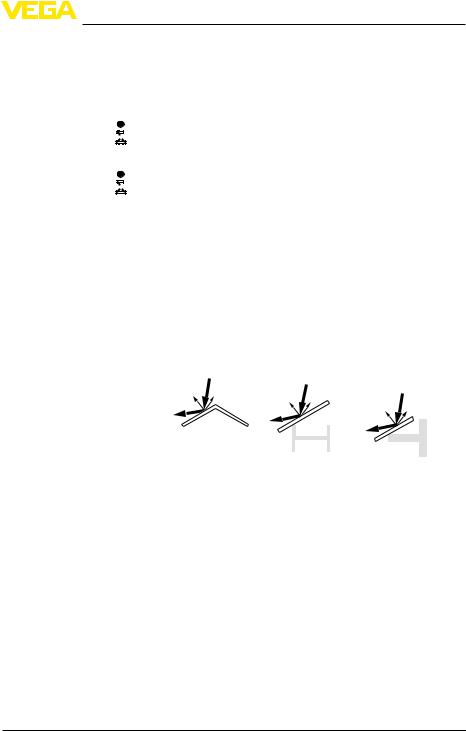
Small, inclined sheet metal baffles above the installations scatter the |
|
|
|
|
radar signals and prevent direct interfering reflections. |
|
|
|
|
|
|
|
|
|
|
|
|
|
|
|
|
|
|
|
|
|
|
|
|
|
|
|
|
|
|
|
|
|
|
|
|
|
|
|
|
|
|
|
|
|
|
|
|
|
|
|
|
|
|
|
|
|
|
|
|
|
|
|
|
|
|
|
|
|
|
|
|
|
Fig.18:Cover smooth profiles with deflectors |
||||||||||
Agitators |
If there are agitators in the vessel, a false signal suppression should |
||||||||||
|
be carried out with the agitators in motion.This ensures that the |
||||||||||
|
interfering reflections from the agitators are saved with the blades in |
||||||||||
|
different positions. |
||||||||||
38296-EN-130624
VEGAPULS SR 68 • Profibus PA |
25 |

4 Mounting
|
Fig. 19: Agitators |
||||||||||
Material heaps |
Large material heaps are detected with several sensors, which can be |
||||||||||
|
mounted on e.g.traverse cranes.For this type of application, it is best |
||||||||||
|
to orient the sensor toward the solid surface.A mutual infuence of the |
||||||||||
|
sensors is not possible. |
||||||||||
|
|
|
|
|
|
|
|
|
|
|
|
|
|
|
|
|
|
|
|
|
|
|
|
|
|
|
|
|
|
|
|
|
|
|
|
|
|
|
|
|
|
|
|
|
|
|
|
Mounting in the vessel insulation
26
Fig. 20: Radar sensors on traverse crane
Information:
Keep in mind that for these applications, the sensors are designed for relatively slow level changes.When usingVEGAPULS SR 68 on a movable bracket, the max.measuring rate must be observed (see chapter "Technical data").
Instruments for a temperature range up to 250 °C or up to 450 °C have a distance piece between process fitting and electronics housing.Ths distance piece is used for thermal decoupling of the electronics against high process temperatures.
Information:
The distance piece must only be incorporated up to max.50 mm in the vessel isolation.Only then, a reliable temperature decoupling is guaranteed.
VEGAPULS SR 68 • Profibus PA
130624-EN-38296

4 Mounting
50 mm (1.97") |
max. |
1
2
3
38296-EN-130624
Installation in subsurface enclosures
Fig. 21: Mounting of the instrument on insulated vessels.
1Electronics housing
2Distance piece
3Vessel insulation
For level measurements in concrete silos, the sensors are often mounted in protective boxes.These boxes can be for example metallic, closed subsurface enclosures.
Mounting in multiple chamber silo
1 |
2 |
Fig. 22: Mounting of the instrument in an subsurface enclosure
1Subsurface enclosure
2Concrete bottom
For this application, the minimal amounts of stray radiation from the sensor can be reflected and strengthened by the walls of the subsurface enclosures.In the case of sensors with plastic housings, this can lead to coupling disturbances.This can be avoided by using a sensor with aluminium or stainless steel housing.
The silo walls of multiple chamber silos are often made of profile walls, such as e.g.profile sheeting, to ensure the required stability.If the radar sensor is mounted very close to a heavily structured vessel wall, considerable false reflections can be generated.Hence the sen-
VEGAPULS SR 68 • Profibus PA |
27 |
Loading...