


 Loading...
Operating Instruction
VEGADIS 371 Ex
16.85 |
VEGADIS 371 Ex
8888

Contents
Contents
Safety information ........................................................................................ |
2 |
1 Product description |
|
|
1.1 |
Function and configuration ................................................................. |
3 |
1.2 |
Types and versions ............................................................................. |
3 |
1.4 |
Dimensions ......................................................................................... |
3 |
1.3 |
Approvals ............................................................................................ |
3 |
1.5 |
Technical data ..................................................................................... |
4 |
2 |
Mounting |
|
|
|
2.1 |
Mounting instructions .......................................................................... |
5 |
3 |
Electrical connection |
|
|
|
3.1 |
Sensor connection .............................................................................. |
6 |
|
3.2 |
Sensor connection Ex-area ................................................................ |
7 |
|
3.3 |
Terminal coordination .......................................................................... |
8 |
|
3.4 |
Ex-separating chamber ....................................................................... |
8 |
4 |
Set-up |
|
|
|
4.1 |
Indicating and adjustment elements ................................................... |
9 |
|
4.2 |
Adjustment ........................................................................................ |
11 |
|
4.3 |
Mounting of the relay modules .......................................................... |
14 |
|
4.4 |
Reset ................................................................................................. |
15 |
5 |
Diagnosis |
|
|
|
5.1 |
Simulation ......................................................................................... |
16 |
|
5.2 |
Fault signals ...................................................................................... |
16 |
Safety information
The described module must only be installed and operated as described in this operating instruction. Please note that other action can cause damage for which VEGA does not take responsibility.
2 |
VEGADIS 371 Ex |
Product description
1 Product description
1.1 Function and configuration
VEGADIS 371 Ex is a digital indicating instrument with integral level switches and current output for panel, surface or rail mounting with LC-display for digital and quasianalogue demonstration.
Max. 4 relays in pairs can be used as relay modules. The modules can be retrofitted. VEGADIS 371 Ex is an indicating instrument and can hence not be adjusted.
The indication is individually scalable between -9999 and 9999. The decimal point can be shifted. The indicated unit can be chosen individually. You can add a lable with the units to the cover.
Configuration
Any sensor can be connected to the meas. circuit of VEGADIS 371 Ex delivering a standardized
4 … 20 mA-signal or a 0 … 10 V-signal.
1.3 Approvals
VEGADIS 371 Ex (appropriate apparatus) is available with the following approval:
Explosion protection - Classification
 II 1G [EEx ia] IIC EC-type approval TÜV 97 ATEX 1174,
- Conformity certificate PTB no. Ex-97.D.2073 X.
For these applications note the appropriate legal documents (EC-type approval and conformity certificate). These are supplied with the instrument.
VEGADIS 371 EX
Ex-relevant technical data are stated in the following attached documents:
EC-type approval TÜV 97 ATEX 1174 Conformity certificate PTB no. Ex-97.D.2073 X
1.2 Types and versions
VEGADIS 371
Digital indicating instrument with integral level switches for front panel mounting or surface mounting.
VEGADIS 371 Ex
Digital indicating instrument with integral level switches for front panel mounting or surface mounting with Exapproval.
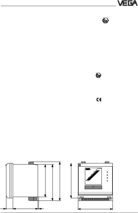
1.4 Dimensions
CE-conformity
VEGADIS 371 Ex meets the protective regulations of EMVG (89/336/EWG) and NSR (72/23/EWG). The conformity has been judged acc. to the following standards:
EMVG Emission |
|
|
|
EN 50 081 - 1: |
|||
1992 |
|
Susceptibility |
EN 50 082 - 2: 1995 |
||||
|
|
||||||
NSR |
EN 60 010 - 1: 1993 |
||||||
|
|
|
|
|
|
|
|
|
|
|
|
|
|
|
|
|
|
|
|
|
|
|
|
92 |
102 |
109 |
96 |
16.85 |
|
|
|
|
VEGADIS 371 EX
19 |
69 |
2 |
96 |
VEGADIS 371 Ex |
3 |

|
|
|
Product description |
1.5 Technical data |
|
||
General |
|
||
Series |
instrument for front panel or wall mounting or |
||
|
|
|
mounting on rail 35 x 7,5 |
Dimensions |
W = 96 mm, H = 104 mm, D = 90 mm |
||
Weight |
approx. 400 g |
||
Housing material |
plastic ABS/POM |
||
Cross section area of conductor |
max. 2,5 mm2 |
||
Ambient conditions |
|
||
|
|
||
Permissible ambient temperature |
-20°C … +60°C |
||
Storage and transport temperature |
-40°C … +85°C |
||
Temperature error |
0,01 %/K |
||
Electrical protective measures |
|
||
|
|
||
Protection class |
II |
||
Overvoltage category |
II |
||
Protection |
|
||
- wall or carrier rail mounting |
IP 20 |
||
- |
front panel mounting |
IP 40 |
|
Voltage supply |
|
||
Supply voltage |
20 … 250 V AC/DC |
||
Power consumption |
4 W, 12,5 VA |
||
Sensor input (floating) |
|
||
|
|
||
Transmission |
analogue |
||
Connection line to the sensor |
2-wire |
||
Iactive |
25 … 15 V (range 4 ... 20 mA) |
||
- |
sensor supply |
||
- |
shortcircuit limitation |
approx. 30 mA |
|
Ipassive |
< 250 Ω (range 4 ... 20 mA) |
||
- |
inner resistance |
||
U |
|
|
> 100 kΩ (range 0 ... 10 V) |
- |
inner resistance |
||
Current output 0/4 … 20 mA (signal circuit, floating)
Resolution |
0,1 % (range 0/4 ... 20 mA) |
max. load |
500 Ω |
Fault signal |
approx. 22 mA |
Linearity error |
0,1 % |
Relay output |
|
Number of relays |
4 (2 modules with 2 relays each) |
Turn-on voltage |
min. 10 mV |
|
max. 250 V AC, 250 V DC |
Switching current |
min. 10 μA |
|
max. 3 A AC, 1 A DC |
Breaking capacity |
max. 54 W DC, 500 VA AC |
Indication of switching condition |
LED lights - relay energized |
|
LED off - relay deenergized |
Digital indication |
|
Zero point (4 mA or 0 V) |
-9999 … 9999 |
Final point (20 mA or 10 V) |
-9999 … 9999 |
Decimal point |
individually selectable |
|
|
4 |
VEGADIS 371 Ex |

Mounting
2 Mounting
2.1 Mounting instructions
VEGADIS 371Ex indicating instrument can be either mounted directly to the wall with three screws, plugged on carrier rail 35 x 7,5 acc. to DIN EN 50 022 or lowered into a front panel. VEGADIS 371Ex must be generally mounted outside hazardous areas.
Before mounting VEGADIS 371 you should adjust the requested sensor signal (Ia, Ip, U). The slide switch on the rear of VEGADIS 371 under the cover is no more accessible after mounting the instrument.
Dependent on the application and the sensor you can choose between active current measurement (Ia), passive current measurement (Ip) or voltage measurement (U). Factory setting "Ia“ see also
"4.2 Adjustment“. The position of the switch also modifies the application conditions for Ex-instruments (VEGADIS 371Ex). Note the type approval or the conformity certificate of VEGADIS 371Ex.
Carrier rail mounting
•Place the adapter plate (A) to the rear of VEGADIS 371 (spring of the adapter plate to the bottom) and tighten the plate with screw B (M4 x 6).
•Place VEGADIS 371 from the bottom to the carrier rail (C) and push the instrument to the top until snap-in.
Wall mounting
•Insert the metal sleeve (D) from top into the housing cut-out.
•Fasten the instrument with three screws (ø max. 4 mm) directly to the wall.
D
Cover 105 

80 Ø4,5*
* DG-hole on instrument
Front panel mounting
•Remove the two pluggable terminal boards (F) and the terminal board (K) to the top.
•Screw the pin (H) to the rear of VEGADIS 371 and tighten with a screwdriver.
•Insert VEGADIS 371 from the front into the front panel (E).
•Push the terminal strap (G) from the back to the pin
(H) and pull with the knurled nut (I) against the front
panel (E).
A B C
E F
G |
H |
I |
92 |
43,5 |
61 |
~90 |
K |
Front panel |
|
cut-out |
|
|
|
VEGADIS 371 Ex |
5 |

Electrical connection
3 Electrical connection
3.1 Sensor connection
Note
Switch off the voltage supply before starting connection work.
Active operation (Ia)1)
4 ... 20 mA
+ 
 -
-
Sensor
Voltage supply
Passive operation (Ip)1)
|
4 ... 20 mA+ |
|
output |
+ - |
- |
Sensor
Signal conditioning instrument VEGAMET
Voltage supply
1)Active or passive operation selectable with slide switch. See “4.1 Indicating and adjustment elements“
6 |
VEGADIS 371 Ex |
Loading...