


 Loading...
Level and Pressure
Operating Instructions
VEGADIF 34 … 51 |
 p
p

Contents
Contents
|
Safety information ......................................................................... |
3 |
|
|
Note Ex-area ................................................................................ |
3 |
|
1 |
Product description |
|
|
|
1.1 |
Function and configuration ................................................... |
4 |
|
1.2 |
Types and versions .............................................................. |
5 |
|
1.3 |
Type plate ............................................................................. |
7 |
|
1.4 |
Technical data ....................................................................... |
8 |
|
1.5 |
Dimensions ......................................................................... |
15 |
|
1.6 |
Approvals ........................................................................... |
20 |
2 |
Mounting |
|
|
|
2.1 |
Verifying operating conditions ........................................... |
21 |
|
2.2 |
Pre-installation ..................................................................... |
22 |
|
2.3 |
Mounting .............................................................................. |
24 |
3 |
Electrical connection |
|
|
|
3.1 |
Connection instructions ...................................................... |
28 |
|
3.2 |
Load resistance .................................................................. |
28 |
|
3.3 |
Connections ........................................................................ |
29 |
|
3.4 |
Ex-applications ................................................................... |
30 |
4 |
Setup |
|
|
|
4.1 |
Adjustment structure .......................................................... |
32 |
|
4.2 |
Adjustment with 4-key adjustment element ....................... |
32 |
|
4.3 |
Adjustment with HART® handheld ...................................... |
38 |
|
4.4 |
Adjustment with PC ............................................................ |
46 |
2 |
VEGADIF 34 … 51 |

Contents
5 Typical installation connections |
|
|
5.1 |
Valves .................................................................................. |
53 |
5.2 |
Impulse lines ....................................................................... |
54 |
5.3 |
Differential pressure measurement ................................... |
55 |
5.4 |
Level measurement ............................................................ |
57 |
5.5 |
Flow measurement ............................................................. |
65 |
6 |
Diagnostics |
|
|
6.1 Failure codes ...................................................................... |
69 |
7 |
Instrument modification ......................................................... |
70 |
Safety information
The described module must only be installed and operated as described in these operating instructions. Please note that other action can cause damage for which VEGA does not take responsibility.
Note Ex-area
Please note the approval documents (yellow binder), and especially the included safety data sheet.
VEGADIF 34 … 51 |
3 |

Product description
1 Product description
1.1 Function and configuration
Function
VEGADIF 34 … 51 differential pressure transmitters are an efficient, modular instrument series for differential pressure, level and flow measurement.
The sensor element of VEGADIF 34 and 44 is a single-chamber ceramic measuring cell. It consists of a disk-shaped ceramic body with ceramic diaphragms on both sides. According to the pressure the diaphragms move and the capacitances change. The difference of the individual capacitances is reciprocally proportional to the difference of the pressures.
The sensor element of VEGADIF 35, 45 and 51 is a silicium plate with pressure sensitive resistors. The differential pressure to be measured is received via separating diaphragms and transmitted to the sensor element via incompressible oil (silicone oil or inert oil). The silicium plate moves according to the differential pressure. The values of the resistors change (piezoresistive principle).
The capacitance or resistance values are detected by the integral electronics and converted into a 4 … 20 mA output signal. This output signal is proportional to the difference of the pressures. Precise digital processing of measured data with maximum resolution ensures excellent technical performance.
The electronics in the pressure transmitter requires a supply voltage of 11.5 … 45 V DC.
The external power supply is provided via a separate supply instrument, e.g.:
-power supply instrument (e.g. VEGASTAB 690)
-processing unit with integral direct voltage source (e.g. active DCS-input)
-VEGAMET series 500 or 600 signal conditioning instrument, VEGALOG 571 processing system or VEGADIS 371 indicating instrument
Configuration
Each VEGADIF consists of only two modular components:
-the electronics housing
-the measuring cell housing.
Sensor specific data are permanently stored in an ASIC in the sensor. Hence the measuring cell modules can be changed, e.g. ceramic for silicium and vice versa. The electronics can be changed, e.g. from 4 … 20 mA standard to
4 … 20 mA with HART®-communication protocol, without dismounting the transmitter.
4 |
VEGADIF 34 … 51 |

Product description
1.2 Types and versions
VEGADIF 34
Measuring cell: ceramic-capacitive
Process connection: acc. to DIN 19 213
Standard application:
Differential pressure and flow measurement with gases, vapours and liquids
VEGADIF 34
VEGADIF 35
Measuring cell:
silicium-piezoresistive with metal separating diaphragms
Process connection: acc. to DIN 19 213
Standard application:
Differential pressure and flow measurement with gases, vapours and liquids, with differential pressure up to 40 bar and static pressures up to 420 bar
VEGADIF 44
Measuring cell: ceramic-capacitive
Process connection: Plus side flange,
minus side acc. to DIN 19 213
Standard application:
Level measurement in pressurized vessels, even with suspended solids, abrasive or high viscosity products
VEGADIF 35
VEGADIF 44
VEGADIF 34 … 51 |
5 |

Product description
VEGADIF 45
Measuring cell:
silicium-piezoresistive with metal separating diaphragm
Process connection: Plus side flange,
minus side acc. to DIN 19 213
Standard application:
Level measurement in pressurized vessels, even with product temperatures up to 400°C
VEGADIF 45
VEGADIF 51
Measuring cell:
silicium-piezoresistive with metal separating diaphragms
Process connection:
Cell isolating diaphragm in standard series, connected via capillary lines
Standard application:
Level, differential pressure and flow measurement especially with high-viscosity products, high temperatures and in food processing industries
For applications in hazardous areas as well as overfill protection acc. to WHG certified instruments are available
VEGADIF 51
6 |
VEGADIF 34 … 51 |

Product description
1.3 Type plate |
Product coding example |
Check before mounting and electrical connec- |
type DIF35AC4E1VH3C |
|
|
||
tion that you are using a suitable differential |
|
|
pressure transmitter. Observe type and cali- |
|
|
bration plate which are located as follows: |
|
|
Calibration plate |
Type plate |
|
|
|
|
Process connection flange 1.4435
Measuring cell seal PTFE 2 ventilation valves,
1 mounting loop Nominal value calibration in mbar/bar
Nom. meas. range 160 mbar, static pressure max. 140 bar LC-indication top
Cable entry Pg 13.5
Configuration of the calibration plate (example)
Cal.
Adj. 0 … 160 MBAR
Calibration range 0 … 160 mbar
Both plates include important data required for mounting and connection. The configuration and contents of the plates are explained in the following example.
Configuration of the type plate (example)
|
VEGA VEGADIF |
Made in |
|
1 |
Germany |
||
Order Code |
DIF35 AC4E1 VH 3C |
||
2 |
Ser.-No. 10612892 |
|
|
|
p -160 … 160 mbar |
|
|
|
Pmax 140 bar |
|
|
|
4…20mA |
U |
11,5 … 45 V DC |
Mat. 1.4571 PTFE
1Basic data of the order no.
2Serial number
VEGADIF 34 … 51 |
7 |

|
|
|
Product description |
1.4 Technical data |
|
||
Mechanical data |
|
||
Materials, wetted parts |
|
||
VEGADIF 34 |
|
||
- |
Diaphragm |
Aluminiumoxideceramic (Al2O3) |
|
- |
Process seal |
FPM, Hastelloy C4 PTFE-plated, EPDM, |
|
|
|
|
FPM for oxygen application, Kalrez |
- |
Process connection |
carbon steel C22.8 chromized 1.0460, |
|
|
|
|
stainless steel 1.4571 or 1.4404, Hastelloy C276 |
|
|
|
2.4819, PVDF (PN 10) |
- |
Ventilation valves |
stainless steel 1.4571 or 1.4404, Hastelloy C276 |
|
|
|
|
2.4819 (only with process connection Hastelloy) |
VEGADIF 35 |
|
||
- |
Separating diaphragms |
stainless steel 1.4401 |
|
- |
Process seal |
FPM, NBR, PTFE, FPM for oxygen |
|
|
|
|
applications |
- |
Process connection |
carbon steel C22.8 chromized 1.0460 |
|
|
|
|
stainless steel 1.4571 or 1.4404, Hastelloy C276 |
|
|
|
2.4819 |
- |
Ventilation valves |
stainless steel 1.4571 or 1.4404, Hastelloy C276 |
|
|
|
|
2.4819 (only with process connection Hastelloy) |
VEGADIF 44 |
|
||
- |
Diaphragm |
Aluminiumoxideceramic (Al2O3) |
|
- |
Process seal |
FPM, Hastelloy C-4 PTFE-plated, EPDM, |
|
|
|
|
FPM for oxygen application, Kalrez |
- |
Process connection (plus side) |
carbon steel C22.8 chromized 1.0460, |
|
|
|
|
stainless steel 1.4571, stainless steel 1.4571 |
|
|
|
PTFE coated |
|
|
|
Hastelloy C276 2.4819 |
- |
Process connection (minus side) |
carbon steel C22.8 chromized 1.0460, |
|
|
|
|
stainless steel 1.4571 or 1.4404, Hastelloy C276 |
|
|
|
2.4819 |
VEGADIF 45 |
|
||
- |
Isolating diaphragm |
stainless steel 1.4435 |
|
- |
Process flange (plus side) |
stainless steel 1.4435 |
|
- |
Process flange (minus side) |
carbon steel C22.8 chromized 1.0460, |
|
|
|
|
stainless steel 1.4571 or 1.4404, Hastelloy C276 |
|
|
|
2.4819 |
VEGADIF 51 |
|
||
- |
Isolating diaphragm |
stainless steel 1.4435 |
|
- |
Process connection |
carbon steel C22.8 chromized 1.0460, |
|
|
|
|
stainless steel 1.4571 or 1.4404, Hastelloy C276 |
|
|
|
2.4819 |
8 |
VEGADIF 34 … 51 |

Product description
Materials, non-wetted parts
Common components |
|
|
- |
Electronics housing and cover |
Al-casting (Cu-free), protective coating 1) |
|
|
Polyester based, colour yellow RAL 1018, |
|
|
black RAL … (cover) |
- |
Type plates |
stainless steel 1.4301 |
- |
O-rings for cover seal |
NBR |
-Screws and nuts
for measuring cell housing or
process connection |
carbon steel C22.8 |
- Mounting loop |
corresponding to process connection |
|
carbon steel C22.8, stainless steel 1.4571 |
VEGADIF 34 |
|
- Fill fluid of the measuring cell |
silicone oil, mineral oil, Voltalef 1 A 2) |
VEGADIF 35 |
|
- Measuring cell housing |
stainless steel 1.4571 |
- Fill fluid of the measuring cell |
silicone oil, Fluorlube 2) |
VEGADIF 44 |
|
- Fill fluid of the measuring cell |
silicone oil, mineral oil, Voltalef 1 A 2) |
VEGADIF 45 and VEGADIF 51 |
|
- Measuring cell housing |
stainless steel 1.4571 |
- Fill fluid of the measuring cell |
silicone oil, vegetable oil, glycerine, high |
|
temperature oil, oil for oxygen applications |
- Capillary line |
stainless steel 1.4571 |
- Fill fluid of the measuring cell |
silicone oil, Fluorlube 2) |
Weights |
|
VEGADIF 34 |
approx. 5 kg |
VEGADIF 35 |
4 … 6 kg, depending on version |
VEGADIF 44 |
8 … 10.5 kg, depending on flange size |
VEGADIF 45 |
6 … 12 kg, depending on flange size and |
|
extension length |
VEGADIF 51 |
4 kg plus capillaries and flange isolating |
|
diaphragm |
Isolating diaphragm |
see tables in "1.5 Dimensions - Isolating |
|
diaphragm" |
1)Sea water resistance (salt spray test acc. to DIN 50 021 passed for 504 h)
2)for applications in pure gases
VEGADIF 34 … 51 |
9 |

|
|
Product description |
Electrical data |
|
|
Connection |
|
|
Cable entry |
Pg 13.5 (for cable-ø 9 … 12 mm) 1) |
|
Screw terminals |
for conductor cross-sections up to 2.5 mm2 |
|
Earth terminal |
for conductor cross-sections up to 4 mm2 |
|
Supply and signal circuit (4 … 20 mA-signal)
Supply voltage |
|
|
- |
not Ex-instruments |
11.5 … 45 V DC |
- |
Ex-instruments |
11.5 … 30 V DC |
Residual ripple |
no influence at USS £ 4.5 V |
|
Output signal |
4 … 20 mA linear (differential pressure proportio |
|
|
|
nal) or square root (flow proportional changeable) |
Resolution |
better than 6 µA |
|
Current limitation |
approx. 23 mA |
|
Measuring range decrease |
2.8 mA (standard) or 4 mA |
|
Measuring range exceed |
20.5 mA acc. to NAMUR |
|
Fault signal (adjustable) |
3.6 mA, 21.5 mA, current value |
|
Integration time 2) |
0 … 16 s with keys on the instrument |
|
|
|
0 … 40 s with HART® handheld |
Adjustment period |
0.5 … 2.0 s depending on measuring range |
|
Raising time |
0.4 … 1.6 s depending on measuring range |
|
Heating time |
2 s |
|
Connection line |
2-wire |
|
Max. permissible load |
depending on supply voltage |
|
|
1560 |
|
|
|
|
in Ohm |
1000 |
|
|
|
|
|
|
|
|
|
|
R total |
500 |
|
|
|
|
Load |
|
|
|
|
|
|
|
|
|
|
|
|
0 |
|
|
|
|
|
11,5 |
20 |
28,5 |
37 |
45 |
Voltage of the external energy UH in Volts
Supply and signal circuit (digital communication signal HART® )
Connection line |
2-wire (the communication must not be influenced |
|
by unshielded cables) |
Line resistance |
£ 25 W/km |
Total resistance |
higher than 250 W (communication resistance of |
|
min. 250 W required) |
Total capacitance |
smaller than 180 nF |
Max. length |
1000 m |
1)with smaller cable diameter a suitable seal must be provided by the customer
2)adjustment time of 10 % … 63 % of the measuring range final value
10 |
VEGADIF 34 … 51 |
Product description
Protective measures
Protection |
IP 65 |
|
IP 68 (option for VEGADIF 35, 45 and 51) |
Protection class |
III |
CE-protective measures 


VEGADIF 34, VEGADIF 35, VEGADIF 44, VEGADIF 45 and VEGADIF 51 differential pressure transmitters meet the protective regulations of EMC (89/336/EWG) and NSR (73/23/EWG). The conformity has been judged acc. to the following standards:
EMC Emission |
EN 50 081 - 1 |
Susceptibility |
EN 50 082 - 2 |
NSR |
EN 61 010 |
NAMUR-regulations
Full compliance with the NAMUR-regulations NE21, May 1993.
Transmission reaction
Measuring ranges
VEGADIF 34 and VEGADIF 44
Features |
Limits |
|
Span |
|
System pressure |
Pressure transmission |
|
Nom. |
|
|
|
|
|
|
liquid |
meas. |
Initial |
Final value |
minimum |
maximum |
Overload |
Overload |
in the sensor |
ranges |
value |
|
|
|
unilateral |
bilateral |
|
|
|
|
|
|
|
|
|
25 mbar |
-25 mbar |
25 mbar |
5 mbar |
25 mbar |
10 bar |
10 bar |
silicone oil 1) |
100 mbar |
-100 mbar |
100 mbar |
5 mbar |
100 mbar |
16 bar 2) |
25 bar 2) |
silicone oil 1) |
500 mbar |
-500 mbar |
500 mbar |
25 mbar |
500 mbar |
100 bar 2) |
140 bar 2) |
mineral oil 1) |
3000 mbar |
-3000 mbar |
3000 mbar |
150 mbar |
3000 mbar |
100 bar 2) |
140 bar 2) |
mineral oil 1) |
VEGADIF 35, VEGADIF 45 and VEGADIF 51
Features |
Limits |
|
Span |
|
System pressure |
Pressure transmission |
|
Nom. |
|
|
|
|
|
|
liquid |
meas. |
Initial |
Final value |
minimum |
maximum |
Overload |
Overload |
in the sensor |
ranges |
value |
|
|
|
unilateral |
bilateral |
|
|
|
|
|
|
|
|
|
10 mbar3) |
-10 mbar |
10 mbar |
2 mbar |
10 mbar |
140 bar |
140 bar |
silicone oil 1) |
40 mbar3) |
-40 mbar |
40 mbar |
5 mbar |
40 mbar |
140 bar |
140 bar |
silicone oil 1) |
160 mbar |
-160 mbar |
160 mbar |
10 mbar |
160 mbar |
140 bar |
140 bar |
silicone oil 1) |
1000 mbar |
-1000 mbar |
1000 mbar |
50 mbar |
1000 mbar |
420 bar 4) |
420 bar 4) |
silicone oil 1) |
6000 mbar |
-6000 mbar |
6000 mbar |
300 mbar |
6000 mbar |
420 bar 4) |
420 bar 4) |
silicone oil 1) |
40000 mbar3) |
-40000 mbar |
40000 mbar |
2000 mbar |
40000 mbar |
100 bar |
420 bar 4) |
silicone oil 1) |
Minimum pressure
VEGADIF 34, 35 and 44 |
1 mbar abs |
VEGADIF 45 and 51 |
10 mbar abs |
1)in applications with pure gases Voltalef 1 A
2)10 bar with process connection PVDF for VEGADIF 34; 40 bar with process flange for VEGADIF 44
3)only VEGADIF 35
4)note nominal pressure of the flanges
VEGADIF 34 … 51 |
11 |

|
|
Product description |
Output characteristics |
|
|
Determination of characteristics |
fixed point method acc. to VDI/VDE 2600, sheet 4 |
|
|
|
(corresponds to the limit point adjustment acc. to |
|
|
DIN 16 086) |
Characteristics |
linear (differential pressure proportional), |
|
|
|
changeable to square root (flow proportional) |
Accuracy data 1)
Feature |
Accuracy 2) |
Hysteresis |
Repeatability |
Instrument |
|
|
|
|
|
|
|
VEGADIF 34 |
better than 0.1 % |
VEGADIF 35 |
better than 0.1 % |
VEGADIF 44 |
better than 0.1 % |
VEGADIF 45 |
better than 0.2 % |
VEGADIF 51 |
better than 0.2 % |
better than 0.05 % better than 0.1 % better than 0.05 % better than 0.1 % better than 0.1 %
better than 0.05 % better than 0.1 % better than 0.05 % better than 0.1 % better than 0.1 %
Long-term stability of the zero signal 3) |
better than 0.1%/12 months (VEGADIF 34 and 44) |
|
better than 0.2%/12 months (VEGADIF 35, 45, 51) |
Influence of other actuating variables |
|
Influence of the static pressure |
|
to zero and span |
better than 0.2 %/PN (VEGADIF 34 and 44) |
|
better than 0.2 %/100 bar (VEGADIF 35, 45, 51) |
Electromagnetic compatibility (EMC) |
interference immunity to NAMUR: 30 V/m |
Influence of vibration 5) 6) |
better than ±0.1 % acc. to DIN/IEC 68, part 2 - 6 |
Climatic class |
GPC acc. to DIN 40 040 |
Calibration position |
upright |
Influence of the mounting position |
max. 2 mbar |
Temperature influence |
|
Average temperature influence of the zero signal 3) 4) or the output span
better than 0.02 %/10 K (+10 … +60°C) better than 0.1 %/10 K (-40 … + 10°C a. 60°C…85°C)
1)Similar to DIN 16 086
2)relating to the nominal measuring range with recommended turn-down limit of 20 : 1
3)relating to the nominal measuring range, reference temperature 25°C, with recommended turn-down limit of 20 : 1
4)with VEGADIF 45 and 51 without isolating diaphragm or capillaries, see temperature influence
5)relating to the nominal measuring range
6)with silicium measuring cell measured on 6000 mbar sensor
12 |
VEGADIF 34 … 51 |

Product description
Additional temperature influence 1) with VEGADIF 45: - by isolating diaphragm
Process connection |
effective |
|
|
Temperature coefficient |
||||||
|
|
|
diaphragm-ø |
|
|
[mbar/10 K] |
||||
Flange DN 50 PN 40 acc. to DIN 2501, |
|
|
|
|
|
|
|
|
||
Seal surface acc. to DIN 2526 form D |
46 mm |
|
|
5.0 |
|
|
||||
Flange DN 80 PN 40 acc. to DIN 2501, |
|
|
|
|
|
|
|
|
||
Seal surface acc. to DIN 2526 form D |
70 mm |
|
|
3.0 |
|
|
||||
Flange DN 80 PN 40 with extension 50 mm |
70 mm |
|
|
3.0 |
|
|
||||
Flange DN 80 PN 40 with extension 100 mm |
70 mm |
|
|
3.0 |
|
|
||||
Flange DN 80 PN 40 with extension 150 mm |
70 mm |
|
|
3.0 |
|
|
||||
Flange DN 80 PN 40 with extension 200 mm |
70 mm |
|
|
3.0 |
|
|
||||
Additional temperature influence 1) with VEGADIF 45: |
|
|
|
|
|
|
|
|||
- by isolating diaphragm |
|
|
|
|
|
|
|
|
||
Isolating diaphragm series |
|
|
effective |
|
Temperature coefficient |
|||||
|
|
|
||||||||
|
||||||||||
|
|
|
diaphragm-ø |
|
[mbar/10 K] |
|
||||
|
|
|
|
|
|
|
unilateral |
|
bilateral |
|
Cell DN 50 PN 16/400 |
|
|
46 mm |
|
3.0 |
|
|
0.5 |
||
Cell DN 80 PN 16/400 |
|
|
70 mm |
|
0.7 |
|
|
0.1 |
||
Cell DN 100 PN 16/400 |
|
|
70 mm |
|
0.7 |
|
|
0.1 |
||
Cell 3" class 150/2000 |
|
|
23/ |
4 |
" |
|
0.7 |
|
|
0.1 |
Cell 4" class 150/2000 |
|
|
23/4" |
|
0.7 |
|
|
0.1 |
||
DIN 11 851, nut DN 50 PN 25 |
|
|
46 mm |
|
3.0 |
|
|
0.5 |
||
DIN 11 851, nut DN 65 PN 25 |
|
|
52 mm |
|
1.0 |
|
|
0.2 |
||
DIN 11 851, nut DN 80 PN 25 |
|
|
71.5 mm |
|
0.7 |
|
|
0.1 |
||
DIN 11 851, socket DN 50 PN 25 |
|
|
46 mm |
|
3.0 |
|
|
0.5 |
||
DIN 11 851, socket DN 65 PN 25 |
|
|
52 mm |
|
1.0 |
|
|
0.2 |
||
DIN 11 851, socket DN 80 PN 25 |
|
|
71.5 mm |
|
0.7 |
|
|
0.1 |
||
Clamp 2" PN 25 |
|
|
45 mm |
|
3.0 |
|
|
0.5 |
||
Clamp 3" PN 25 |
|
|
71.5 mm |
|
0.7 |
|
|
0.1 |
||
DRD-flange DN 25 |
|
|
46 mm |
|
1.5 |
|
|
0.25 |
||
- by capillary line 2) per m |
|
|
0.5 mbar/10 K (unilateral) |
|
||||||
|
|
|
|
|
0.12 mbar/10 K (bilateral) |
|
||||
Operating conditions
Product features
Aggregate |
gaseous, vapour, liquid to high viscosity |
Condition |
also abrasive or aggressive with suitable |
|
material selection of wetted parts acc. to |
|
order code |
1)standard values relating to isolating liquid silicone oil
2)both capillary lines are supplied with the same length
VEGADIF 34 … 51 |
13 |

|
|
|
|
|
Product description |
Temperatures |
|
|
|
||
Ambient temperature |
-40°C … +85°C (for indication: -20°C … +85°C) |
||||
Medium temperature |
|
|
|
||
- |
VEGADIF 34 and VEGADIF 44 |
|
|
|
|
|
FPM (Viton, Fluor-caoutchouc) |
-20°C … +85°C |
|
|
|
|
PTFE (Hastelloy C4, from pabs ³ 900 mbar) |
-40°C … +85°C |
|
|
|
|
EPDM |
-40°C … +85°C |
|
|
|
|
FPM (Viton for oxygen, oil and grease free) |
-10°C … +85°C |
|
|
|
|
Kalrez |
-10°C … +85°C |
|
|
|
- |
VEGADIF 35 and minus side VEGADIF 45 |
|
|
||
|
FDM (Viton, Fluor-caoutchouc) |
-20°C … +85°C |
|
|
|
|
NBR |
-20°C … +85°C |
|
|
|
|
PTFE, from pabs ³ 1 mbar |
-40°C … +85°C |
|
|
|
|
FPM (Viton for oxygen, oil and grease free) |
-10°C … +85°C |
|
|
|
- |
Plus side VEGADIF 45 and VEGADIF 51 |
pabs ³ 1 bar |
/ 0.05 bar £ pabs1) < 1 bar |
||
|
Isolating liquid: |
||||
|
- silicone oil |
-40°C … +200°C |
/ |
-40°C … +180°C |
|
|
- vegetable oil |
-10°C … +200°C |
/ |
-10°C … +120°C |
|
|
- glycerine |
+15°C … +200°C |
/ |
––– |
|
|
- high temperature oil |
-10°C … +350°C |
/ |
-10°C … +200°C |
|
|
- oil for oxygen application |
-40°C … +175°C |
/ |
-40°C … +80°C |
|
Storage and transport temperature |
-40°C … +100°C (VEGADIF 34 and 44) |
||||
|
|
|
-50°C … +100°C (VEGADIF 35, 45 and 51) |
||
Ex-technical data CENELEC
General data
Classification mark |
EEx ia IIC T4/T6 |
|||
Intrinsically safe supply and signal circuit |
|
|||
Classification |
EEx ia IIC |
|||
Only for connection to certified, intrinsically |
|
|||
safe circuits with the max. values: |
|
|||
- |
voltage |
UO = 30 V |
||
- |
current |
IK = 300 mA |
||
- |
efficiency |
P = 1 W |
||
Inner effective capacitance |
Cint = 11.2 nF |
|||
Inner effective inductance |
Lint = 0.2 mH |
|||
Ambient conditions |
|
|||
Ambient temperature around the |
|
|||
oscillator |
|
|||
- |
temperature class T6 |
-40°C … +40°C |
||
- |
temperature class T5 |
-40°C … +55°C |
||
- |
temperature class T4 |
-40°C … +85°C |
||
1) at p |
abs |
< 1 bar (vacuum range) the isolating liquid boils already at lower temperatures |
||
|
|
|
|
|
14 |
|
|
|
VEGADIF 34 … 51 |

Product description |
|
|
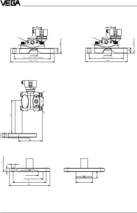
1.5 Dimensions |
|
|
VEGADIF 34 |
|
|
x |
81 |
|
|
|
|
104 |
104 |
View x |
|
|
39 |
80
150 136 |
y |
255
M10 |
View y |
7/16 - 20 UNF |
|
|
Mounting loop |
41,3 |
(optional) |
|
|
1/ " - 18 NPT |
S |
4 |
|
|
Z |
54 |
96 |
|
|
82 |
|
|
M10 |
|
255 |
7/16 - 20 UNF |
PVDF |
|
41,3 |
|
1/4" - 18 NPT
54 |
96 |
82 |
|
with PVDF-flange
VEGADIF 35
235 |
(93)85 |
M10 (M12) |
||
41,3 |
|
- 20 UNF |
||
|
|
7/ |
16 |
|
|
|
|
|
|
|
|
1/ " - 18 NPT |
||
|
|
|
4 |
|
|
|
54 |
|
106 (110) |
|
|
85 |
|
|
|
|
100 (135) |
|
|
The values in brackets relate to PN 420
mbar 500-0 |
5 2 |
|
0 |
VEGADIF 34 … 51 |
15 |
Product description
VEGADIF 44
DIN-flange DN 80/DN 100 |
ANSI-flange 3" |
M10
7/16 - 20 UNF
1/ " - 18 NPT |
4 |
M10 |
7/16 - 20 UNF |
1/ " - 18 NPT |
4 |
VEGADIF 45
M10
7/16 - 20 UNF
1/4" - 18 NPT |
A |
= |
Installation height |
D |
= |
Outer flange diameter |
|
|
b |
= |
Flange thickness |
|
k |
= |
Diameter of hole circle |
|
d2 |
= |
Diameter of hole |
|
d4 |
= |
Seal ledge diameter |
|
d5 |
= |
Extension diameter |
|
RL |
= |
Extension length |
|
dM |
= |
Diaphragm diameter |
d2 |
dM |
L |
d4 |
R |
|
|
|
d5 |
16 |
VEGADIF 34 … 51 |

Product description
Flange connection acc. to DIN 2501, seal ledge acc. to DIN 2526 form D
Order |
Flange |
|
|
|
Holes |
|
Seal ledge |
Dia. |
Extension |
Install. |
||
code |
Size/Nominal pressure |
D |
b |
k |
No. |
d2 |
d4 |
dM |
RL |
d5 |
dM |
height A |
B |
DN 50 / PN 40 |
165 |
20 |
125 |
4 |
18 |
102 |
46 |
–– |
–– |
–– |
360 |
C |
DN 80 / PN 40 |
200 |
24 |
160 |
8 |
22 |
138 |
70 |
–– |
–– |
–– |
360 |
D |
DN 80 / PN 40 |
200 |
24 |
160 |
8 |
22 |
138 |
–– |
50 |
76.5 |
70 |
360 |
E |
DN 80 / PN 40 |
200 |
24 |
160 |
8 |
22 |
138 |
–– |
100 |
76.5 |
70 |
360 |
F |
DN 80 / PN 40 |
200 |
24 |
160 |
8 |
22 |
138 |
–– |
200 |
76.5 |
70 |
360 |
G |
DN 100 / PN 40 |
235 |
26 |
190 |
8 |
26 |
162 |
70 |
–– |
76.5 |
70 |
360 |
|
|
|
|
|
|
|
|
|
|
|
|
|
Flange connection acc. to ANSI B 16.5
Order |
Flange |
|
|
|
|
|
|
|
|
Holes |
|
|
Seal ledge |
|
Dia. |
Extension |
|
Install. |
||||
code |
Size/Nominal press. |
D |
b |
|
|
|
k |
|
No. |
d2 |
|
|
d4 |
|
dM |
|
RL |
d5 |
dM |
|
height |
|
|
in |
lb/sq in |
in/mm |
in/mm |
in/mm |
|
in/mm |
in/mm |
in/mm |
in/mm |
in/mm |
in/mm |
A |
|||||||||
|
|
|
|
|
|
|
|
|
|
|
|
|
|
|
|
|
|
|
|
|
|
|
P |
2 |
/ 150 |
6/152 |
3/ |
4 |
/ |
|
43/ |
/ |
4 |
3/ |
/ |
|
35/ |
/ |
13/ |
/ |
–– |
–– |
–– |
|
14.2/ |
|
|
|
|
|
|
|
4 |
|
|
4 |
|
|
8 |
|
4 |
|
|
|
|
|
|
|
|
|
|
|
19.5 |
120.7 |
|
20 |
|
92 |
|
46 |
|
|
|
|
|
360 |
|||||
R |
3 |
/ 150 |
8.25/ |
15/ |
|
/ |
6/ |
|
4 |
3/ |
/ |
|
5 / |
|
23/ |
/ |
–– |
–– |
–– |
|
14.2/ |
|
|
|
|
|
|
16 |
|
|
|
|
4 |
|
|
|
|
4 |
|
|
|
|
|
|
|
|
|
|
191 |
24 |
|
|
152.4 |
|
20 |
|
127 |
70 |
|
|
|
|
|
360 |
||||
|
|
|
|
|
|
|
|
|
|
|
|
|
|
|
|
|
|
|
|
|
|
|
S |
3 |
/ 150 |
8.25/ |
15/ |
|
/ |
6/ |
|
4 |
3/ |
/ |
|
5/ |
|
–– |
|
2/ |
3/ |
23/ |
/ |
14.2/ |
|
|
|
|
|
|
16 |
|
|
|
|
4 |
|
|
|
|
|
|
|
|
4 |
|
|
|
|
|
|
191 |
24 |
|
|
152.4 |
|
20 |
|
127 |
|
|
50.8 |
76.5 |
70 |
|
360 |
||||
T |
3 |
/ 150 |
8.25/ |
15/ |
|
/ |
6/ |
|
4 |
3/ |
/ |
|
5/ |
|
–– |
|
4/ |
3/ |
23/ |
/ |
14.2/ |
|
|
|
|
|
|
16 |
|
|
|
|
4 |
|
|
|
|
|
|
|
|
4 |
|
|
|
|
|
|
191 |
24 |
|
|
152.4 |
|
20 |
|
127 |
|
|
101.6 |
76.5 |
70 |
|
360 |
||||
|
|
|
|
|
|
|
|
|
|
|
|
|
|
|
|
|
|
|
|
|
|
|
U |
3 |
/ 150 |
8.25/ |
15/ |
|
/ |
6/ |
|
4 |
3/ |
/ |
|
5/ |
|
–– |
|
8/ |
3/ |
23/ |
/ |
14.2/ |
|
|
|
|
|
|
16 |
|
|
|
|
4 |
|
|
|
|
|
|
|
|
4 |
|
|
|
|
|
|
191 |
24 |
|
|
152.4 |
|
20 |
|
127 |
|
|
203.2 |
76.5 |
70 |
|
360 |
||||
|
|
|
|
|
|
|
|
|
|
|
|
|
|
|
|
|
|
|
|
|
|
|
W |
4 |
/ 300 |
10/ |
11/ |
2 |
/ |
78/ |
/ |
8 |
14/ |
16 |
/ |
62/ |
/ |
23/ |
/ |
–– |
–– |
–– |
|
14.2/ |
|
|
|
|
|
|
|
|
9 |
|
|
|
|
9 |
|
4 |
|
|
|
|
|
|
||
|
|
|
254 |
32 |
|
|
200.1 |
|
23 |
|
158 |
70 |
|
|
|
|
|
360 |
||||
VEGADIF 34 … 51 |
17 |

Product description
VEGADIF 51
7/16 - 20 UNF
1/4" -
18 NPT
Isolating diaphragm as cell version, AA … CR
dM
acc. to DIN 2501
Order |
Socket |
Cell |
|
|
|
|
Min. mounting |
Max. |
Weight |
code |
Size/Nominal pressure |
D |
|
b |
|
dM |
distance A |
pressure |
approx. |
|
|
||||||||
|
|||||||||
|
|
|
|
|
|
|
|
|
|
AA |
DN 50 PN 16 |
102 |
|
20 |
|
46 |
130 |
400 bar |
2.6 kg |
AK |
DN 80 PN 16 |
138 |
|
20 |
|
70 |
130 |
400 bar |
4.6 kg |
AM |
DN 80 PN 16 PTFE |
138 |
|
20 |
|
70 |
130 |
400 bar |
4.6 kg |
AN |
DN 80 PN 16 Hastelloy |
138 |
|
20 |
|
70 |
130 |
400 bar |
4.6 kg |
AR |
DN 100 PN 16 |
158 |
|
20 |
|
70 |
130 |
400 bar |
6.2 kg |
|
|
|
|
|
|
|
|
|
|
acc. to ANSI 16.5
Order |
Socket |
Cell |
|
|
|
|
|
|
|
Min. mounting |
Max. |
Weight |
||
code |
Size/Nom. pr. |
D |
|
|
b |
|
|
dM |
|
|
distance |
pressure |
approx. |
|
|
|
|
|
|
|
|||||||||
|
in / lb sq in |
in/mm |
in/mm |
in/mm |
A in/mm |
lb/sq in |
|
|||||||
|
|
|
|
|
|
|
|
|
|
|
|
|
|
|
CK |
3 / 150 |
71/ |
2 |
/ 134 |
3/ |
4 |
/ 20 |
23/ |
4 |
/ 70 |
5 / 130 |
–– |
4.5 kg |
|
CR |
4 / 150 |
81/ |
/ 158 |
3/ |
/ 20 |
23/ |
/ 70 |
5 / 130 |
2500 |
6.2 kg |
||||
4 |
4 |
4 |
||||||||||||
|
|
|
|
|
|
|
|
|
|
|
|
|
|
|
|
|
|
|
|
|
|
|
|
|
|
|
|
|
|
18 |
|
|
|
|
|
|
|
|
|
|
|
|
VEGADIF 34 … 51 |
|

Product description
Isolating diaphragm as cone socket with compression nut, FA … FK
dM
acc. to DIN 11 851
Order |
Socket |
Cell |
|
|
|
|
Compression nut |
|
|
Min. mount. |
Weight |
||
code |
Size/Nominal pr. |
D |
|
f |
|
dM |
G |
|
k |
|
m |
distance A |
approx. |
|
|
|
|
||||||||||
|
|
|
|
|
|
|
|
|
|
|
|
|
|
FA |
DN 50/PN 25 |
68 |
|
11 |
|
46 |
Rd78x1/ " |
22 |
|
19 |
120 |
2.2 kg |
|
FE |
DN 65/PN 25 |
86 |
|
12 |
|
52 |
|
6 |
25 |
|
21 |
120 |
4.0 kg |
|
|
Rd95x1/ " |
|
||||||||||
FK |
DN 80/PN 25 |
100 |
|
12 |
|
71.5 |
|
6 |
29 |
|
25 |
120 |
5.1 kg |
|
|
Rd110x1/ " |
|
||||||||||
|
|
|
|
|
|
|
|
4 |
|
|
|
|
|
Isolating diaphragm as threaded socket, GA … GK
acc. to DIN 11 851
|
|
Order |
Socket |
Threaded socket |
|
Min. mounting |
Weight |
|
|
|
code |
Size/Nominal pres. |
d1 |
G |
dM |
distance A |
approx. |
|
|
GA |
DN 50/PN 25 |
60 |
Rd78/1/ " |
46 |
110 |
1.8 kg |
|
|
GA |
DN 65/PN 25 |
66 |
6 |
52 |
110 |
3.4 kg |
d |
1 |
Rd95x1/ " |
||||||
|
GK |
DN 80/PN 25 |
91 |
6 |
71.5 |
110 |
4.0 kg |
|
d |
M |
Rd110x1/ " |
||||||
|
|
|
|
6 |
|
|
|
|
Isolating diaphragm as Clamp, HA and HK
|
Order |
Socket |
Terminal socket |
Min. mounting |
Weight |
|
|
code |
Size/Nominal pres. |
D |
dM |
distance A |
approx. |
dM |
HA |
DN 2" PN 40 |
64 |
46 |
100 |
1.4 kg |
HK |
DN 3" PN 40 |
91 |
71.5 |
100 |
2.4 kg |
|
Isolating diaphragm as DRD-flange, KE |
|
|
|
|
|
Order |
Socket |
Dimensions |
|
Min. mounting |
Weight |
code |
Nominal pr. |
|
dM |
distance A |
approx. |
A |
PN 25 |
see drawing |
46 |
100 |
1.5 kg |
KE |
|||||
dM |
|
|
|
|
|
˘64 |
|
|
|
|
|
˘84 |
|
|
|
|
|
˘105 |
|
|
|
|
|
VEGADIF 34 … 51 |
|
|
|
|
19 |
Product description
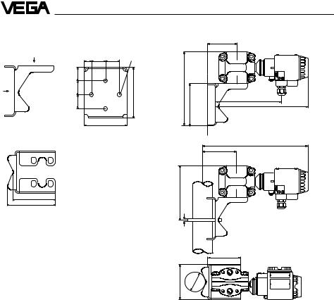
Mounting bracket |
Installation instructions |
|
|
View x |
|
|
|
y |
18 |
35 |
35 |
|
|
|||
|
|
35 |
|
|
x |
|
35 |
|
|
|
|
35 |
|
|
4 holes
ø 10.4 mm
126 |
222 |
126
85
+ Z S
-
~195
~274
106
View y
312,5
105
165
105
119
9
106
98
ø |
60 |
+ Z S
-
1.6 Approvals
For these applications the appropriate official documents (test reports, test certificates and conformity certificates) have to be noted. These are supplied with the appropriate instrument.
Survey on the approvals which are in preparation or for which we applied
Approval |
CENELEC |
CENELEC |
PTB-Zone 0 |
FM |
FM |
WHG |
|
EEx ia IIC |
EEx d IIC |
EEx ia IIC |
Explosion proof |
Intrinsically |
|
Type |
|
|
|
and non incentive |
safe |
|
|
|
|
|
|
|
|
VEGADIF 34 |
• |
• |
• |
• |
• |
• |
|
|
|
|
|
|
|
VEGADIF 35 |
• |
• |
• |
• |
• |
• |
|
|
|
|
|
|
|
VEGADIF 44 |
• |
• |
• |
• |
• |
• |
|
|
|
|
|
|
|
VEGADIF 45 |
• |
• |
• |
• |
• |
• |
|
|
|
|
|
|
|
VEGADIF 51 |
• |
• |
• |
• |
• |
• |
|
|
|
|
|
|
|
|
|
|
|
|
|
|
20 |
|
|
|
|
|
VEGADIF 34 … 51 |
Mounting
2 Mounting
2.1 Verifying operating conditions
VEGADIF is a rugged transmitter for precise differential pressure, level and flow measurement. The accuracy of the measurement mainly depends on the correct installation and the connection of the impulse lines.
Detailed information for differential pressure measurement in aggressive products as well as further information on wiring and coordination of valves, measuring lines and components is given in the VDI/VDE-regulations 3512 as well as DIN 19 201 and DIN 1952. Further information on level measurement is stated in the VDI/VDE-regulations 3519.
The differential pressure transmitter used must meet the technical and safety requirements of the application. Therefore check from the type plate, calibration plate and order code the following data:
Nominal pressure
The pressure stage rating of VEGADIF must be above the operating pressure of the process.
Ambient temperature
The ambient temperature in the installation place must be in the range of -40°C … +85°C. The surface temperature of the electronics housing must not exceed +85°C. Hence it should be noted that the electronics housing should not be heated to more than +85°C due to radiation by neighbouring instruments or systems. If temperatures below -40°C are expected at the installation, the transmitter should be installed in a temperature isolated and heated protection box. If there is danger that measured product or condensate freezes in the process connection or on the measuring cell, the transmitter must be installed in a warmer place or in a heated protection box for process connections and process seals. Similar measures should be taken to protect the impulse lines.
Medium temperature
The permissible medium temperature depends on the process seal, the measuring cell and the isolating liquid. When VEGADIF 45 or 51 are used, note that the product temperature can differ between plus and minus side.
Moisture
Measuring range
The measuring range is calibrated (factory set) acc. to the order. The pressure values adjusted for zero and span are documented on the calibration plate. The values must cover the application. If an adaptation is necessary, this should be carried out acc. to section
4 Setup.
Materials of wetted parts
The material of the wetted parts must be sufficiently resistant. Use the respective material tables for control. A table is given in the product information to VEGADIF, for more information we recommend the VEGA-resistance lists.
Mount horizontally installed instruments such that the cable entry points to the bottom to avoid moisture ingress. The sensor housing is therefore rotational by approx. 350°. For vertically installed instruments loop the connection lines in a bow pointing to the bottom to the instrument housing, so that rain or condensation water can drain off the cable. This is mainly valid for mounting outside, in humid areas (e.g. by cleaning processes) or on cooled or heated vessels.
VEGADIF 34 … 51 |
21 |

Mounting
2.2 Pre-installation
Selection of the installation location
The selection of a suitable installation location under extreme ambient conditions is needed for
-quality of the measurement
-a long lifetime of the transmitter
-low maintenance expenses.
Note the following regulations:
Installation level
•For level measurements install below the minimum level (the diaphragm or the isolating diaphragm must be completely covered).
•For measurement of gases, install transmitter above the pressure tapping points.
•For the measurement of vapours and liquids, install transmitter below the pressure tapping points.
Mounting locations
•Mount the transmitter as near as possible to the pressure tapping points.
•Keep impulse lines as short as possible.
•Mounting and maintenance work should be carried out without obstruction.
•The transmitter, the tapping points, the impulse lines and the valves should be easily accessible.
•If available, the mounting place should provide a good view to the LC-display.
Ambient influences
•Keep the vibration and shock effect to a minimum.
•Avoid corrosive ambient atmosphere.
•Reduce condensation to a minimum.
Note:
Under arduous ambient conditions, a protective housing is recommended.
Adaptation of the transmitter
For optimum adaptation of your VEGADIF to the installation place the following measures can be carried out:
Rotate the electronics housing
After loosening the locking screw below the electronics housing, the housing can be rotated by approx. 330°. A stop prevents further turning. Hence the terminal compartment can be set to an optimum position for cable entry or the LC-display into an optimum reading position.
Fig. 2.1 Loosen the locking screw
When the best position is reached, tighten the locking screw again.
Fig. 2.2 Fastening of the locking screw
22 |
VEGADIF 34 … 51 |
Loading...