


 Loading...
Level and Pressure
Operating Instructions
VEGAMET 514
%
100
- 

 +
+
ESC |
OK |
|
|
|
CONNECT |
|
CONNECT |
1 |
2 |
1 |
2 |
on  on
on
in |
out |

Contents
Contents
1 |
Product description |
|
|
|
1.1 |
Function and configuration |
................................................ 4 |
|
1.2 |
Approvals ........................................................................... |
5 |
|
1.3 |
Features ............................................................................. |
5 |
|
1.4 |
Technical data .................................................................... |
6 |
|
1.5 |
Dimensions ......................................................................... |
9 |
2 |
Mounting ................................................................................... |
10 |
|
3 |
Electrical connection |
|
|
|
3.1 |
Connection instructions ................................................... |
11 |
3.2Connection instructions for Ex approved
|
|
applications ....................................................................... |
11 |
|
3.3 |
Wiring plan ........................................................................ |
12 |
4 |
Adjustment |
|
|
|
4.1 |
Indicating and adjustment elements ............................... |
13 |
|
4.2 |
Adjustment system .......................................................... |
14 |
|
4.3 |
Adjustment via PC ........................................................... |
15 |
|
4.4 |
Configuration and parameter adjustment ....................... |
16 |
|
4.5 |
Comparison: reduced menu – extended menu .............. |
17 |
5 |
Setup .......................................................................................... |
18 |
|
6 Settings in the "reduced menu" |
|
||
|
6.1 |
Configuration of measurement loop ............................... |
19 |
|
6.2 |
Adjustment with medium .................................................. |
20 |
|
6.3 |
Adjustment without medium ............................................ |
21 |
|
6.4 |
Scaling .............................................................................. |
22 |
|
6.5 |
Integration time ................................................................ |
23 |
|
6.6 |
Output ............................................................................... |
24 |
|
6.7 |
Simulation ......................................................................... |
25 |
|
6.8 |
Password, language, default, reset, menu mode .......... |
26 |
|
|
|
|
2 |
|
|
VEGAMET 514 |

Contents
7 |
Settings in the "extended menu" |
|
|
|
7.1 |
Configuration of measurement loop ............................... |
27 |
|
7.2 |
Tare ................................................................................... |
32 |
|
7.3 |
Monitoring ......................................................................... |
33 |
|
7.4 |
Configuration of inputs ..................................................... |
34 |
|
7.5 |
Configuration of outputs .................................................. |
35 |
|
7.6 |
Adjustment........................................................................ |
37 |
|
7.7 |
Conditioning ...................................................................... |
38 |
|
7.8 |
Parameter adjustment of outputs ................................... |
39 |
|
7.9 |
Simulation ......................................................................... |
44 |
|
7.11 |
Password, language, menu mode .................................. |
44 |
|
7.10 |
Special function: Reset .................................................... |
44 |
|
7.12 |
Special function: Manual correction ................................ |
45 |
|
7.13 |
Linearisation curves ........................................................ |
46 |
|
7.14 |
Info .................................................................................... |
49 |
|
7.15 |
Reset VEGAMET ............................................................. |
50 |
8 |
Measured quantity and units ................................................ |
51 |
|
9 |
Diagnostics |
|
|
|
9.1 |
Maintenance ..................................................................... |
52 |
|
9.2 |
Simulation ......................................................................... |
52 |
|
9.3 |
Fault signal........................................................................ |
52 |
|
9.4 |
Repair ............................................................................... |
52 |
|
9.5 |
Error codes ...................................................................... |
53 |
10 |
Menu schematics |
|
|
|
10.1 |
Menu schematic "reduced menu" .................................. |
56 |
|
10.2 |
Menu schematic "extended menu" ................................. |
58 |
|
Safety information ...................................................................... |
64 |
|
|
Note Ex area .............................................................................. |
64 |
|
VEGAMET 514 |
3 |
Product description
1 Product description
1.1 Function and configuration
VEGAMET 514 is a signal conditioning instrument for a number of applications, e.g.:
-level measurement
-gauge measurement
-process pressure measurement
-measurement with automatic correction
-etc.
Function
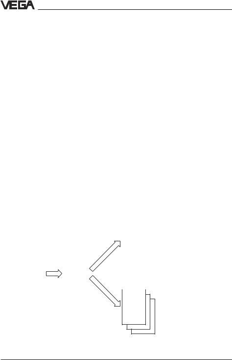
The signal conditioning instruments power the connected sensors and process their analogue measuring data. The conditioning is done via a special software consisting of functional components (FB), input components (EB), output components (AB) as well as DCS components (PB).
Configuration
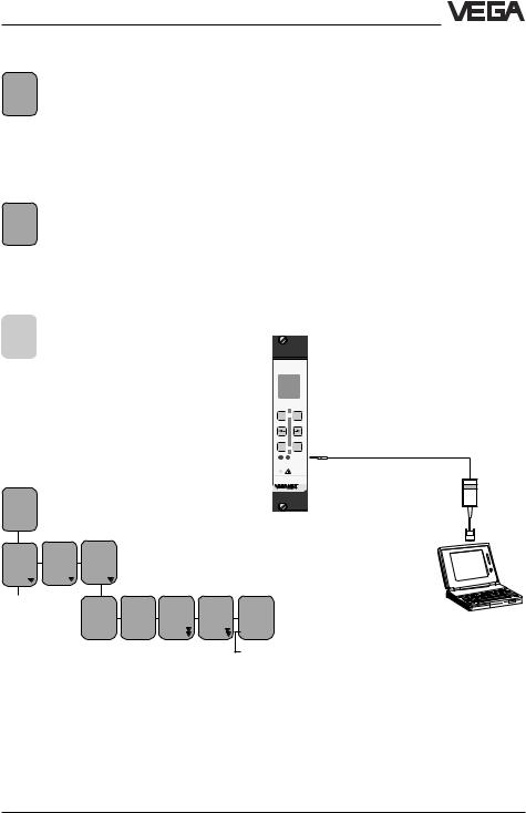
The VEGAMET 514 signal conditioning instrument is constructed as module card in European size with 5 TE (= 25.4 mm) width. The front plate contains an adjustment module with LC display and keys. The front plate of VEGAMET 514 N does not contain an adjustment module.
Software configuration
|
|
|
|
|
|
|
|
|
|
|
|
|
|
|
Output components |
||
|
|
|
|
|
|
|
- |
current output |
|||||||||
|
|
|
|
|
|
|
- |
voltage output |
|||||||||
|
|
|
|
|
|
|
- |
DISBUS outputs |
|||||||||
|
|
|
|
|
|
|
- |
failure output |
|||||||||
Input component |
- |
MET display |
|||||||||||||||
- |
continuous current |
|
|
|
|
|
|
|
- |
relay outputs |
|||||||
|
input |
|
|
|
AB |
|
|
|
|
|
|||||||
|
|
|
|
|
|
|
|
|
|||||||||
- |
contact input |
|
|
|
|
|
|
|
|
||||||||
|
|
|
|||||||||||||||
|
|
|
|
|
|
|
|
|
|
|
|
|
|
|
|
|
|
|
|
|
|
EB |
|
|
FB |
|
|
|
|
|
|
|
|
|
|
|
|
|
|
|
|
|
|
|
|
|
|
|
|
|
|
||
|
|
|
|
|
|
|
|
|
|
|
|
|
|
||||
|
|
|
|
|
|
|
|
||||||||||
|
|
|
|
|
|
|
|
|
|
|
|
|
|
PC/DCS components |
|||
|
|
|
|
|
|
|
|
|
|
|
|
|
|
- PC/DCS outputs |
|||
Functional component |
PB |
|
- measurement loop |
||
|
||
TAG 1 |
|
|
|
|
4 |
VEGAMET 514 |

Product description
1.2 Approvals |
1.3 Features |
VEGAMET are available with the following approvals:
-explosion protection: appropriate operating instrument with intrinsically safe circuit (VEGAMET 514 Ex)
-overfill protection acc. to WHG
For such applications, please note the appropriate official documents (general type approval, test and conformity certificates). They come with the respective instrument
Ex approval
For hazardous areas, certification acc. to CENELEC defined in the conformity certificate PTB no. Ex-95.D.2145 X for VEGAMET 514 Ex.
WHG approval
Signal conditioning instrument as part of an overfill protection system acc. to WHG (test certificate number see table).
-microcomputer-controlled signal conditioning instrument for continuous measurement
-adjustment module with LC display and 6 keys (not with VEGAMET 514 N)
-adjustable integration time
-two fixed and three user-programmable linearisation curves
-fault monitoring
-fault signal and failure diagnosis via display
Inputs:
-1 sensor input (capacitive electrode, pressure transmitter or other 4 … 20 mA sensor)
-1 correction input (for key, switch or level
switch)
Outputs:
-1 current output 0/4 … 20 mA
-1 voltage output 0/2 … 10 V
-2 relay outputs (spdt)
-1 DISBUS output for digital wiring and for connection of VEGADIS 174
-1 fail-safe relay
-adjustment also via PC with adjustment software VVO; connection via the interface adapter of the VEGACONNECT series
Instrument |
Oscillator |
VEGAMET |
Test certificate |
Auxiliary level switch |
|
|
|
no. |
VEGASEL |
|
|
|
|
|
Capacitive electrodes |
E17 EX |
514 EX |
Z-65.13-123 |
543 … 547 |
EL 11 EX0, EL 21 EX0, |
E18 EX |
|
|
643 |
EL 24 EX0, EL 29 EX, |
|
|
|
|
EL 31 EX0, EL 42 EX0 |
|
|
|
|
|
|
|
|
|
Pressure transmitters |
E23, |
514 |
Z-65.11-130 |
543 … 547 |
D80, D81, D84, D86, |
E23 Ex |
514 EX |
|
643 |
D84 EX, D86 EX |
|
|
|
|
|
|
|
|
|
Pressure transmitters |
E22, |
514 |
Z-65.11-130 |
543 … 547 |
D77, D85, D87, |
E22 Ex |
514 Ex |
|
643 |
D77 EX, D85 EX, D87 EX |
|
|
|
|
|
|
|
|
|
VEGAMET 514 |
5 |

Product description
1.4 Technical data
Power supply
Operating voltage |
Unom = 24 V AC (20 … 53 V), 50/60 Hz |
|
|
|
= 24 V DC (20 … 72 V) |
Power consumption |
approx. 6 VA or approx. 4 W |
|
Meas. data input |
|
|
Number |
1 input |
|
Input type |
active two-wire input, analogue (sensor is |
|
|
|
powered by VEGAMET) |
Range |
4 … 20 mA |
|
Sensor |
capacitive electrodes, pressure transmitters, |
|
|
|
process pressure transmitters, differential |
|
|
pressure transmitters |
Voltage |
|
|
- |
at 4 mA |
approx. 18 V DC |
- |
at 20 mA |
approx. 15 V DC |
Current limitation |
at approx. 26 mA, short-circuit-proof |
|
Detection line break |
< 3.6 mA |
|
Detection short-circuit |
> 21 mA |
|
Min. adjustment delta |
2 % of the entered sensor values |
|
Connection cable |
2-wire standard cable (screening |
|
|
|
recommended) |
max. resistance per wire |
35 Ω |
|
Resolution |
1 µA |
|
Linearity error |
0.025 % at 4 … 20 mA |
|
Temperature error |
0.04 %/10 K at 4 … 20 mA |
|
Correction signal input |
|
|
Number |
1 input |
|
Function |
switching signal for triggering corrections |
|
|
|
or special relay modes via |
|
|
external switching contact |
Voltage |
5 V (from instrument) |
|
Current |
5 mA |
|
External cable resistance |
€≤ 150 Ω |
|
Current output |
|
|
Number |
1 output |
|
Function |
analogue output of the processing results |
|
Range |
adjustable between 0 … 20 mA |
|
Load |
max. 500 Ω |
|
Resolution |
1 µA |
|
Linearity error |
0.05 % (relating to 20 mA) |
|
Temperature error |
0.05 %/10 K (relating to 20 mA) |
|
6 |
VEGAMET 514 |

Product description
Voltage output
Number |
1 output |
|
Function |
analogue output of the processing results |
|
Range |
adjustable between 0 … 10 V |
|
Current |
max. 1 mA |
|
Resolution |
0.5 mV |
|
Linearity error |
0.05 % (relating to 10 V) |
|
Temperature error |
0.06 %/10 K (relating to 10 V) |
|
Relay output |
|
|
Number |
2 switching relays |
|
|
1 fail-safe relay |
|
Contact |
floating spdt |
|
Contact material |
AgNi, hard gold plated |
|
Turn-on voltage |
min. 10 mV DC |
|
|
max. 250 V AC/DC |
|
Switching current |
min. 10 µA |
|
|
max. 3 A AC, 1 A DC |
|
Breaking capacitance |
max. 500 VA, 54 W |
|
Min. switching hysteresis |
|
|
(Low-/High delta) |
0.5 % |
|
DISBUS output |
|
|
Function |
for linking the signal conditioning instruments |
|
|
and for connection of digital indicating |
|
|
instruments |
|
Connection cable |
2-wire standard cable (screening is |
|
|
recommended) |
|
max. cable length |
1000 m |
|
Indicating elements |
|
|
Clear text indication |
LC display |
|
(not available with VEGAMET 514N) |
- 4-line, 6 digits each |
|
|
- |
background lighting |
Analogue indication |
LED chain consisting of: |
|
(not available with VEGAMET 514N) |
- |
11 segments 0 % … 100 % |
|
- |
shows the actual value of the measurement |
|
|
loop |
LEDs in front plate |
green: operating voltage on |
|
|
red: fault signal (LED lights with deenergised |
|
|
relay) |
|
|
yellow: relay status (standard setting: |
|
|
LED lights with energised relay) |
|
Adjustment elements |
|
|
Front plate |
6 keys for configuration and parameter |
|
|
adjustment |
|
|
(not available with VEGAMET 514N) |
|
Circuit board |
rotary switch for adjustment of the instrument |
|
|
address on DISBUS |
|
|
|
|
VEGAMET 514 |
|
7 |

Product description
Ambient conditions
Permissible ambient temperature |
-20°C … +60°C |
|
Storage and transport temperature |
-40°C … +80°C |
|
Electrical connection |
|
|
Multiple plug component |
acc. to DIN 41 612, series F, 33-pole, 3 lines |
|
|
|
d, b, z (partly equipped) |
Carrier BGT 596 (Ex) |
connection to the appropriate module |
|
Housing type 505 |
connection to screw terminals (max. 2.5 mm2) |
|
Electrical protective measures |
|
|
Protection |
|
|
- |
unassembled |
IP 00 |
- |
mounted into |
|
|
carrier BGT 596 |
|
|
- front side completely equipped |
IP 40 |
|
- upper and lower side |
IP 20 |
|
- wiring side |
IP 00 |
- |
mounted into |
|
|
housing type 505 or type 506 |
|
|
- terminal side |
IP 20 |
|
- housing general |
IP 30 |
Protection class |
II (in housing type 505) |
|
Overvoltage category |
II |
|
Electrical separating measures |
|
|
Reliable separation acc. to |
|
|
VDE 0106, part 1 between |
power supply, fail safe and level relay |
|
|
|
and measuring data inputs |
- |
reference voltage |
250 V |
- |
isolation resistance |
2.3 kV |
Galvanic isolation |
between the relay outputs |
|
- |
reference voltage |
250 V |
- |
isolation resistance |
1.4 kV |
Potential separation |
between DISBUS and outputs |
|
- |
reference voltage |
50 V |
- |
isolation resistance |
0.5 kV |
Common reference potential at |
voltage and current output, |
|
|
|
correction signal output |
Mechanical data |
|
|
Series |
module unit for carrier BGT 596 |
|
|
|
or housing type 505 |
Dimensions |
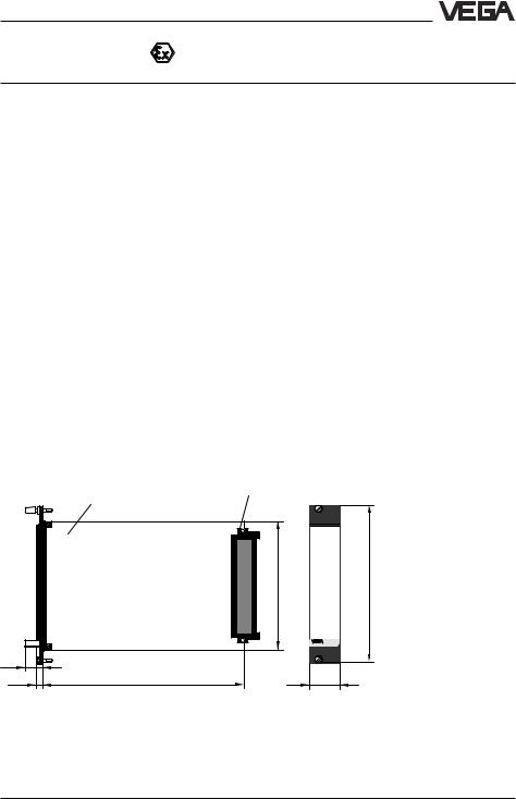
B = 25.4 mm (5 TE), H = 128.4 mm, T = 162 mm |
|
CE conformity
VEGAMET 514 and VEGAMET 514 Ex signal conditioning instruments meet the protective regulations of EMC (89/336/EWG) and NSR (73/23/EWG). Conformity has been judged acc. to the following standards:
EMC Susceptibility Immission
NSR
8 |
VEGAMET 514 |
Product description
Ex technical data
Power supply
Operating voltage |
Unom corresponds to non-Ex version |
|
|||||||
|
Reference voltage |
Um = 250 V AC or 125 V DC |
|
||||||
Meas. data input (intrinsically safe circuit) on VEGAMET 513 Ex 2-times available |
|
||||||||
|
Flame proofing |
[EEx ia] IIC, [EEx ia] IIB, [EEx ib] IIC or |
|||||||
|
|
|
[EEx ib] IIB |
|
|
|
|||
|
Max. values |
|
|
|
|
|
|
|
|
- |
voltage |
UO = 20 V |
|
|
|
||||
- |
current |
IO = 128 mA |
|
|
|
||||
- |
power |
PO = 640 mW |
|
|
|
||||
|
Characteristics |
linear |
|
|
|
|
|||
|
Effective inner inductance LI |
negligible |
|
|
|
||||
|
Effective inner capacitance CI |
negligible |
|
|
|
||||
|
|
|
|
|
|
|
|
|
|
|
|
|
EEx ia IIC |
|
EEx ia IIB |
EEx ib IIC |
EEx ib IIB |
||
|
|
|
|
|
|
|
|
|
|
|
Max. permissible outer inductance LO (mH) |
0.5 |
1 |
|
1.5 |
2 |
2 |
9 |
|
|
|
|
|
|
|
|
|
|
|
|
Max. permissible outer capacitance CO (nF) |
97 |
78 |
|
68 |
486 |
200 |
1000 |
|
|
|
|
|
|
|
|
|
|
|
The intrinsically safe circuits are reliably separated from the non-intrinsically safe circuits up to a peak value of the nominal voltage of 375 V. The max. voltage on the non-intrinsically safe circuits should not exceed 250 Veff in case of failure.
1.5 Dimensions
Circuit board 100 x 160 x 1.5 |
Multipoint |
5 TE |
European size |
connector |
100 |
128,4 |
15 |
|
|
5,5 |
162 |
25,4 |
VEGAMET 514 |
9 |

Mounting
2 Mounting
VEGAMET 514 signal conditioning instruments can be either mounted with a module in a carrier BGT 596 or BGT
596 Ex.M or in a single housing type 505.
Mounting in carrier
Mount the respective module (standard or Ex version) in your carrier. Wire the terminals of the multipoint connector according to the wiring plan.
Module
Multipoint connector DIN 41 612, series F, 33pole (d, b, z) with coded pins and mounting material for mounting in carrier BGT 596 or BGT 596 Ex.M.
Module Ex
Multipoint connector DIN 41 612, series F, 33pole (d, b, z) with coded pins, Ex separating chamber and mounting material for mounting in carrier BGT 596 Ex.M.
The multipoint connector is available in the following versions:
-Wire-Wrap standard connection
1.0x 1.0 mm
-Plug connection 2.8 x 0.8 mm
-Termi-Point standard connection
1.6x 0.8 mm
-Soldering connection
-Screw terminals 2 x 0.5 mm2
For further mounting information, see the operating instructions of the carrier.
Mounting in single housing
Either screw the housing socket directly to the mounting plate or plug it onto a carrier rail (35 x 15 acc. to EN 50 022 or 32 acc. to
EN 50 035). Connect the terminals according to the wiring plans on the following pages. For further mounting information see the operating instructions of the housing.
Transparent cover
To protect the instrument against unauthorised adjustment, the front plate of VEGAMET can be provided with a lockable transparent cover (supplied with the instrment).
Coding
To prevent an interchanging of the different signal conditioning instruments, the multipoint connector of carrier or the housing can be provided with coded pins.
Note:
The coding is absolutely necessary for Ex instruments!
The multiple plug of the signal conditioning instrument is equipped with respective holes (mechanical coding). Instrument coding ensures that the different signal conditioning instruments cannot be interchanged. The appropriate coded pins are supplied with each module or housing. Equip the multipoint connector with these coded pins acc. to the following table.
|
|
|
|
|
|
|
|||||
|
|
|
|
|
|
|
|
|
|||
VEGAMET 514 |
|
a3 / c5 |
|
|
–– |
||||||
VEGAMET 514 Ex |
|
a3 / c5 |
|
|
c23 |
||||||
|
|
|
|
|
|
|
|
|
|
|
|
|
|
|
|
z |
b |
d |
|
|
|
|
|
|
|
|
|
|
|
|
|
|
|
|
|
|
|
|
|
|
a |
c |
|
|
|
|
|
|
|
|
|
|
o 1 o |
|
|
|
|
||
a3 |
|
|
|
|
o 3 o |
|
c5 |
|
|||
|
|
|
|
|
|
||||||
|
|
|
|
|
o 5 o |
|
|
||||
|
|
|
|
|
o 7 o |
|
|
|
|
||
|
|
|
|
|
o 9 o |
|
|
|
|
||
|
|
|
|
|
o11o |
|
|
|
|
||
|
|
|
|
|
o13o |
|
|
|
|
||
|
|
|
|
|
o15o |
|
|
|
|
||
|
|
|
|
|
o17o |
|
|
|
|
||
|
|
|
|
|
o19o |
|
|
|
|
||
|
|
|
|
|
o21o |
|
|
|
|
||
|
|
|
|
|
o23o |
|
c23 |
|
|||
|
|
|
|
|
o25o |
|
|
|
|
||
|
|
|
|
|
o27o |
|
|
|
|
||
|
|
|
|
|
o29o |
|
|
|
|
||
|
|
|
|
|
o31o |
|
|
|
|
||
|
|
|
|
|
|
|
|
|
|
|
|
|
|
|
|
|
|
|
|
|
|
|
|
|
|
|
|
|
|
|
|
|
|
|
|
10 |
VEGAMET 514 |
Electrical connection
3 Electrical connection
3.1 Connection instructions
Note the following instructions for electrical connection:
-The connection must be made acc. to the local installation standards (e.g. in Germany acc. to the VDE-regulations).
-The wiring between VEGAMET and sensor can be done with standard two-wire cable.
-If strong electromagnetic interferences are expected, screened cable is recommended. The screening must be earthed on both ends.
-The line resistances stated in the technical data must not be exceeded.
-If overvoltages are expected, we recommend a sensor electronics with integrated overvoltage protection or the installation of VEGA overvoltage arresters.
-The voltage supply of VEGAMET must provide with extra-low voltage to ensure protection class II. When using VEGASTAB 593 a reliable separation from the mains circuits acc. to DIN VDE 0106, part 101 is ensured.
3.2Connection instructions for Ex approved applications
The signal conditioning instruments must be generally mounted outside the hazardous areas, or special Ex protective measures must be taken.
Ex separating chamber
To ensure sufficient "air and creep distance", an Ex separating chamber must be mounted to the connections of VEGAMET. Lead the cables through the Ex separating chamber and connect them. Fasten the Ex separating chamber with the lower screw. Note the operating instructions of the carrier BGT 596 Ex.M.
Protection in Ex applications
In Ex applications a protection class of IP 20 must be maintained. To accomplish this, cover the gaps or free modules from the front with suitable blind covers.
Mounting in carriers
If you mount your VEGAMET with Ex approval in a carrier, you have to use a VEGAEx module. Keep a distance of at least 10 mm (2 TE) to module cards of other manufacturers. If you want to mount VEGAMET at the utmost left position in the carrier, you have to mount a blind cover with at least 20 mm
(4 TE) in front of the module of the instrument.
%
100
- 

 +
+
ESC 

 OK
OK
 CONNECT 1 2
 on
on
Blind cover (4 TE)
VEGAMET 514 |
11 |
Electrical connection
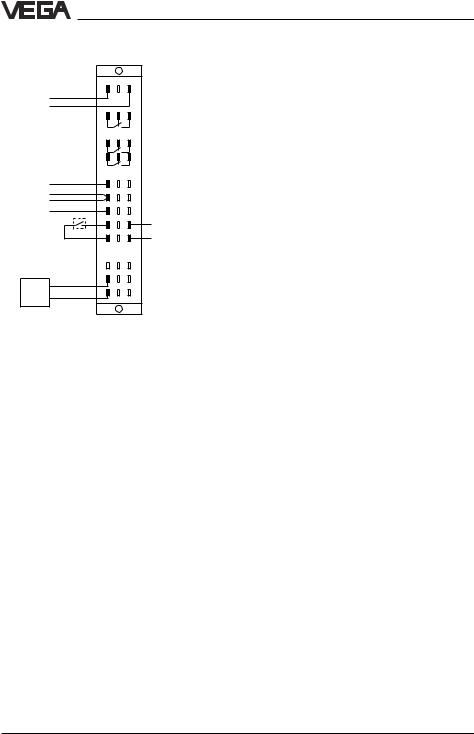
3.3 Wiring plan
|
|
d |
b |
z |
Supply |
L (+) |
2 |
+ |
- |
|
|
|
||
voltage |
N (-) |
|
|
|
|
|
6 |
|
|
|
|
10 |
|
|
|
|
12 |
|
|
|
|
16 + |
|
+ |
Current output |
18 - |
|
|
|
Voltage output |
20+ |
|
|
|
|
|
22 + |
|
+ |
Correction signal |
24 - |
|
- |
|
(input 4) |
|
|
|
|
|
|
28 |
|
|
|
|
+ |
|
|
|
+ |
30 |
- |
|
|
|
32 |
|
|
|
- |
|
|
|
Sensor |
|
|
|
|
(input 1) |
|
|
|
|
Fail safe relay
Level relay 1 Level relay 2
DISBUS output
Ex version
For connection of Ex certified instruments, please note the instructions in the attached official documents as well as the valid mounting regulations. Make sure that the Ex separating chamber is mounted to the multipoint connector. Always lead the cables through the Ex separating chamber. Also note the operating instructions of the carrier
BGT 596 Ex.M and the Ex instructions.
12 |
VEGAMET 514 |

Adjustment
4 Adjustment
4.1Indicating and adjustment elements
Circuit board
A rotary switch is located on the circuit board. It is used for adjustment of the instrument address on DISBUS. This setting is necessary if several VEGAMET signal conditioning instruments are linked via the DISBUS or if you control a VEGADIS 174 indicating instrument via the DISBUS.
The adjustment range 1 … F corresponds to the DISBUS addresses 1 … 15.
Factory setting: 1
Note:
With address 0 the VEGAMET does not participate in the DISBUS communication.
Rotary switch
7 |
8 |
9 |
|
|
10 |
6 |
|
A |
|
|
|
5 |
|
B |
11 |
||
|
|
|
|||
4 |
|
|
|
C |
12 |
3 |
|
|
|
D |
13 |
|
|
|
|
|
|
2 |
|
E |
|
14 |
|
1 |
0 |
F |
|
||
|
15 |
||||
|
|
||||
|
|
|
|
||
|
|
|
|
|
|
The set instrument address on the DISBUS can be indicated via the LC display.
Note
If several VEGAMET are linked via the DISBUS, each address must only be assigned once!
Position of the rotary switch
Rotary switch
Front plate VEGAMET 514
without adjustment |
with adjustment |
module |
module |
1
2
|
|
|
|
% |
|
|
|
|
100 |
|
|
|
- |
+ |
|
|
3 |
|
3 |
|
|
4 |
ESC |
OK |
|
|
|
|
|
|
CONNECT |
5 |
|
CONNECT |
1 |
2 |
1 |
2 |
|
|
on |
6 |
|
on |
|
|
|
||
|
514 |
7 |
|
514 |
1 LCD (4 lines with 6 figures each, illuminated) for clear text indication
2 LED chain (yellow) for quasi-analogue indication of the measured value
3 Keys for menu adjustment
4 Connection socket for VEGACONNECT
5 LED (yellow) lights if the relay is energised (standard setting)
6 LED (red), lights if fail safe relay is deenergised 7 LED (green), lights if operating voltage is on
VEGAMET 514 |
13 |
Adjustment
4.2 Adjustment system
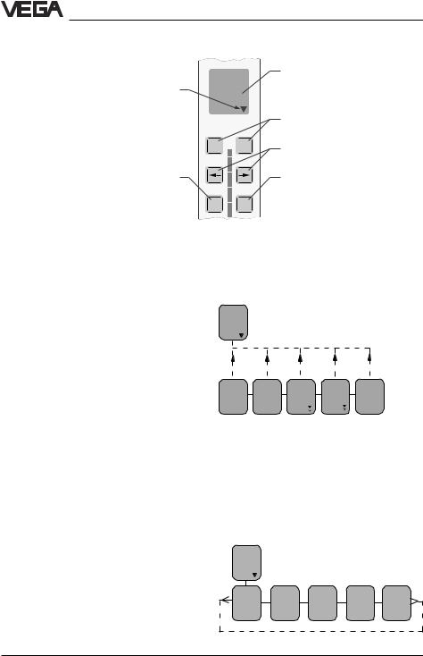
Indicating and adjustment module
Branching point, i.e. jump to the next lower menu with [OK]
%
100
- 

 +
+
Depending on the menu item, interrupt adjustment or change to the next higher menu
ESC OK
Indication of
-measured value
-menu item
-parameter
Depending on the menu item, change value or choose out of a list
Choose menu item
Depending on the menu item, save the set value or change to the underlying menu
Reduced menu - extended menu
Two menu modes are available: the mode "reduced menu" and the mode "extended menu".
Note:
VEGAMET 514 is preset to automatically place in the menu mode "reduced menu"!
In the majority of all applications, you can carry out the necessary settings in this menu mode (see also chapter 4.5 Comparison of the menu modes).
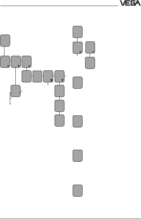
Adjustment structure
The adjustment is made via 6 keys in conjunction with the text display. The jump from the measured value display to the underlying menu is made with [OK]. Use [–>] or [<–] to change within this menu level from one menu item to the other. A branching point is indicated by the symbol ▼ and enables with [OK] a jump to the underlying menu item. Parameters can be recognised by the absence of the symbol ▼ . The value of the parameters can be modified with [+] or [–] or chosen out of a list. The modified value can be saved with [OK]. To interrupt a setting (without saving the modification), you have to push [ESC]. A jump back to the next higher menu item is made with [ESC]. 15 minutes
after pushing a key for the last time, an automatic reset to the measured value display is triggered. A jump back to the next higher menu level with [ESC] is possible from each menu item , even if no connecting line is shown in the menu schematics.
Add'l functions
ESC |
ESC |
ESC |
ESC |
ESC |
Pass- |
Lang- |
TAG 1 |
Reset |
Menu |
word |
uage |
to de |
TAG 1 |
mode |
|
Eng- |
fault |
|
Redu- |
off |
lish |
|
|
ced |
If you are in the utmost right menu item of a menu row and push the [–>] key, you will immediately reach the utmost left menu item of this row. You also reach immediately the right menu item from the left one, if you push the [<–] key.
These shortcuts (shown with a broken line) are not shown in the menu schematics in order to give a better overview.
Volt output 1
prop. |
Unit |
Volt |
Fail- |
Volt |
to |
|
out- |
ure |
limita- |
Per- |
|
put |
mode |
tion |
cent |
0,0% |
0/10V |
0V |
on |
14 |
VEGAMET 514 |
Adjustment
Format examples of the menu schematic
In white letters you see the param-  eters which can be modified with the [+] or [–] key and saved with the
[OK] key. Examples:
-In the menu item "Language" you can change from German to English.
Bold print/italic entries, e.g. the
 measurement loop name "TAG-No. 1" can differ if you have made a corresponding parameter adjustment or
configuration of the measurement loop. In the menu schematics you will see the factory settings.
Volt Light grey menu items are only dis-
at played if necessary (depending on
0%
0,000 the adjustments made in the other menu items).
4.3 Adjustment via PC
Signal conditioning instrument with adjustment module
Setup
-directly via the keys of the adjustment module
-or with a PC, equipped with VVO software (VEGA Visual Operating) and an interface adapter VEGACONNECT.
Signal conditioning instrument without adjustment module
Setup
-with a PC, equipped with VVO software (VEGA Visual Operating) and an interface adapter VEGACONNECT.
Change of the menu mode:
Move from the display of measured value (TAG-No.1) to the menu item "Menu mode reduced". Now push [+] twice until "Menu mode Extended" appears, then push [OK].
TAG-
No. 1
% |
|
|
|
|
|
|
xx,x |
|
|
|
|
|
|
Param. |
Confi- |
Add'l |
|
|
|
|
TAG- |
gura- |
func- |
|
|
|
|
No. 1 |
tion |
tions |
|
|
|
|
|
|
Pass- |
Lang- |
TAG 1 |
Reset |
Menu |
|
|
word |
uage |
to de- |
TAG 1 |
mode |
|
|
|
Eng- |
fault |
|
Redu- |
|
|
off |
lish |
|
|
ced |
|
|
|
|
|
|
Ex- |
|
|
|
|
|
|
tended |
%
100
- 

 +
+
ESC 

 OK
OK
CONNECT
 1
1 2
2 
VEGACONNECT
 on
on
515
PC with VVO software
VEGAMET 514 |
15 |

Adjustment
4.4Configuration and parameter adjustment
Independent of whether you set up your VEGAMET via the keys of the adjustment module or via a PC with the software VVO, the procedure is always the same.
Proceed in the following sequence:
-configuration (if not already configured as factory setting)
-parameter adjustment.
In this operating instruction manual, the adjustment steps are described which are directly carried out on the keys of VEGAMET. The adjustment via the software VVO is described in a separate manual.
Configuration
Configuring means assigning or setting (once) function. VEGAMET requires a (mostly once) basic co-ordination, determining the applications and the assignments of the inputs and outputs. Choices can be made from existing functions and options. This procedure is called configuration. The signal conditioning instruments are delivered with a configuration which only needs to be changed in special cases.
The basic configuration includes the following steps:
1 Configuration measurement loop
•Choose the kind of application (level, gauge…)
•Choose sensor type (capacitive, hydrostatic…)
•Specify application (standard, level difference…)
•Determine options (no option, corrections…)
Note:
The measurement loop configuration can only be modified if a "Reset to single measurement" has been carried out previosly (under "Additional functions" in the extended menu). If you only want to modify the sensor type, you first have to carry out "Reset TAG 1" (under "Additional functions" in the reduced menu).
2 Configuration, inputs
•Determine from where your VEGAMET receives the input data (sensor, other VEGAMET)
•Enter sensor characteristics values (meas. range, current range)
3 Configuration, outputs
•All outputs (except fail-safe relay) can be assigned to a sensor or can be switched off.
After basic configuration, VEGAMET starts operating and indicates the actual measured value. The other configurations should be carried out after the parameter adjustment.
Parameter adjustment
Parameter adjustment means changing the values. Signal conditioning instruments have many parameters, the values of which can be modified, such as for example the integration time of 0 … 600 s. The modification of these values is called parameter adjustment. The parameter adjustment does not influence the configuration. Take notice that parameter adjustment is only possible after a configuration has been done (e.g. set values of the current input when the current output has been assigned).
16 |
VEGAMET 514 |

Adjustment
4.5 Comparison: reduced menu – extended menu
In the table the most important functions of VEGAMET 514 are listed – each with a mark indicating in which menu mode the functions are available.
Function |
Reduc. |
Ext. |
|
menu |
menu |
|
|
|
Adjustment with medium |
x |
x |
|
|
|
Adjustment without medium |
x |
x |
|
|
|
Set integration time |
x |
x |
|
|
|
Simulation |
x |
x |
|
|
|
Switch over current output (4/20 mA, 0/20 mA, 20/4 mA, 20/0 mA) |
x |
x |
|
|
|
Switch over voltage output (2/10 V, 0/10 V, 10/2 V, 10/0 V) |
x |
x |
|
|
|
Changeover relay mode (overfill protection – dry run protection) |
x |
x |
|
|
|
Scaling (display) |
x |
x |
|
|
|
Change menu mode (reduced – extended) |
x |
x |
|
|
|
Change menu language |
x |
x |
|
|
|
Activate/deactivate password |
x |
x |
|
|
|
Change sensor type |
x |
x |
|
|
|
Change measurement loop name |
x |
x |
|
|
|
Reset measurement loop (Reset TAG) |
x |
x |
|
|
|
Reset measurement loop to default (TAG to default) |
x |
x |
|
|
|
Use correction input |
– |
x |
Edit linearisation curves |
– |
x |
|
|
|
Change mode (e.g. level – gauge) |
– |
x |
|
|
|
Select different reference values for outputs |
– |
x |
|
|
|
Define output behaviour (current/voltage output) in case of failure |
– |
x |
|
|
|
Adapt VEGAMET to sensor characteristics values |
– |
x |
|
|
|
Offset correction during adjustment |
– |
x |
|
|
|
Adjust relay switching delay |
– |
x |
|
|
|
Reset level |
– |
x |
|
|
|
Assign inputs (from another VEGAMET) |
– |
x |
|
|
|
Switch on/off current/voltage limitation |
– |
x |
|
|
|
Individual setting of current/voltage output values between 0 … 20 mA/0 … 10 V |
– |
x |
|
|
|
Manual offset correction |
– |
x |
|
|
|
Manual real value correction |
– |
x |
|
|
|
Info indication |
– |
x |
|
|
|
|
|
|
VEGAMET 514 |
|
17 |

Setup
5 Setup
•Adjust the VEGAMET instrument address on the circuit board by means of the rotary switch (only necessary, if several VEGAMET are connected by means of DISBUS).
•Install VEGAMET.
•Connect sensor and power supply.
•After switching on, the display indicates for approx. 10 secs the instrument type and the software version, e.g. "MET 514 V1.12".
•If a measurement loop has not yet been configured, the display shows "Configuration", the red failure LED also lights. In this case, proceed as described under "6.1 Configuration of measurement loop".
•If a measurement loop is already configured, the display shows a value, e.g. "TAG-No. 1 21.8 %".You can now carry out the settings, as described in the chapter "6 Settings in the reduced menu".
18 |
VEGAMET 514 |
Settings in the "reduced menu"
6 Settings in the "reduced menu"
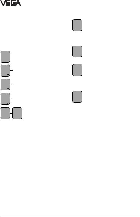
6.1 Configuration of measurement loop
Choose sensor type
TAG- Meas. No. 1 value
% indication xx,x
Param. |
Confi- |
Add'l |
|
|
|
TAG- |
gura- |
func- |
|
|
|
No. 1 |
tion |
tions |
|
|
|
|
|
Pass- |
Lang- |
TAG 1 |
Reset |
|
|
word |
uage |
to de- |
TAG 1 |
|
|
|
Eng- |
fault |
|
|
|
off |
lish |
|
|
|
Sensor |
|
|
|
Delete |
|
type |
It is only possible to |
|
TAG |
|
|
Hydro- |
|
1? |
||
|
modify the sensor type, |
||||
|
static |
|
|||
|
when a "Reset TAG 1" was |
|
|||
|
capa- |
|
|||
|
carried out before. |
|
|
||
|
citive |
|
|
|
Reset |
|
VEGADIF |
|
|
|
OK ? |
|
|
|
|
|
Reset |
|
|
|
|
|
Now! |
|
|
|
|
|
OK ? |
By default, VEGAMET 514 is configured for connection to a hydrostatic sensor. If, for example, you use a capacitive electrode, you have to proceed as follows:
Move to the menu item "Sensor type Hydrostatic".
Push [+] or [–] once. The word "Hydrostatic" flashes. You are now in the editing mode. Continue pushing [+] or [–] until the display shows "Sensor type capacitive". You are still in the editing mode.
Now push the [OK] key. By doing this, you save the settings and quit the editing mode.
Name measurement loop
TAG- |
|
You can modify the meas- |
|
No. 1 |
|
urement loop name "TAG- |
|
% |
|
|
|
xx,x |
|
No. 1", if you want a more |
|
|
|
|
useful designation. |
Param. |
Confi- |
Two lines with six figures |
|
TAG- |
|
gura- |
each are available. To do |
No. 1 |
tion |
||
|
|
|
this, move to the menu item |
|
|
TAG |
"TAG name …". |
|
|
|
|
|
|
name |
|
|
|
TAG - |
|
|
|
No. 1 |
|
Push [+] or [–] once. The first character of the measurement loop name, in this example the letter T, flashes (editing mode). Continue pushing the
[+] or [–] key, by doing this you scroll through the alphabet, through the row of numbers and through a list of characters.
When you have reached the requested character, push [–>]. The next character is activated and begins flashing. Scroll again with [+]
and [–] to the requested character. With [–>] you again move to the next character.
When you have finished the last position of the name and you have "written" the name of the measurement loop in this way, you have to
push [OK] to save the setting. If you quit the menu item without saving, the name of the measurement loop is again "TAG-No. 1".
Ves.4 |
In the display of measured value and |
|
all other menu items in which the |
||
Hall 3 |
||
% |
measurement loop name is shown, |
|
27,8 |
you will now see the new designation. |
|
|
VEGAMET 514 |
19 |
Settings in the "reduced menu"
6.2 Adjustment with medium
You can either carry out the adjustment with medium or without medium. Adjustment with medium means that you carry out the adjustment taking the actual level into account. To carry out an adjustment with medium, it is necessary to know the percentage value of the actual vessel filling.
TAG- |
|
No. 1 |
|
% |
|
xx,x |
|
Param. |
|
TAG- |
|
No. 1 |
|
Ad- |
|
just- |
|
ment |
|
with |
|
medium |
|
Min- |
Max- |
adjust |
adjust |
at % |
at % |
0,0 |
100,0 |
In this procedure, the percentage values which correspond to the actual min. and max fillings are entered. The adjustment sequence of the min. and max. value is unimportant. When you know, for example, that your filling is actually 80 %, you can enter in the menu max. adjustment the value "80". Later when your filling is, for example, 10 %, you enter in the menu min. adjustment the value "10".
The bigger the difference between the two adjustment points, the more precise the measurement over the whole measuring curve. An adjustment at 0 % and 100 % would be ideal. For practical reasons, it is not always possible to completely empty or fill a vessel. The distance between the two adjustment points, however, should be at least
10 % of the sensor range.
Adjustment example
You know that your vessel is actually filled up to 80%. Move to the menu
100,0 item "Max. adjust at % 100.0". Push the [–] key briefly, so that the figure
100.0 flashes (editing mode).
Max- |
Continue pushing [–] until the figure |
adjust |
80.0 appears on the display. Now |
at % |
push [OK] to save the adjustment. |
80,0 |
|
Min- |
Later, when your filling is, for exam- |
adjust |
ple, 10 %, go to the menu item |
at % |
"Min. adjust at % 0.0". Briefly push |
0,0 |
|
|
[+], until the figure 0.0 flashes |
|
(editing mode). |
Min- |
Continue pushing [+] until "10" ap- |
adjust |
pears on the display. Now push [OK] |
at % |
|
10,0 to save the adjustment.
You can of course carry out the adjustment with medium at 0 % and 100 % filling. Note: The figures 0 % and 100 % must flash (editing mode), before they can be saved with the [OK] key.
20 |
VEGAMET 514 |
Loading...