


PULS63
Table of contents
 Loading...
Operating Instruction
s
VEGAPULS 63
4 … 20 mA/HART - two-wire
Document ID:
28436
R
adar

Contents
1 About this
document
1.1 Function. . . . . . . . . . . . . . . . . . . . . . . . . . . . . . . . . .
4
1.2 Target group . . . . . . . . . . . . . . . . . . . . . . . . . . . . . .
4
1.3 Symbolism used. . . . . . . . . . . . . . . . . . . . . . . . . . . .
4
2 For your safety
2.1 Authorised personnel . . . . . . . . . . . . . . . . . . . . . . . .
5
2.2 Appropriate use . . . . . . . . . . . . . . . . . . . . . . . . . . . .
5
2.3 Warning about misuse . . . . . . . . . . . . . . . . . . . . . . .
5
2.4 General safety instructions . . . . . . . . . . . . . . . . . . . .
5
2.5 Safety label on the instrument . . . . . . . . . . . . . . . . . .
6
2.6 CE conformity . . . . . . . . . . . . . . . . . . . . . . . . . . . . .
6
2.7 Fulfillment of NAMUR recommendations . . . . . . . . . .
6
2.8 FCC/IC conformity (only for USA/Canada) . . . . . . . . .
6
2.9 Safety instructions for Ex areas . . . . . . . . . . . . . . . . .
6
2.10 Environmental instructions. . . . . . . . . . . . . . . . . . . . .
7
3 Product description
3.1 Structure . . . . . . . . . . . . . . . . . . . . . . . . . . . . . . . . .
8
3.2 Principle of operation . . . . . . . . . . . . . . . . . . . . . . . .
9
3.3 Operation. . . . . . . . . . . . . . . . . . . . . . . . . . . . . . . . .
10
3.4 Packaging, transport and storage . . . . . . . . . . . . . . .
10
4 Mounting
4.1 General instructions . . . . . . . . . . . . . . . . . . . . . . . . .
12
4.2 Instructions for installation . . . . . . . . . . . . . . . . . . . . .
14
5 Connecting to power supply
5.1 Preparing the connection . . . . . . . . . . . . . . . . . . . . .
20
5.2 Connection procedure. . . . . . . . . . . . . . . . . . . . . . . .
21
5.3 Wiring plan, single chamber housing . . . . . . . . . . . . .
22
5.4 Wiring plan, double chamber housing . . . . . . . . . . . .
24
5.5 Wiring plan, double chamber housing Ex d . . . . . . . .
26
5.6 Wiring plan - version IP 66/IP 68, 1 bar . . . . . . . . . . .
28
5.7 Switch on phase. . . . . . . . . . . . . . . . . . . . . . . . . . . .
28
6 Set up with the indicating and adjustment module PLICSCOM
6.1 Short description . . . . . . . . . . . . . . . . . . . . . . . . . . .
29
6.2 Insert indicating and adjustment module. . . . . . . . . . .
29
6.3 Adjustment system . . . . . . . . . . . . . . . . . . . . . . . . . .
31
6.4 Setup steps . . . . . . . . . . . . . . . . . . . . . . . . . . . . . . .
32
6.5 Menu schematic. . . . . . . . . . . . . . . . . . . . . . . . . . . .
39
6.6 Saving the parameter adjustment data . . . . . . . . . . . .
41
7 Set up with PACTware and other adjustment programs
7.1 Connect the PC . . . . . . . . . . . . . . . . . . . . . . . . . . . .
42
7.2 Parameter adjustment with PACTware . . . . . . . . . . . .
43
2 VEGAPULS 63 • 4 … 20 mA/HART - two-wire
Contents
28436-EN-120530

7.3 Parameter adjustment with AMS™ and PDM .
. . . . . .
44
7.4 Saving the parameter adjustment data . . . . . . . . . . . .
44
8 Maintenance and fault rectification
8.1 Maintenance . . . . . . . . . . . . . . . . . . . . . . . . . . . . . .
45
8.2 Remove interferences. . . . . . . . . . . . . . . . . . . . . . . .
45
8.3 Exchanging the electronics module . . . . . . . . . . . . . .
46
8.4 Software update . . . . . . . . . . . . . . . . . . . . . . . . . . . .
47
8.5 Instrument repair . . . . . . . . . . . . . . . . . . . . . . . . . . .
48
9 Dismounting
9.1 Dismounting steps . . . . . . . . . . . . . . . . . . . . . . . . . .
49
9.2 Disposal . . . . . . . . . . . . . . . . . . . . . . . . . . . . . . . . .
49
10 Annex
10.1 Technical data . . . . . . . . . . . . . . . . . . . . . . . . . . . . .
50
10.2 Dimensions . . . . . . . . . . . . . . . . . . . . . . . . . . . . . . .
59
Supplementary documentation
Information:
Suppleme
ntary documents appropriate to the ordered version come
with the delivery. You can find them listed in chapter "Product
description".
Instructions manuals for accessories and replacement parts
Tip:
To ensu
re reliable setup and operation of your VEGAPULS 63, we
offer accessories and replacement parts. The corresponding doc-
umentations are:
l 27835 - Indicating and adjustment module PLICSCOM
l 32628 - Interface adapter VEGACONNECT
l 27720 - External indication VEGADIS 61
l 34296 - Protective cover
l 30176 - Electronics module VEGAPULS series 60
l 31088 - Flanges according to DIN-EN-ASME-JIS
Editing status: 2012-05-25
VEGAPULS 63 • 4 … 20 mA/HART - two-wire 3
Contents
28436-EN-120530
1 About this document
1.1 Function
Th
is operating instructions manual provides all the information you
need for mounting, connection and setup as well as important
instructions for maintenance and fault rectification. Please read this
information before putting the instrument into operation and keep this
manual accessible in the immediate vicinity of the device.
1.2 Target group
This operating instructions manual is directed to trained qualified
personnel. The contents of this manual should be made available to
these personnel and put into practice by them.
1.3 Symbolism used
Information, tip, note
This
symbol indicates helpful additional information.
Caution: If this
warning is ignored, faults or malfunctions can
result.
Warning: If this warning is ignored, injury to persons and/or serious
damage to the instrument can result.
Danger: If this warning is ignored, serious injury to persons and/or
destruction of the instrument can result.
Ex
applications
Th
is
symbol indicates special instructions for Ex applications.
l List
The dot set in front indicates a list with no implied sequence.
à Action
This a
rrow indicates a single action.
1 Sequence
Numbers set in front indicate successive steps in a procedure.
Battery disposal
This
symbol characterizes the special information for disposal of
batteries and accumulators.
4 VEGAPULS 63 • 4 … 20 mA/HART - two-wire
1 About this document
28436-EN-120530

2 For your safety
2.1 Auth
orised personnel
All operations described in this operating instructions manual must be
carried out only by trained specialist personnel authorised by the plant
operator.
During work on and with the device the required personal protective
equipment must always be worn.
2.2 Appropriate use
VEGAPULS 63 is a sensor for continuous level measurement.
You can find detailed information on the application range in chapter
"Product description".
Operational reliability is ensured only if the instrument is properly used
according to the specifications in the operating instructions manual as
well as possible supplementary instructions.
For safety and warranty reasons, any invasive work on the device
beyond that described in the operating instructions manual may be
carried out only by personnel authorised by the manufacturer. Arbitrary
conversions or modifications are explicitly forbidden.
2.3 Warning about misuse
Inappropriate or incorrect use of the instrument can give rise to
application-specific hazards, e.g. vessel overfill or damage to system
components through incorrect mounting or adjustment.
2.4 General safety instructions
This is a high-tech instrument requiring the strict observance of
standard regulations and guidelines. The user must take note of the
safety instructions in this operating instructions manual, the country-
specific installation standards as well as all prevailing safety
regulations and accident prevention rules.
Depending on the model, the emitting frequencies of all radar sensors
are either in the C or K band range. The low transmitting power lies far
below the internationally permitted limit values. When the instrument is
used correctly, it presents no danger to human health. It may be
operated without restriction outside of closed metallic vessels.
The instrument must only be operated in a technically flawless and
reliable condition. The operator is responsible for trouble-free
operation of the instrument.
VEGAPULS 63 • 4 … 20 mA/HART - two-wire 5
2 For your safety
28436-EN-120530

During the entire duration of use, the user
is obliged to determine the
compliance of the necessary occupational safety measures with the
current valid rules and regulations and also take note of new
regulations.
2.5 Safety label on the instrument
The safety approval markings and safety tips on the device must be
observed.
2.6 CE conformity
This device fulfills the legal requirements of the applicable EC
guidelines. By attaching the CE mark, VEGA provides a confirmation
of successful testing. You can find the CE conformity declaration in the
download area of "
www.vega.com".
2.7 Fulfillment o
f NAMUR recommendations
The device fulfills the requirements of the applicable NAMUR
recommendations.
2.8 FCC/IC conformity (only for USA/Canada)
VEGAPULS sensors with all antenna versions are FCC/IC approved.
Modifications not expressly approved by VEGA will lead to expiry of
the operating licence according to FCC/IC.
VEGAPULS 63 is in conformity with part 15 of the FCC directives and
fulfills the RSS-210 regulations. Note the corresponding regulations for
operation:
l The instrument must not cause any interfering emissions
l The device must be insensitive to interfering immissions, including
those that may cause undesirable operating conditions
According to chapter "Dimensions" of this operating instructions
manual, the instrument is designed for operation with an antenna with
a max. amplification of 33 dB. The instrument must not be operated
with antennas not listed therein or those having an amplification of
more than 33 dB. The required antenna impedance is 50 Ω.
2.9 Safety instructions for Ex areas
Please note the Ex-specific safety information for installation and
operation in Ex areas. These safety instructions are part of the
operating instructions manual and come with the Ex-approved
instruments.
6 VEGAPULS 63 • 4 … 20 mA/HART - two-wire
2 For your safety
28436-EN-120530

2.10 Environmental instructions
Protection
of the environment is one of our most important duties. That
is why we have introduced an environment management system with
the goal of continuously improving company environmental protection.
The environment management system is certified according to DIN
EN ISO 14001.
Please help us fulfil this obligation by observing the environmental
instructions in this manual:
l Chapter "Packaging, transport and storage"
l Chapter "Disposal"
VEGAPULS 63 • 4 … 20 mA/HART - two-wire 7
2 For your safety
28436-EN-120530

3 Product description
3.1 Structure
Th
e VEGAPULS 63 radar sensor is available in two electronics
versions:
l Standard electronics type PS60KKH
l Electronics with increased sensitivity type PS60KKD
The respective version can be determined by means of the type label
on the electronics.
The electronics version influences the CE conformity, the functional
safety (SIL), the factory setting for product selection and vessel form,
the accuracy, the voltage supply as well as the approvals of
VEGAPULS 63. The differences are specified in this operating
instructions manual in the respective paragraphs.
The scope of delivery encompasses:
l VEGAPULS 63 radar sensor
l Documentation
- this operating instructions manual
- Safety Manual 31338 "VEGAPULS series 60 - 4 … 20 mA/
HART"
1)
- Operating instructions manual 27835 "Indicating and adjust-
ment module PLICSCOM" (optional)
- Supplementary instructions manual 31708 "Heating for in-
dicating and adjustment module" (optional)
- Supplementary instructions manual "Plug connector for con-
tinuously measuring sensors" (optional)
- Ex-specific "Safety instructions" (with Ex versions)
- if necessary, further certificates
The VEGAPULS 63 consists of the components:
l Process fitting with flange
l Housing with electronics, optionally available with plug connector,
optionally available with connection cable
l Housing cover, optionally available with indicating and adjustment
module PLICSCOM
The components are available in different versions.
1)
Not with version for
temperatures < -40 °C (-40 °F) (optional)
Vers
ions
Scope of delivery
Constituent parts
8 VEGAPULS 63 • 4 … 20 mA/HART - two-wire
3 Product description
28436-EN-120530
3
2
1
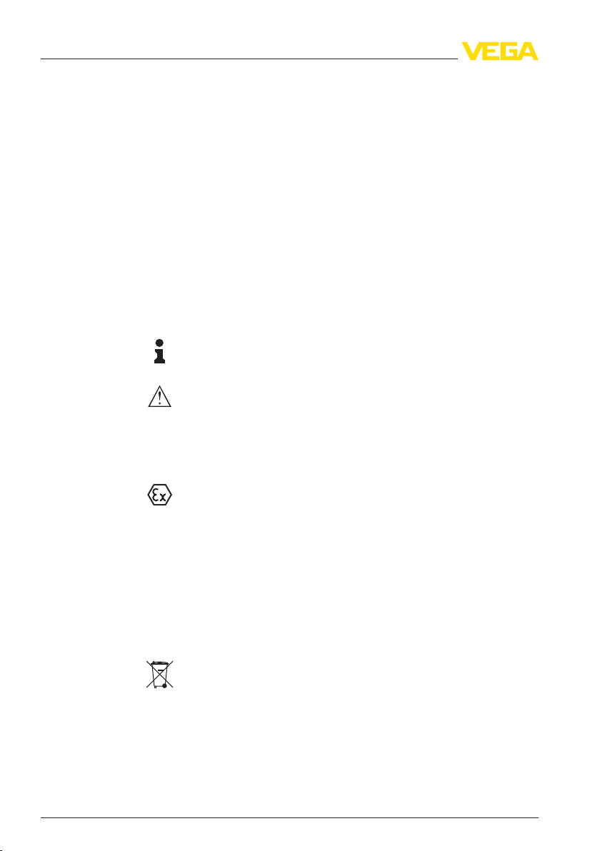
Fig. 1: VEGAPULS 63 - flange version with
plastic housing
1 Housing cover with integrated PLICSCOM (optional)
2 Housing with electronics
3 Process fitting with encapsulated antenna system
The type label contains the most important data for identification and
use of the instrument:
l Instrument type
l Article and serial number device
l Article numbers, documentation
l Technical data: Approvals, antenna type, process fitting, process
seal/temperature, signal output, voltage supply, protection, pro-
tection class
l SIL identification (with SIL rating ex works)
With the serial number, you can access the delivery data of the
instrument via
www.vega.com, "VEG
A
T
ools" and "serial number
search". In addition to the type label outside, you can also find the
serial number on the inside of the instrument.
3.2 Principle of operation
VEGAPULS 63 is a radar sensor in K-band technology (emitting
frequency approx. 26 GHz) for continuous level measurement. It is
particularly suitable for small vessels that contain aggressive liquids
under easy process conditions.
The electronics version "Increased sensitivity" enables the use of
VEGAPULS 63 also in applications with very poor reflective properties
or products with low e
r
value.
Type
label
Application area
VEGAPULS 63 • 4 … 20 mA/HART - two-wire 9
3 Product description
28436-EN-120530

The antenna of the radar sensor emits short radar pulses with a
duration
of approx. 1 ns. These pulses are reflected by the product
and received by the antenna as echoes. The transit time of the radar
pulses from emission to reception is proportional to the distance and
hence to the level. The determined level is converted into an
appropriate output signal and outputted as measured value.
4 … 20 mA/HART two-wire electronics for voltage supply and
measured value transmission on the same cable.
The supply voltage range can differ depending on the instrument
version.
The data for power supply are specified in chapter "Technical data".
The optional background lighting of the indicating and adjustment
module is powered by the sensor. A certain level of operating voltage
is required for this. You can find the exact voltage specifications in
chapter "Technical data".
The optional heating requires its own operating voltage. You can find
details in the supplementary instructions manual "Heating for indicat-
ing and adjustment module".
This function is generally not available for approved instruments.
3.3 Operation
The instrument can be adjusted with the following adjustment media:
l With indicating and adjustment module
l with the suitable VEGA DTM in conjunction with an adjustment
software according to the FDT/DTM standard, e.g. PACTware and
PC
l with manufacturer-specific adjustment programs AMS™ or PDM
l With a HART handheld
3.4 Packaging, transport and storage
Your instrument was protected by packaging during transport. Its
capacity to handle normal loads during transport is assured by a test
according to DIN EN 24180.
The packaging of standard instruments consists of environment-
friendly, recyclable cardboard. For special versions, PE foam or PE foil
is also used. Dispose of the packaging material via specialised
recycling companies.
Transport must be carried out under consideration of the notes on the
transport packaging. Nonobservance of these instructions can cause
damage to the device.
Func
tional principle
Voltage supply
Packag
ing
Transport
10 VEGAPULS 63 • 4 … 20 mA/HART - two-wire
3 Product description
28436-EN-120530

The delivery must be checked for completeness and possible transit
damage
immediately at receipt. Ascertained transit damage or
concealed defects must be appropriately dealt with.
Up to the time of installation, the packages must be left closed and
stored according to the orientation and storage markings on the
outside.
Unless otherwise indicated, the packages must be stored only under
the following conditions:
l Not in the open
l Dry and dust free
l Not exposed to corrosive media
l Protected against solar radiation
l Avoiding mechanical shock and vibration
l Storage and transport temperature see chapter "Supplement -
Technical data - Ambient conditions"
l Relative humidity 20 … 85 %
Transport inspection
Storage
Storage and transport
temperature
VEGAPULS 63 • 4 … 20 mA/HART - two-wire 11
3 Product description
28436-EN-120530
4 Mounting
4.1 General ins
tructions
Select an installation position you can easily reach for mounting and
connecting as well as later retrofitting of an indicating and adjustment
module. The housing can be rotated by 330° without the use of any
tools. You can also install the indicating and adjustment module in four
different positions (each displaced by 90°).
Use the recommended cables (see chapter "Connecting to power
supply") and tighten the cable gland.
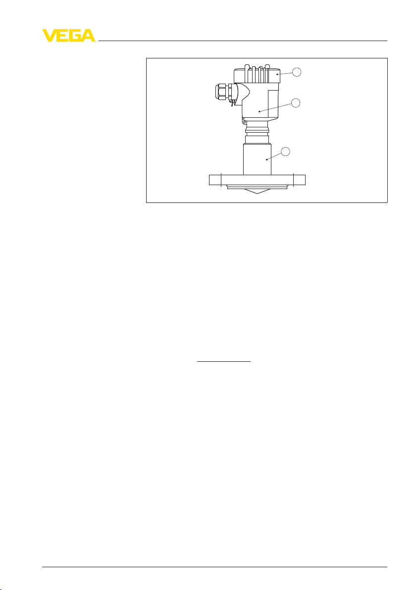
You can give your instrument additional protection against moisture
penetration by leading the connection cable downward in front of the
cable entry. Rain and condensation water can thus drain off. This
applies mainly to outdoor mounting as well as installation in areas
where high humidity is expected (e.g. through cleaning processes) or
on cooled or heated vessels.
Fig. 2: Measures against moisture
penetration
The reference plane for the measuring range of the sensors is the
lower edge of the flange.
Information:
If the
medium reaches the antenna, buildup can form on it and cause
faulty measurements later on.
Mountin
g position
Moisture
Measu
ring range
12 VEGAPULS 63 • 4 … 20 mA/HART - two-wire
4 Mounting
28436-EN-120530

1 32
100%
0%
4
Fig. 3: Measuring range (operating range) and
max. measuring distance
1 full
2 empty (max. measuring distance)
3 Measuring range
4 Reference plane
The emitted radar impulses of VEGAPULS 63 are electromagnetic
waves. The polarisation plane is the direction of the electrical share.
Their position is marked on the instrument.
1
Fig. 4: Position of the
polarisation plane of VEGAPULS 63
1 Marking hole
Make sure that all parts of the instrument exposed to the process, in
particular the sensor element, process seal and process fitting, are
suitable for the existing process conditions. These include above all
the process pressure, process temperature as well as the chemical
properties of the medium.
You can find the specifications in chapter "Technical data" and on the
type label.
Polarisation plane
Suitability for the pro-
cess condition
s
VEGAPULS 63 • 4 … 20 mA/HART - two-wire 13
4 Mounting
28436-EN-120530
4.2 Instruction
s for installation
The flange screws of VEGAPULS 63 must be always screwed with the
torque stated in the technical data so that the PTFE washer of the
encapsulated antenna system seals.
You can counteract the material-induced tension loss with PTFE by
doing the following:
1 Make sure the number of flange screws corresponds to the
number of flange holes
2 Use disc springs in addition to the flange screws for fastening the
flange
3 Tighten the screws steadily with the torque specified in the
technical data
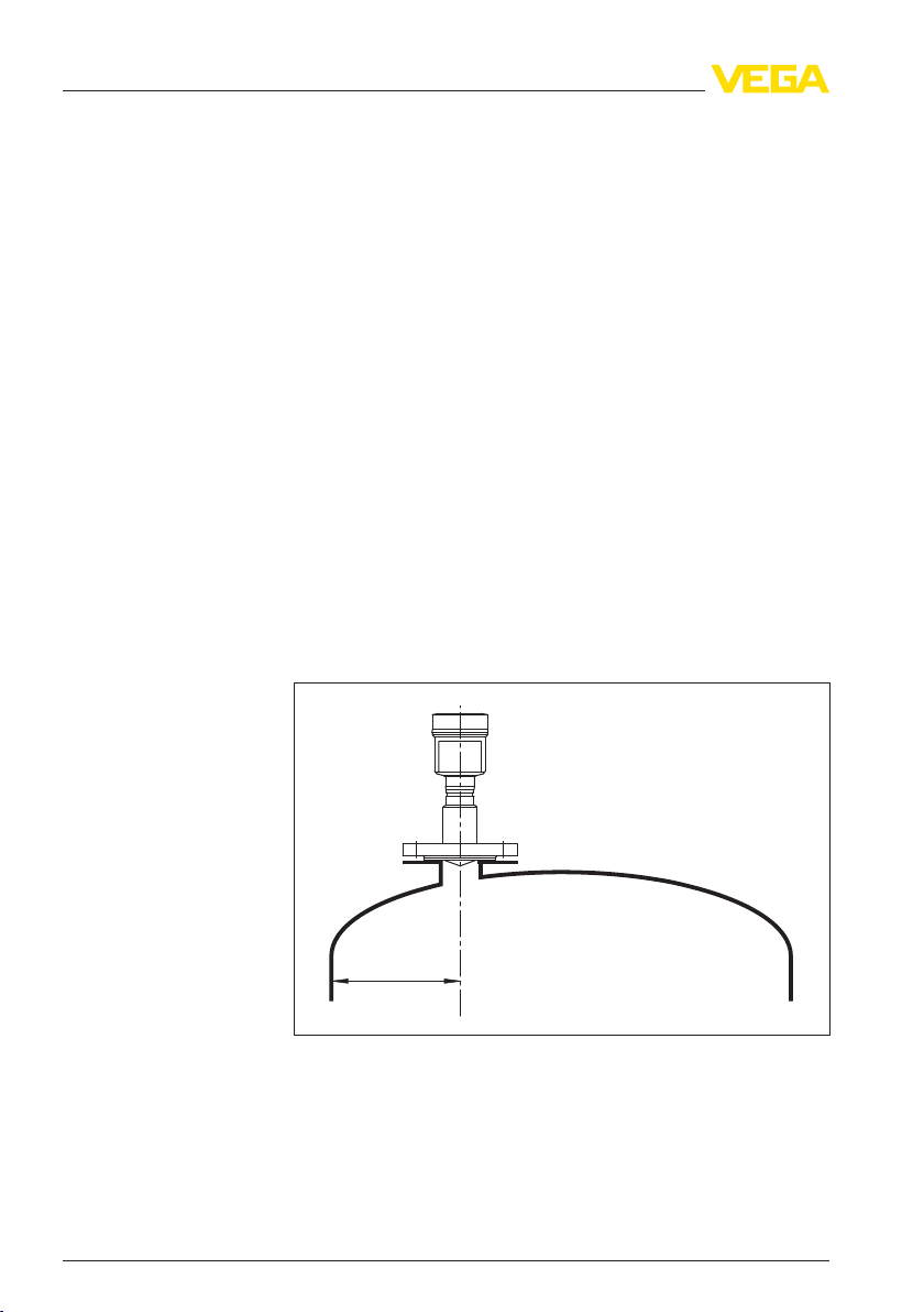
When mounting the VEGAPULS 63, keep a distance of at least
200 mm (7.874 in) to the vessel wall. If the sensor is installed in the
center of dished or round vessel tops, multiple echoes can arise.
These can, however, be suppressed by an appropriate adjustment
(see chapter "Setup").
If you cannot keep this distance you should carry out a false echo
storage before setup. This applies mainly if buildup on the vessel wall
is expected. In this case, w e recommend repeating a false echo
storage later with existing buildup.
> 200 mm
(7.87
")
Fig. 5: Mounting on round
vessel tops
1 Reference plane
2 Vessel center or symmetry axis
In vessels with conical bottom it can be advantageous to mount the
sensor in the center of the vessel, as measurement is then possible
down to the lowest point of the vessel bottom.
Mounting of instruments
with PTFE-coated flan-
ges
Mountin
g position
14 VEGAPULS 63 • 4 … 20 mA/HART - two-wire
4 Mounting
28436-EN-120530
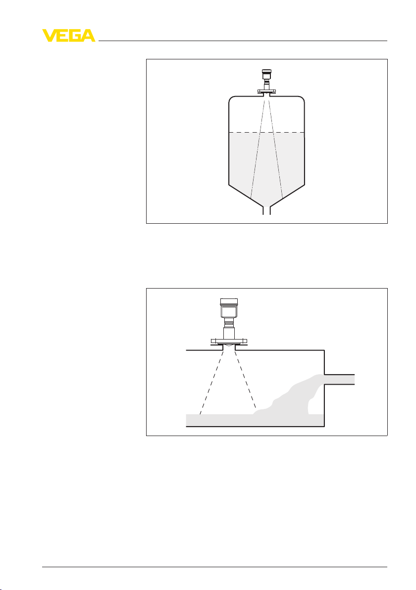
Fig. 6: Vessel with conical
bottom
Do not mount the instruments in or above the filling stream. Make sure
that you detect the product surface, not the inflowing product.
Fig. 7: Inflowing liquid
Flush
mounting
The best way to mount the sensor, also with respect to cleanability, is
flush on a block flange (flange without socket piece) or with hygienic
fittings, e.g. Neumo Biocontrol.
Mounting on socket
Inflowing medium
Soc
ket
VEGAPULS 63 • 4 … 20 mA/HART - two-wire 15
4 Mounting
28436-EN-120530
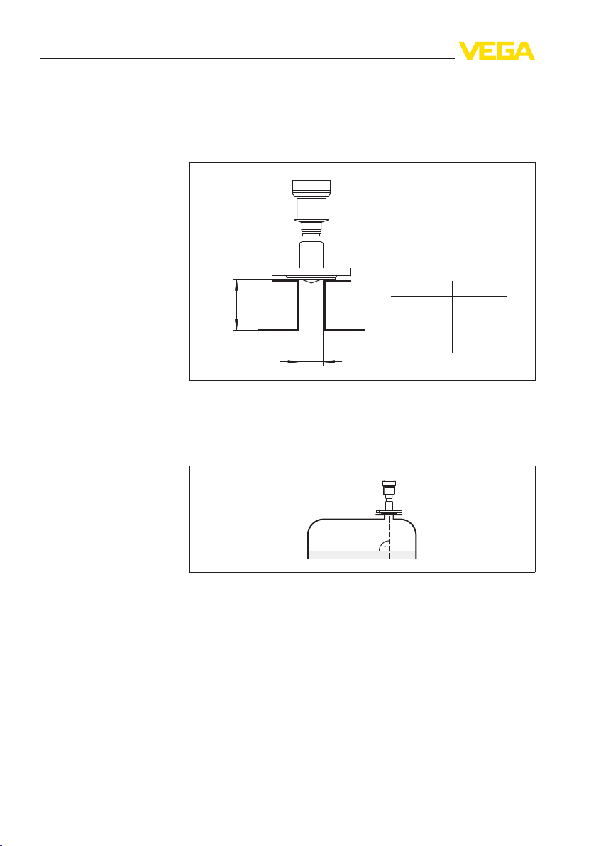
If the reflective
properties of the medium are good, you can mount
VEGAPULS 63 on a socket piece. You will find recommended values
for socket heights in the following illustration. The socket end should
be smooth and burr-free, if possible also rounded. Then carry out a
false echo storage.
d
h
max.
d
50 mm/2"
80 mm/3"
100 mm/4"
150 mm/6"
100 mm
150 mm
250 mm
400 mm
h
max.
Fig. 8: Deviating socket dimensions
Align
the sensor in liquids as vertical as possible to the product surface
to achieve optimum measurement.
Fig. 9: Alignment in liquids
Th
e mounting location of the radar sensor should be a place where no
other equipment or fixtures cross the path of the microwave signals.
Vessel installations such as for example, ladders, limit switches,
heating spirals, struts etc. can cause false echoes that interfere with
the useful echo. Make sure when planning your measuring site that the
radar signals have a "clear view" to the measured product.
In case of exis ting vessel installations, a false echo storage should be
carried out during setup.
Sen
sor orientation
Vessel installations
16 VEGAPULS 63 • 4 … 20 mA/HART - two-wire
4 Mounting
28436-EN-120530
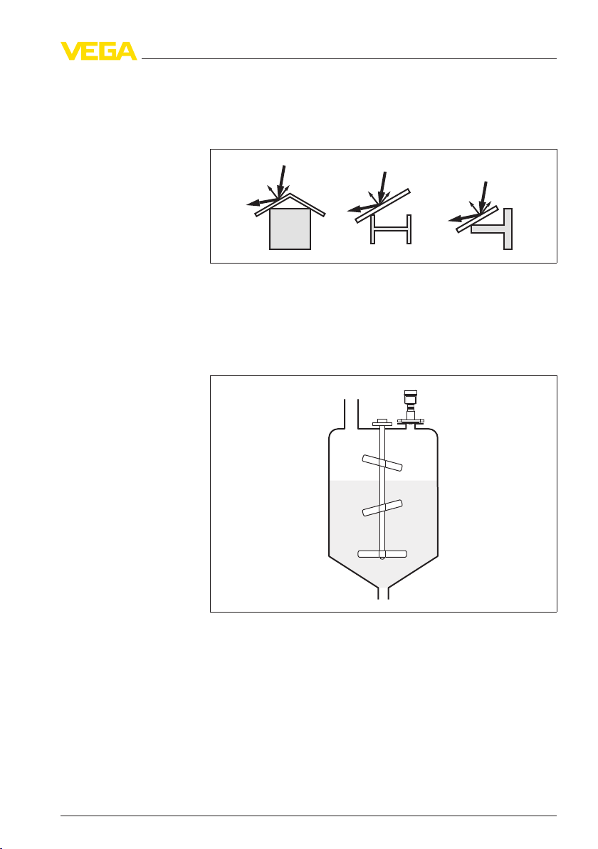
If large vessel installations such as struts or supports cause false
echoes, t
hese can be attenuated through supplementary measures.
Small, inclined sheet metal baffles above the installations scatter the
radar signals and prevent direct interfering reflections.
Fig. 10: Cover smooth profiles
with deflectors
If there are agitators in the vessel, a false signal memory should be
carried out with the agitators in motion. This ensures that the interfering
reflections from the agitators are saved with the blades in different
positions.
Fig. 11: Agitators
Through the
action of filling, stirring and other processes in the vessel,
dense foams which considerably damp the emitted signals may form
on the product surface.
If foams lead to measurement errors, you should use the biggest
possible radar antennas and low frequency radar sensors (C-band).
As an alternative, sensors with guided microwave can be used. These
are unaffected by foam generation and are best suited for such
applications.
Agitators
Foam generation
VEGAPULS 63 • 4 … 20 mA/HART - two-wire 17
4 Mounting
28436-EN-120530
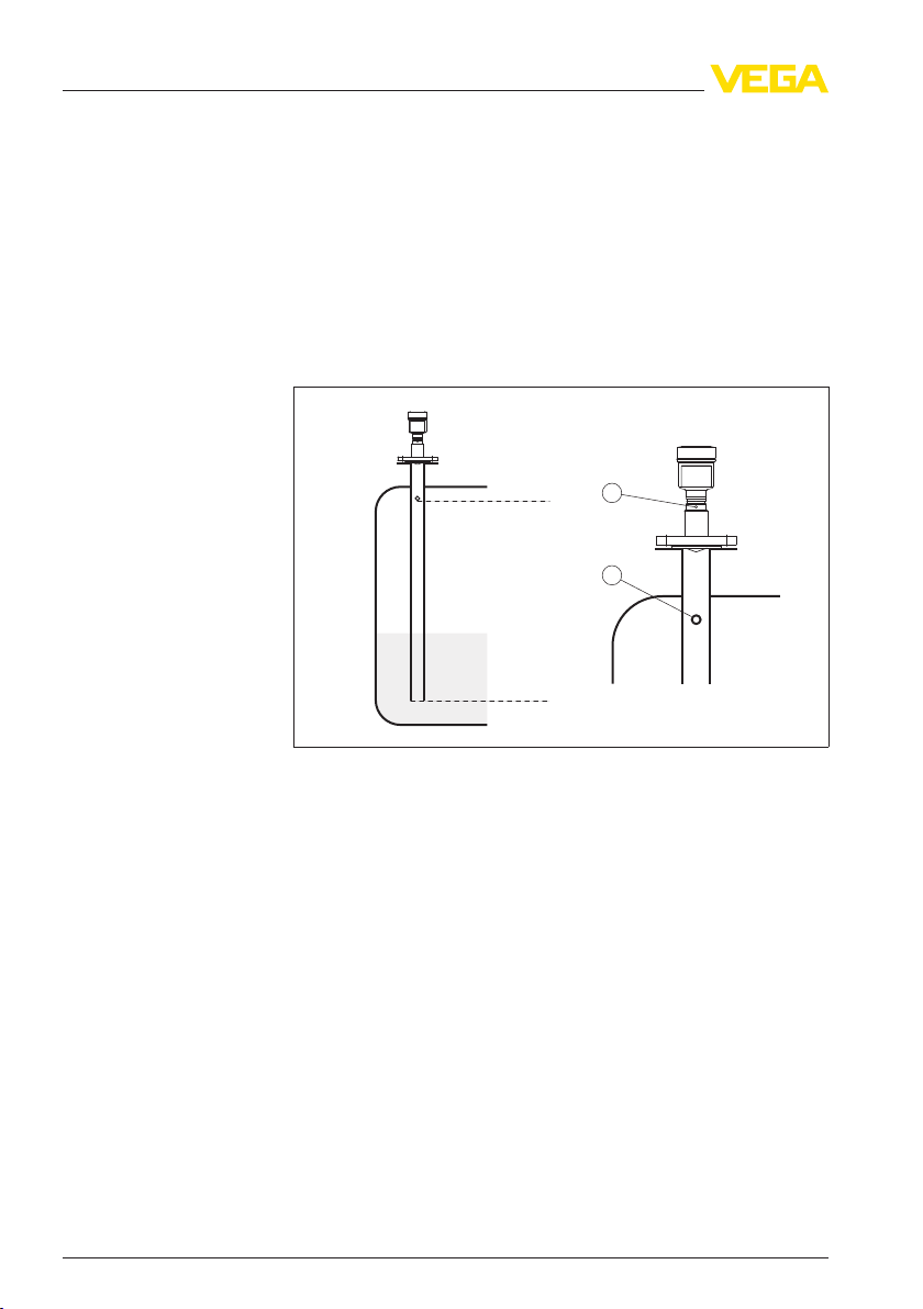
By using a standpipe, the influ
ence of vessel installations and
turbulence can be excluded. Under these prerequisites, the meas-
urement of products with low dielectric figure (from 1.6) is possible.
Surge or bypass tubes must extend all the way down to the requested
min. level, as measurement is only possible within the tube.
Surge pipe
Make sure you provide the necessary upper vent hole in the surge
pipe. The hole must be aligned so that it and the polarisation marking
on the sensor are in the same plane (see illustration: "Pipe antenna
system in a tank").
max.
min.
2
1
Fig. 12: Pipe
antenna
system
in a tank. The vent hole in the surge pipe must be
in one plane with the polarisation marking on the sensor.
1 Marking of the polarisation direction
2 Vent hole max. ø 5 mm (0.2 in)
If possible, the antenna diameter of the sensor should correspond to
the inner diameter of the tube. With VEGAPULS 63 this is approx.
40 mm (1.575 in). The sensor can be used with tube diameters
between 40 … 80 mm (1.575 … 3.15 in).
Bypass tube
As an alternative to the surge pipe in the vessel, a tube system outside
of the vessel is possible as a bypass tube. Select during setup the
function "Bypass tube".
Align the sensor in such a way that the polarisation marking on the
process fitting is in the same plane as the tube holes or the tube
connection openings (see illustration: "VEGAPULS in a bypass tube").
Measu
rement in the
standpipe (surge
or by-
pass tube)
18 VEGAPULS 63 • 4 … 20 mA/HART - two-wire
4 Mounting
28436-EN-120530
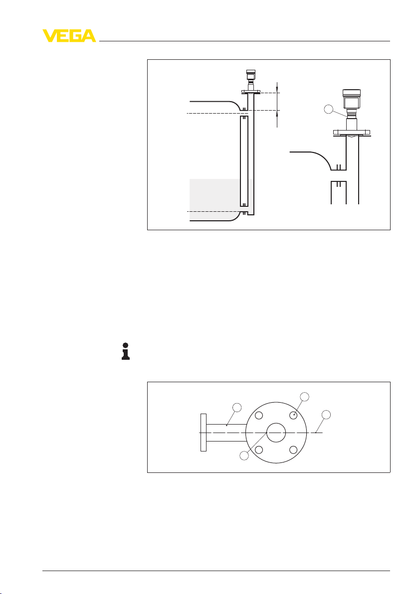
100%
0%
1
> 300 mm
Fig. 13: VEGAPULS 63 in a bypass
tube. The polarisation marking on the
process fitting must be in one plane with the tube holes or the tube connection
openings.
1 Marking of the polarisation direction
When the sensor is mounted on a bypass tube, the distance from
VEGAPULS 63 to the upper tube connection should be approx.
300 mm (11.81 in) or more. In case of extremely rough tube inner
walls, you should use an inserted tube (tube in tube) or a radar sensor
with tube antenna.
Informa
tion:
With VEG
APULS 63 in flang
e version, the polarisation plane is always
in the center between two flange holes.
1
2
3
4
Fig. 14: Polarisation level with flange
version, view from top on the sensor and
bypass tube. The sensor housing is not shown.
1 Position of the polarisation level
2 Flange hole
3 Upper tube connection
4 Polarisation marking
VEGAPULS 63 • 4 … 20 mA/HART - two-wire 19
4 Mounting
28436-EN-120530

5 Connecting to power supply
5.1 Preparin
g the connection
Always keep in mind the following safety instructions:
l Connect only in the complete absence of line voltage
l If overvoltage surges are expected, overvoltage arresters should
be installed
Tip:
We recomm
end using VEGA overvoltage arresters B63-48 and
ÜSB 62-36G.X.
In hazardous areas you must take note of the respective regulations,
conformit
y and type approval certificates of the sensors and power
supply units.
Power supply and current signal are carried on the same two-wire
cable. The voltage supply range can differ depending on the
instrument version.
The data for power supply are specified in chapter "Technical data".
Provide a reliable separation between the supply circuit and the mains
circuits according to DIN VDE 0106 part 101. The VEGA power supply
units VEGATRENN 149A Ex, VEGASTAB 690 as well as all
VEGAMETs and VEGASCANs meet this requirement.
Keep in mind the following additional factors that influence the
operating voltage:
l Output voltage of the power supply unit can be lower under
nominal load (with a sensor current of 20.5 mA or 22 mA in case of
fault message)
l Influence of additional instruments in the circuit (see load values in
chapter "Technical data")
The instrument is connected with standard two-wire cable without
screen. If electromagnetic interference is expected which is above the
test values of EN 61326 for industrial areas, screened cable should be
used.
Use cable with round cross-section. A cableouterdiameter of 5 … 9 mm
(0.2 … 0.35 in) ensures the seal effect of the cable gland. If you are
using cable with a different diameter or cross-section, exchange the
seal or use a suitable cable gland.
We generally recommend the use of screened cable for HART
multidrop mode.
On the instrument with cable entry ½ NPT and plastic housing there is
a metallic ½" threaded insert moulded into the plastic housing.
Safety instructions
Voltage supply
Connection cable
Cable gland ½ NPT
20 VEGAPULS 63 • 4 … 20 mA/HART - two-wire
5 Connecting to power supply
28436-EN-120530

Caution:
No greas
e should be used when screwing the NPT cable gland or
steel tube into the threaded insert. Standard grease can contain
additives that corrode the connection between threaded insert and
housing. This would influence the stability of the connection and the
tightness of the housing.
If screened cable is necessary, connect the cable screen on both ends
to ground potential. In the sensor, the screen must be connected
directly to the internal ground terminal. The ground terminal on the
outside of the housing must be connected to the potential equalisation
(low impedance).
If potential equalisation currents are expected, the connection on the
processing side must be made via a ceramic capacitor (e. g. 1 nF,
1500 V). The low frequency potential equalisation currents are thus
suppressed, but the protective effect against high frequency interfer-
ence signals remains.
Warning:
Within galvan
ic plants as well as vessels with cathodic corrosion
protection there are considerable potential differences. Considerably
equalisation currents can be caused via the cable scrren when the
screen is earthed on both ends. To avoid this, the cable screen must
only connected to ground potential on one side of the switching
cabinet in such applications. The cable screen must not be connected
to the internal ground terminal in the sensor and the outer ground
terminal on the housing not to the potential equalisation!
Informa
tion:
Th
e
metallic parts of the instrument (transmitter, process fitting, etc.)
are conductively connected with the inner and outer ground terminal
on the housing. This connection exists either as a direct metallic
contact or via the shielding of the special connection cable on
instruments with external electronics. You can find specifications on
the potential connections within the instrument in chapter "Technical
data".
Take note of the corresponding installation regulations for Ex
appl
ications. In particular, make sure that no potential equalisation
currents flow over the cable screen. In case of groundingon both sides
this can be achieved by the use of a capacitor or a separate potential
equalisation.
5.2 Connection procedure
Proceed as follows:
1 Unscrew the housing cover
Cable
screening and
grounding
VEGAPULS 63 • 4 … 20 mA/HART - two-wire 21
5 Connecting to power supply
28436-EN-120530
Loading...