


 Loading...
Operating Instructions
Radiation-based sensor for density measurement
MINITRAC 31
4 … 20 mA/HART - four-wire
Document ID: 40447

Contents
Contents
1 About this document |
4 |
|
1.1 |
Function............................................................................................................................ |
|
1.2 |
Target group...................................................................................................................... |
4 |
1.3 |
Symbolism used............................................................................................................... |
4 |
2 For your safety |
5 |
|
2.1 |
Authorised personnel........................................................................................................ |
|
2.2 |
Appropriate use................................................................................................................ |
5 |
2.3 |
Warning about incorrect use............................................................................................. |
5 |
2.4 |
General safety instructions................................................................................................ |
5 |
2.5 |
CE conformity................................................................................................................... |
6 |
2.6 |
NAMUR recommendations............................................................................................... |
6 |
2.7 |
Environmental instructions................................................................................................ |
6 |
3 Product description |
7 |
|
3.1 |
Configuration.................................................................................................................... |
|
3.2 |
Principle of operation........................................................................................................ |
8 |
3.3 |
Packaging, transport and storage................................................................................... |
10 |
3.4 |
Accessories and replacement parts................................................................................ |
10 |
3.5 |
Corresponding source container..................................................................................... |
11 |
4 |
Mounting |
13 |
||
|
4.1 |
General instructions........................................................................................................ |
||
|
4.2 |
Mounting instructions...................................................................................................... |
14 |
|
5 |
Connecting to power supply |
20 |
||
|
5.1 |
Preparing the connection................................................................................................ |
||
|
5.2 |
Connection - Density, mass flow rate measurement....................................................... |
23 |
|
|
5.3 |
Connection - Level detection........................................................................................... |
26 |
|
6 |
Set up with the display and adjustment module |
28 |
||
|
6.1 |
Insert display and adjustment module............................................................................. |
||
|
6.2 |
Adjustment system.......................................................................................................... |
29 |
|
|
6.3 |
Parameter adjustment - Level measurement................................................................... |
29 |
|
|
6.4 |
Parameter adjustment - Density measurement............................................................... |
34 |
|
|
6.5 |
Parameter adjustment - Point level detection.................................................................. |
47 |
|
|
6.6 |
Parameter adjustment - X-ray alarm................................................................................ |
56 |
|
|
6.7 |
Parameter adjustment/Real value correction.................................................................. |
58 |
|
|
6.8 |
Saving the parameter adjustment data........................................................................... |
60 |
|
7 |
Setup with PACTware |
61 |
||
|
7.1 |
Connect the PC............................................................................................................... |
||
|
7.2 |
Parameter adjustment with PACTware............................................................................ |
62 |
|
|
7.3 |
Saving the parameter adjustment data........................................................................... |
63 |
|
8 |
Set up with other systems |
64 |
||
|
8.1 |
DD adjustment programs................................................................................................ |
||
|
8.2 |
Field Communicator 375, 475......................................................................................... |
64 |
|
9 |
Diagnostics and service |
65 |
||
|
9.1 |
Maintenance................................................................................................................... |
||
|
9.2 |
Status messages............................................................................................................ |
65 |
|
|
9.3 |
Rectify faults................................................................................................................... |
69 |
|
|
|
|
|
|
2 |
|
MINITRAC 31 • 4 … 20 mA/HART - four-wire |
||
131119-EN-40447

40447-EN-131119
|
|
Contents |
9.4 |
Exchanging the electronics module |
................................................................................ 71 |
9.5 |
Software update.............................................................................................................. |
71 |
9.6 |
How to proceed in case of repair..................................................................................... |
71 |
10 Dismounting |
|
|
10.1 |
Dismounting steps.......................................................................................................... |
73 |
10.2 |
Disposal.......................................................................................................................... |
73 |
11 Supplement |
|
|
11.1 |
Technical data................................................................................................................. |
74 |
11.2 |
Dimensions..................................................................................................................... |
79 |
Safety instructions for Ex areas
Please note the Ex-specific safety information for installation and operation in Ex areas. These safety instructions are part of the operating instructions manual and come with the Ex-approved instruments.
Editing status: 2013-11-11
MINITRAC 31 • 4 … 20 mA/HART - four-wire |
3 |

1 About this document
1 About this document
1.1Function
This operating instructions manual provides all the information you need for mounting, connection and setup as well as important instructions for maintenance and fault rectification.Please read this information before putting the instrument into operation and keep this manual accessible in the immediate vicinity of the device.
1.2Target group
This operating instructions manual is directed to trained specialist personnel. The contents of this manual should be made available to these personnel and put into practice by them.
1.3Symbolism used
•
→
Information, tip, note
This symbol indicates helpful additional information.
Caution: If this warning is ignored, faults or malfunctions can result.
Warning: If this warning is ignored, injury to persons and/or serious damage to the instrument can result.
Danger: If this warning is ignored, serious injury to persons and/or destruction of the instrument can result.
Ex applications
This symbol indicates special instructions for Ex applications.
List
The dot set in front indicates a list with no implied sequence.
Action
This arrow indicates a single action.
1Sequence of actions
Numbers set in front indicate successive steps in a procedure.
Battery disposal
This symbol indicates special information about the disposal of batteries and accumulators.
131119-EN-40447
4 |
MINITRAC 31 • 4 … 20 mA/HART - four-wire |

40447-EN-131119
2 For your safety
2 For your safety
2.1Authorised personnel
All operations described in this operating instructions manual must be carried out only by trained specialist personnel authorised by the plant operator.
During work on and with the device the required personal protective equipment must always be worn.
2.2Appropriate use
The MINITRAC 31 is a sensor for density measurement and level detection.
You can find detailed information on the application range in chapter
"Product description".
Operational reliability is ensured only if the instrument is properly used according to the specifications in the operating instructions manual as well as possible supplementary instructions.
2.3Warning about incorrect use
Inappropriate or incorrect use of the instrument can give rise to application-specific hazards, e.g.vessel overfill or damage to system components through incorrect mounting or adjustment.
2.4General safety instructions
This is a state-of-the-art instrument complying with all prevailing regulations and guidelines. The instrument must only be operated in a technically flawless and reliable condition.The operator is responsible for the trouble-free operation of the instrument.
During the entire duration of use, the user is obliged to determine the compliance of the necessary occupational safety measures with the current valid rules and regulations and also take note of new regulations.
The safety instructions in this operating instructions manual, the national installation standards as well as the valid safety regulations and accident prevention rules must be observed by the user.
For safety and warranty reasons, any invasive work on the device beyond that described in the operating instructions manual may be carried out only by personnel authorised by the manufacturer. Arbitrary conversions or modifications are explicitly forbidden.
The safety approval markings and safety tips on the device must also be observed.
This measuring system uses gamma rays. Therefore take note of the instructions for radiation protection in chapter "Product description". All work on the source container may only be carried out under the supervision of a qualified radiation protection officer.
MINITRAC 31 • 4 … 20 mA/HART - four-wire |
5 |

2 For your safety
2.5CE conformity
The device fulfills the legal requirements of the applicable EC guidelines.By affixing the CE marking,VEGA confirms successful testing of the product.
Only with class A instruments:
The device is a class A instrument designed for use in an industrial environment.When used in a different environment, e.g., in a living area, the electromagnetic compatibility must be ensured by the user. If necessary, suitable screening measures against conducted and emitted disturbances must be taken.
You can find the conformity certificate in the download section under www.vega.com.
2.6NAMUR recommendations
NAMUR is the automation technology user association in the process industry in Germany. The published NAMUR recommendations are accepted as the standard in field instrumentation.
The device fulfills the requirements of the following NAMUR recommendations:
•
•
•
•
NE 21 – Electromagnetic compatibility of equipment
NE 43 – Signal level for malfunction information from measuring transducers
NE 53 – Compatibility of field devices and display/adjustment components
NE 107 – Self-monitoring and diagnosis of field devices
For further information see www.namur.de.
2.7Environmental instructions
Protection of the environment is one of our most important duties. That is why we have introduced an environment management system with the goal of continuously improving company environmental protection.The environment management system is certified according to DIN EN ISO 14001.
Please help us fulfill this obligation by observing the environmental instructions in this manual:
•Chapter "Packaging, transport and storage"
•Chapter "Disposal"
131119-EN-40447
6 |
MINITRAC 31 • 4 … 20 mA/HART - four-wire |

40447-EN-131119
3 Product description
3 Product description
3.1Configuration
Type plate |
The nameplate contains the most important data for identification and |
|
use of the instrument: |
1 |
2 |
3 |
9 |
4 |
|
5 |
8 |
6 |
7 |
Fig. 1: Layout of the type label (example)
1Instrument type
2Product code
3Electronics
4Protection rating
5Ambient temperature
6Hardware and software version
7Order number
8Serial number of the instrument
9ID numbers, instrument documentation
Serial number |
The type label contains the serial number of the instrument. With it |
|
you can find the following data on our homepage: |
•Product code of the instrument (HTML)
•Delivery date (HTML)
•Order-specific instrument features (HTML)
•Operating instructions at the time of shipment (PDF)
•Order-specific sensor data for an electronics exchange (XML)
•Test certificate pressure transmitters (PDF)
Go to www.vega.com, "VEGA Tools" and "Serial number search".
As an alternative, you can find the data via your Smartphone:
•Download the smartphone app "VEGA Tools" from the "Apple App Store" or the "Google Play Store"
•Scan the Data Matrix code on the type label of the instrument or
•Enter the serial number manually in the app
Scope of this operating |
This operating instructions manual applies to the following instrument |
instructions manual |
versions: |
•Hardware from 1.0.4
•Software from 1.4.2
•Modification status, electronics as of -01
MINITRAC 31 • 4 … 20 mA/HART - four-wire |
7 |

3 Product description
Electronics versions |
The instrument is available in different electronics versions.Each ver- |
||
|
sion can be identified via the product code on the type label: |
||
|
• |
Standard electronics type PT30E-XX |
|
Scope of delivery |
The scope of delivery encompasses: |
||
|
• |
Radiation-based sensor |
|
|
• |
Mounting accessory |
|
|
• |
Documentation |
|
|
–– |
this operating instructions manual |
|
|
|
–– Operating instructions manual "Display and adjustment mod- |
|
|
|
–– |
ule" (optional) |
|
|
Ex-specific "Safety instructions" (with Ex versions) |
|
|
|
–– |
if necessary, further certificates |
|
3.2 |
Principle of operation |
|
Application area |
The instrument is suitable for applications in liquids and bulk solids in |
||
|
vessels under difficult process conditions.There are application pos- |
||
|
sibilities in nearly all areas of industry. |
||
The measured value is detected contactlessly right through the vessel wall.Neither a process fitting nor a vessel opening are required.The instrument is thus ideal for retro installation.
The instrument can be used for many different measuring tasks.Apart from the main applications such as density measurement and level detection, the MINITRAC 31 can also detect residues and the mass flow rate in conjunction with a flow meter.
131119-EN-40447
8 |
MINITRAC 31 • 4 … 20 mA/HART - four-wire |

3 Product description
1 |
|
|
2 |
|
|
|
|
|
|
|
|
|
|
|
|
|
|
|
|
4
3
40447-EN-131119
Fig. 2: MINITRAC 31 - Application possibilities
1Level measurement - Residue detection
2Point level detection
3Density measurement
4Mass flow measurement
|
Further application possibilities are also the use as X-ray alarm or real |
|
|
value correction. |
|
|
If X-ray alarm is selected, the instrument detects radiation from exter- |
|
|
nal sources. Possible external radiation sources can be, for example, |
|
|
a weld joint test in a neighbouring facility or other radiation-based |
|
|
instruments. |
|
|
When the instrument operates as real value correction it transmits the |
|
|
real value to correct another radiation-based sensor. The measure- |
|
|
ment can thus be adapted perfectly to the situation in the vessel. |
|
Functional principle |
In radiation-based measurement, a Caesium-137 or Cobalt-60 iso- |
|
|
tope emits focussed gamma rays that are attenuated when penetrat- |
|
|
ing the tube wall and the medium. The NaI detector on the opposite |
|
|
side, on a pipeline for example, receives the radiation. The intensity |
|
|
of the radiation is dependent on the density of the measured media. |
|
|
The measuring principle has proven to be very reliable in conjunction |
|
|
with extreme process conditions because it measures contactlessly |
|
|
|
|
MINITRAC 31 • 4 … 20 mA/HART - four-wire |
9 |
|

3 Product description
|
from outside through the tube wall. The measuring system ensures |
||
|
maximum safety, reliability and plant availability independent of the |
||
|
medium and its properties. |
||
|
3.3 Packaging, transport and storage |
||
Packaging |
Your instrument was protected by packaging during transport. Its |
||
|
capacity to handle normal loads during transport is assured by a test |
||
|
based on ISO 4180. |
||
|
The packaging of standard instruments consists of environment- |
||
|
friendly, recyclable cardboard. For special versions, PE foam or PE |
||
|
foil is also used. Dispose of the packaging material via specialised |
||
|
recycling companies. |
||
Transport |
Transport must be carried out in due consideration of the notes on the |
||
|
transport packaging. Nonobservance of these instructions can cause |
||
|
damage to the device. |
||
Transport inspection |
The delivery must be checked for completeness and possible transit |
||
|
damage immediately at receipt. Ascertained transit damage or con- |
||
|
cealed defects must be appropriately dealt with. |
||
Storage |
Up to the time of installation, the packages must be left closed and |
||
|
stored according to the orientation and storage markings on the |
||
|
outside. |
||
|
Unless otherwise indicated, the packages must be stored only under |
||
|
the following conditions: |
||
|
• |
Not in the open |
|
|
• |
Dry and dust free |
|
|
• |
Not exposed to corrosive media |
|
|
• |
Protected against solar radiation |
|
|
• |
Avoiding mechanical shock and vibration |
|
Storage and transport |
• |
Storage and transport temperature see chapter "Supplement - |
|
temperature |
Technical data - Ambient conditions" |
||
|
• |
Relative humidity 20 … 85 % |
|
|
3.4 Accessories and replacement parts |
||
PLICSCOM |
The display and adjustment module PLICSCOM is used for measured |
||
|
value indication, adjustment and diagnosis. It can be inserted into the |
||
|
sensor or the external display and adjustment unit and removed at |
||
|
any time. |
||
|
You can find further information in the operating instructions "Display |
||
|
and adjustment module PLICSCOM" (Document-ID 27835). |
||
VEGACONNECT |
The interface adapterVEGACONNECT enables the connection of |
||
|
communication-capable instruments to the USB interface of a PC. For |
||
|
parameter adjustment of these instruments, the adjustment software |
||
|
PACTware withVEGA-DTM is required. |
||
|
You can find further information in the operating instructions "Interface |
||
|
adapter VEGACONNECT" (Document-ID 32628). |
||
|
|
|
|
10 |
|
MINITRAC 31 • 4 … 20 mA/HART - four-wire |
|
131119-EN-40447
|
|
3 Product description |
VEGADIS 81 |
TheVEGADIS 81 is an external display and adjustment unit forVEGA |
|
|
|
plics® sensors. |
|
|
For sensors with double chamber housing the interface adapter "DIS- |
|
|
ADAPT" is also required forVEGADIS 81. |
|
|
You can find further information in the operating instructions "VE- |
|
|
GADIS 81" (Document-ID 43814). |
External indicating unit |
TheVEGADIS 62 is suitable for measured value indication of sensors. |
|
|
|
It is looped into the 4 … 20 mA/HART signal cable. |
|
|
You can find further information in the operating instructions "VE- |
|
|
GADIS 62" (Document-ID 36469). |
Electronics module |
The electronics module PT30E.XX is a replacement part for radiation- |
|
|
|
based sensors MINITRAC 31. |
|
|
The electronics module can only be exchanged byVEGA service |
|
|
technician. |
Mounting accessory |
For mounting MINITRAC 31 holders as well as special mounting ac- |
|
|
|
cessories are available. Please contact our sales department. |
|
|
3.5 Corresponding source container |
|
|
A radioactive isotope in a suitable source holder is the prerequisite for |
|
|
a radiation-based measurement setup. |
|
|
The handling of radioactive substances is regulated by law. The radia- |
|
|
tion protection rules of the country in which the system is operated |
|
|
apply first and foremost. |
|
|
In Germany, for example, the current radiation protection ordinance |
|
|
(StrlSchV) based on the Atomic Energy Law (AtG) applies. |
|
|
The following points are important for measurement with radiation- |
|
|
based methods: |
Handling permit |
A handling permit is required for operation of a system using gamma |
|
|
|
rays.This permit is issued by the respective government office or the |
|
|
responsible authority (in Germany, for example, offices for environ- |
|
|
mental protection, trade supervisory boards, etc.) |
|
|
You can find further instructions in the operating instructions manual |
|
|
of the source container. |
General instructions for |
When handling radioactive sources, unnecessary radiation exposure |
|
radiation protection |
must be avoided. An unavoidable radiation exposure must be kept as |
|
|
|
low as possible. Take note of the following three important measures: |
40447-EN-131119
MINITRAC 31 • 4 … 20 mA/HART - four-wire |
11 |

3 Product description
|
|
|
1 |
2 |
3 |
|
|
|
|
||
|
Fig. 3: Measures for protection against radioactive radiation |
|
|||
|
1 |
Shielding |
|
|
|
|
2 |
Time |
|
|
|
|
3 |
Distance |
|
|
|
|
Shielding: Provide good shielding between the radioactive source |
||||
|
and yourself as well as all other persons. Special source containers |
||||
|
(e.g.VEGASOURCE) as well as all materials with high density (e.g. |
||||
|
lead, iron, concrete, etc.) provide effective shielding. |
|
|||
|
Time: Stay as short a time as possible in radiation exposed areas. |
||||
|
Distance:Your distance to the source should be as large as possible. |
||||
|
The local dose rate of the radiation decreases in proportion to the |
||||
|
square of the distance to the radiation source. |
|
|||
Radiation safety officer |
The plant operator must appoint a radiation safety officer with the |
||||
|
necessary expert knowledge. He is responsible that the radiation |
||||
|
protection ordinance is maintained and that all radiation protection |
||||
|
measures are implemented. |
|
|
||
Control area |
Control areas are areas in which the local dose rate exceeds a certain |
||||
|
value.Only persons who undergo official dose monitoring are allowed |
||||
|
into these control areas.You can find the respectively valid limit values |
||||
for control areas in the guideline of the respective authority (in Germany, for example, the radiation protection ordinance).
We are at your disposal for further information concerning radiation protection and regulations in other countries.
131119-EN-40447
12 |
MINITRAC 31 • 4 … 20 mA/HART - four-wire |

40447-EN-131119
|
|
|
4 Mounting |
|
|
|
4 |
Mounting |
|
|
|
4.1 General instructions |
||
Switch off source |
The source container is part of the measuring system. In case the |
|||
|
|
source container is already equipped with an active isotope, the |
||
|
|
source container must be locked before mounting. |
||
|
|
Danger: |
||
|
|
Before mounting; make sure that the source is securely closed. Use |
||
|
|
a padlock to secure the source container in the closed condition and |
||
|
|
prevent it from being inadvertently opened. |
||
Protection against mois- |
Protect your instrument against moisture penetration through the fol- |
|||
ture |
lowing measures: |
|||
|
|
• |
Use the recommended cable (see chapter "Connecting to power |
|
|
|
supply") |
||
|
|
• |
Tighten the cable gland |
|
|
|
• |
Loop the connection cable downward in front of the cable gland |
|
|
|
This applies particularly to: |
||
|
|
• |
Outdoor mounting |
|
|
|
• |
Installations in areas where high humidity is expected (e.g. through |
|
|
|
cleaning processes) |
||
|
|
• |
Installations on cooled or heated vessels |
|
Suitability for the process |
Make sure that all parts of the instrument exposed to the process are |
|||
conditions |
suitable for the existing process conditions. |
|||
|
|
These are mainly: |
||
|
|
• |
Active measuring component |
|
|
|
• |
Process fitting |
|
|
|
• |
Process seal |
|
|
|
Process conditions are particularly: |
||
|
|
• |
Process pressure |
|
|
|
• |
Process temperature |
|
|
|
• |
Chemical properties of the medium |
|
|
|
• |
Abrasion and mechanical influences |
|
|
|
You can find the specifications of the process conditions in chapter |
||
|
|
"Technical data" as well as on the nameplate. |
||
Protective caps |
In the case of instrument housings with self-sealing NPT threads, it is |
|||
|
|
not possible to have the cable entries screwed in at the factory. The |
||
|
|
openings for the cable glands are therefore covered with red protec- |
||
|
|
tive caps as transport protection. |
||
Prior to setup you have to replace these protective caps with approved cable glands or close the openings with suitable blind plugs.
The suitable cable glands and blind plugs come with the instrument.
MINITRAC 31 • 4 … 20 mA/HART - four-wire |
13 |

4 Mounting
4.2Mounting instructions
Installation position |
|
|
Note: |
|
|
|
|
|
Along with the planning, our specialists will analyse the conditions of |
|
|
|
|
the measurement loop to dimension the radiation source (isotope) |
|
|
|
|
|
|
|
|
|
accordingly. |
You get a "Source Sizing" document specifying the required source activity and containing all relevant mounting information for your measuring point.
You must follow the instructions of this "Source Sizing" document in addition to the following mounting instructions.
The following mounting information is applicable as long as there is nothing else specified in the "Source Sizing" document.
You can find information on protective barriers and the mounting of the corresponding source container in the operating instructions manual of the source container, e.g.VEGASOURCE.
You can mount the MINITRAC 31 in any position. If you have ordered your instrument with a lead cover as a protection against ambient radiation (optionally), the the sensor is shielded laterally against X-ray radiation. In this case, the radiation can only penetrate frontally.
Fasten the sensors in such a way that they cannot fall out of the holder.
Direct the exit angle of the source container to the MINITRAC 31.
Mount the source container as close as possible to the vessel. If there are gaps, secure the area with a safety fence and protective grating so that no one can reach into the dangerous area.
Caution:
Make sure that the tube is always completely filled.Mainly in horizontally arranged tube measuring distances, air bubbles or buildup in the tube can influence the measuring result.Measurement should be preferably through the centre of the tube.
131119-EN-40447
14 |
MINITRAC 31 • 4 … 20 mA/HART - four-wire |

4 Mounting
1 |
2 |
Fig. 4: Installation on a horizontal pipeline
1Air bubbles
2Buildup
Density measurement
A density and concentration measurement is possible on pipelines and vessels. The accuracy of the measurement increases in proportion to the radiated length (L) of medium. This is particularly important in the case of products with low density or small tube diameters.
There are different ways to increase the radiated length (L) of the medium.
40447-EN-131119
MINITRAC 31 • 4 … 20 mA/HART - four-wire |
15 |

4 Mounting
1 |
|
2 |
|
|
a |
|
L |
L |
|
|
|
|
|
b |
|
|
4 |
|
|
L |
|
3 |
|
Fig. 5: Installation possibilities - Density measurement or concentration measurement
1a Radial raditiona - vertical mounting
1b Axial radiation - Horizontal mounting or when the lead cover is used as protection against ambient radiation
2Inclined radiation for extention of the radiated length (L)
3Extension of the radiated length (L) by adding a tube angle piece as measuring distance
4Integrated lead cover as protection against ambient radiation - the instrument is hence shielded laterally
With density measurement, the radiation difference with differing density is very low. Especially with small tube diameters, the change is negligible.
Therefore it is important to shield from interfering X-ray radiation. To protect the instrument against X-ray radiation, it can be be equipped
16 |
MINITRAC 31 • 4 … 20 mA/HART - four-wire |
131119-EN-40447

4 Mounting
with an optional lead ring.A later retrofitting of the lead ring is not possible.
Mass flow rate
The mass flow rate can be determined with the MINITRAC 31 in conjunction with a flow meter.
2
1
Fig.6:Mass flow rate measurement
1Flow meter
2MINITRAC 31
Point level detection
For level detection, the sensor is generally mounted horizontally at the height of the requested limit level. Make sure that there are no struts or reinforcements at this position in the vessel.
Direct the exit beam of the source container exactly towards the measuring range of MINITRAC 31.
40447-EN-131119
MINITRAC 31 • 4 … 20 mA/HART - four-wire |
17 |
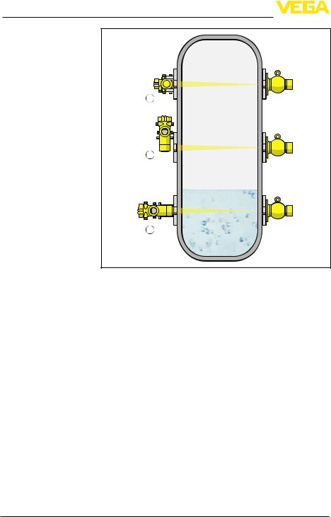
4 Mounting
3
2
1
Fig. 7: Mounting position - level detection
1Horizontal mounting
2Vertical mounting
3Mounting horizontally, at right angles to container
Level measurement - Residue detection
The MINITRAC 31 can be used for residue detection, e.g. in storage tanks for high-cost liquids. For this purpose, the instrument must be mounted at the lowest point of the vessel.
131119-EN-40447
18 |
MINITRAC 31 • 4 … 20 mA/HART - four-wire |

4 Mounting
Fig. 8: Level measurement - Residue detection on a storage tank
Protection against heat If the max. ambient temperature is exceeded, you must take suitable measures to protect the instrument against overheating.
You can protect the instrument by providing a suitable insulation against the heat or mounting the instrument further away from the heat source.
Make sure these measures are taken into account already in the planning stage. If you want to carry out such measures later on, contact our specialists to ensure that the accuracy of the application is not impaired.
If these measures are not sufficient to maintain the max.ambient temperature, you could consider using the water cooling system we offer for MINITRAC 31.
The water cooling must also be included in the calculations for the measuring point. Contact our specialists regarding the dimensioning of the water cooling.
40447-EN-131119
MINITRAC 31 • 4 … 20 mA/HART - four-wire |
19 |

5 Connecting to power supply
|
5 |
Connecting to power supply |
|
|
5.1 Preparing the connection |
||
Safety instructions |
Always keep in mind the following safety instructions: |
||
|
• |
Connect only in the complete absence of line voltage |
|
|
• |
If overvoltage surges are expected, overvoltage arresters should |
|
|
|
be installed |
|
Voltage supply via mains |
In this case, the instrument is designed in protection class II. To main- |
||
voltage |
tain this protection class, it is absolutely necessary that the ground |
||
|
conductor be connected to the internal ground terminal. Take note of |
||
|
the general installation regulations. |
||
|
Supply voltage and current signal are carried on separate connection |
||
|
cables if reliable separation is required. The supply voltage range can |
||
|
differ depending on the instrument version. |
||
|
The data for power supply are specified in chapter "Technical data". |
||
Select connection cable |
For power supply, an approved installation cable with PE conductor is |
||
|
required. |
||
|
The 4 … 20 mA current output is connected with standard two-wire |
||
|
cable without screen. If electromagnetic interference is expected |
||
|
which is above the test values of EN 61326-1 for industrial areas, |
||
|
screened cable should be used. |
||
|
Use cable with a round wire cross section. An outer cable diameter |
||
|
of 6 … 12 mm (0.24 … 0.47 in) ensures the seal effect of the cable |
||
|
entry.If cable with a different diameter or wire cross section is used, |
||
|
exchange the seal or use an appropriate cable connection. Unused |
||
|
cable entry glands do not provide sufficient protection against mois- |
||
|
ture and must be replaced with blind plugs. |
||
Cable entry |
Generally provide all unused cable entries with suitable blind plugs. |
||
|
The thin foam rubber washers in the cable glands only serve as a |
||
|
dust cover during transport. |
||
Cable gland ½ NPT |
In the case of instrument housings with self-sealing NPT threads, it |
||
|
is generally not possible to have the cable glands screwed in at the |
||
|
factory. The openings for the cable glands are therefore covered with |
||
|
red protective caps as transport protection. |
||
|
Before setup you have to replace these protective caps with approved |
||
|
cable glands or close the openings with suitable blind plugs. Unused |
||
|
cable glands do not provide sufficient protection against moisture and |
||
|
must be replaced with blind plugs. |
||
|
The suitable cable glands and blind plugs come with the instrument. |
||
Cable screening and |
If screened cable is necessary, connect the cable screen on both |
||
grounding |
ends to ground potential. In the sensor, the screen must be connected |
||
|
directly to the internal ground terminal. The ground terminal on the |
||
|
outside of the housing must be connected to the potential equalisa- |
||
|
tion (low impedance). |
||
|
|
|
|
20 |
|
MINITRAC 31 • 4 … 20 mA/HART - four-wire |
|
131119-EN-40447
5 Connecting to power supply
|
|
|
|
If potential equalisation currents are expected, the connection on the |
|
|
|
|
processing side must be made via a ceramic capacitor (e. g. 1 nF, |
|
|
|
|
1500V).The low-frequency potential equalisation currents are thus |
|
|
|
|
suppressed, but the protective effect against high frequency interfer- |
|
|
|
|
ence signals remains. |
|
|
|
|
Warning: |
|
|
|
|
Significant potential differences exist inside galvanization plants as |
|
|
|
|
well as on vessels with cathodic corrosion protection. Considerable |
|
|
|
|
equalisation currents can flow over the cable screen if the screen is |
|
|
|
|
grounded on both ends. |
|
|
|
|
To avoid this, the cable screen in such applications must be con- |
|
|
|
|
nected only on one end to ground potential in the switching cabinet. |
|
|
|
|
The cable screen must not be connected to the inner ground terminal |
|
|
|
|
in the sensor and the outer ground terminal on the housing must not |
|
|
|
|
be connected to potential equalization! |
|
|
|
|
Information: |
|
|
|
|
The metal parts of the instrument are conductively connected with |
|
|
|
|
the inner and outer ground terminal on the housing. This connection |
|
|
|
|
is either a direct metallic connection or, in case of instruments with |
|
|
|
|
external electronics, a connection via the screen of the special con- |
|
|
|
|
nection cable. |
|
|
|
|
You can find specifications on the potential connections inside the |
|
|
|
|
instrument in chapter "Technical data". |
Connection technology |
|
The voltage supply and signal output are connected via the spring- |
||
|
|
|
|
loaded terminals in the housing. |
|
|
|
|
The connection to the display and adjustment module or to the inter- |
|
|
|
|
face adapter is carried out via contact pins in the housing. |
Connection procedure |
|
Proceed as follows: |
||
|
|
|
|
The procedure applies to instruments without explosion protection. |
|
|
|
|
1. Unscrew the big housing cover |
|
|
|
|
2. Loosen compression nut of the cable entry |
|
|
|
|
3. Remove approx. 10 cm (4 in) of the cable mantle, strip approx. |
|
|
|
|
1 cm (0.4 in) of insulation from the ends of the individual wires |
|
|
|
|
4. Insert the cable into the sensor through the cable entry |
40447-EN-131119
MINITRAC 31 • 4 … 20 mA/HART - four-wire |
21 |

5 Connecting to power supply
1 |
Fig. 9: Connection steps 4 and 5 1 Locking of the terminal blocks
5.Insert a small slotted screwdriver firmly into the rectangular lock openings of the respective connection terminal
6.Insert the wire ends into the round openings of the terminals according to the wiring plan
Information:
Solid cores as well as flexible cores with cable end sleeves are inserted directly into the terminal openings.In case of flexible cores without end sleeves, press the rectangular lock opening with a small screwdriver; the terminal opening is freed. When the screwdriver is released, the terminal opening closes again.
7.Check the hold of the wires in the terminals by lightly pulling on them
To loosen a line, insert a small slotted screwdriver firmly into the rectangular locking opening according to the illustration
8.Connect the screen to the internal ground terminal, connect the outer ground terminal to potential equalisation
9.Tighten the compression nut of the cable entry gland. The seal ring must completely encircle the cable
10.Screw the housing cover back on
The electrical connection is hence finished.
22 |
MINITRAC 31 • 4 … 20 mA/HART - four-wire |
131119-EN-40447

Electronics and connection compartment
- Non-Ex instruments and instruments with nonintrinsically safe current output
5 Connecting to power supply
Information:
The terminal blocks are pluggable and can be detached from the electronics. For this purpose loosen the two lateral locking levers of the terminal block with a small screwdriver. When loosening the locking, the terminal block is automatically squeezed out.It must snap in place when re-inserted.
5.2Connection - Density, mass flow rate measurement
Non-Ex instruments and instruments with non-intrinsically safe current output
|
|
|
|
|
|
10 |
|
1 |
/L |
|
1 |
22 1 |
22 |
|
|
/N |
|
2 |
|
21 |
9 |
|
|
|
|
|
|
||||
|
PE |
|
|
|
20 |
|
|
|
|
|
|
|
|
||
|
|
|
4 |
|
19 |
|
|
|
2 |
|
5 |
|
18 |
8 |
|
|
|
|
6 |
|
17 |
|
|
|
|
|
|
|
|
||
|
|
|
|
|
16 |
6 |
|
|
|
|
|
|
15 |
7 |
|
|
|
|
|
|
|
||
|
3 |
|
9 |
|
14 |
|
|
|
4 |
10 |
|
13 |
5 |
|
|
|
|
11 |
12 11 |
12 |
|
||
|
|
|
|
|
Fig. 10: Electronics and connection compartment with non-Ex instruments and instruments with non-intrinsically safe current output
1Voltage supply
2Relay output
3Signal output 4 … 20 mA/HART active
4Signal output 4 … 20 mA/HART passive
5Signal input 4 … 20 mA (active sensor)
6Switching input for NPN transistor
7 Switching input floating
8Transistor output
9Interface for sensor-sensor communication (MGC)
10Setting the bus address for sensor-sensor communication (MGC)1)
40447-EN-131119
1) MGC = Multi Gauge Communication |
|
MINITRAC 31 • 4 … 20 mA/HART - four-wire |
23 |

5 Connecting to power supply
Adjustment and connection compartment
- Non-Ex instruments and instruments with nonintrinsically safe current output
Electronics and connection compartment - Instruments with intrinsically safe current output
24
2
5 |
6 |
7 |
8 |
1 |
Fig. 11: Adjustment and connection compartment with non-Ex instruments and instruments with non-intrinsically safe current output
1Terminals for the external display and adjustment unit
2Contact pins for the display and adjustment module or interface adapter
Instruments with intrinsically safe current output
You can find detailed information on the explosion-protected versions (Ex-ia, Ex-d) in the Ex-specific safety instructions.These safety instructions are part of the scope of delivery and come with the Exapproved instruments.
|
|
|
22 1 |
|
8 |
|
1 |
/L |
1 |
22 |
|
|
|
/N |
2 |
|
21 |
7 |
|
|
|
|
|
||||
|
PE |
|
|
20 |
|
|
|
|
|
|
|
||
|
|
4 |
|
19 |
|
|
|
2 |
5 |
|
18 |
6 |
|
|
|
6 |
|
17 |
|
|
|
|
|
|
|
||
|
|
|
|
16 |
4 |
|
|
|
|
|
15 |
5 |
|
|
|
|
|
|
||
|
|
|
|
14 |
|
|
|
|
|
|
13 |
3 |
|
|
|
|
12 11 |
12 |
|
|
|
|
|
|
|
Fig. 12: Electronics and connection compartment (Ex-d) with instruments with intrinsically safe current output
1Voltage supply
2Relay output
3Signal input 4 … 20 mA (active sensor)
4Switching input for NPN transistor
5 Switching input floating
6Transistor output
7Interface for sensor-sensor communication (MGC)
8Setting the bus address for sensor-sensor communication (MGC)2)
2) MGC = Multi Gauge Communication
MINITRAC 31 • 4 … 20 mA/HART - four-wire
131119-EN-40447

5 Connecting to power supply
Adjustment and connec- |
2 |
tion compartment - In- |
|
struments with intrinsi- |
|
cally safe current output |
|
3
(+) |
2 |
(-) |
5 |
6 |
7 |
8 |
1 |
|
1 |
4 |
Fig. 13: Adjustment and connection compartment (Ex-ia) with instruments with intrinsically safe current output
1Terminals for intrinsically safe signal output 4 … 20 mA/HART active (not on versions with Ex-d approval)
2Contact pins for the display and adjustment module or interface adapter
3Terminals for the external display and adjustment unit
4Ground terminal
40447-EN-131119
MINITRAC 31 • 4 … 20 mA/HART - four-wire |
25 |

5 Connecting to power supply
Electronics and connection compartment
- Non-Ex instruments and instruments with nonintrinsically safe current output
Adjustment and connection compartment
- Non-Ex instruments and instruments with nonintrinsically safe current output
26
5.3Connection - Level detection
Non-Ex instruments and instruments with non-intrinsically safe current output
|
|
|
|
|
|
10 |
|
1 |
/L |
|
1 |
22 1 |
22 |
|
|
/N |
|
2 |
|
21 |
9 |
|
|
|
|
|
|
||||
|
PE |
|
|
|
20 |
|
|
|
|
|
|
|
|
||
|
|
|
4 |
|
19 |
|
|
|
2 |
|
5 |
|
18 |
8 |
|
|
|
|
6 |
|
17 |
|
|
|
|
|
|
|
|
||
|
|
|
|
|
16 |
6 |
|
|
|
|
|
|
15 |
7 |
|
|
|
|
|
|
|
||
|
3 |
|
9 |
|
14 |
|
|
|
4 |
10 |
|
13 |
5 |
|
|
|
|
11 |
12 11 |
12 |
|
||
|
|
|
|
|
Fig. 14: Electronics and connection compartment with non-Ex instruments and instruments with non-intrinsically safe current output
1Voltage supply
2Relay output
3Signal output 8/16 mA/HART active
4Signal output 8/16 mA/HART Multidrop passive
5Signal input 4 … 20 mA
6Switching input for NPN transistor
7 Switching input floating
8Transistor output
9Interface for sensor-sensor communication (MGC)
10Setting the bus address for sensor-sensor communication (MGC)3)
2
5 |
6 |
7 |
8 |
1 |
Fig. 15: Adjustment and connection compartment with non-Ex instruments and instruments with non-intrinsically safe current output
1Terminals for the external display and adjustment unit
2Contact pins for the display and adjustment module or interface adapter
Instruments with intrinsically safe current output
You can find detailed information on the explosion-protected versions (Ex-ia, Ex-d) in the Ex-specific safety instructions.These safety
3) MGC = Multi Gauge Communication
MINITRAC 31 • 4 … 20 mA/HART - four-wire
131119-EN-40447

40447-EN-131119
5 Connecting to power supply
Electronics and connection compartment - Instruments with intrinsically safe current output
Adjustment and connection compartment - Instruments with intrinsically safe current output
instructions are part of the scope of delivery and come with the Exapproved instruments.
|
|
|
22 1 |
|
8 |
|
1 |
/L |
1 |
22 |
|
|
|
/N |
2 |
|
21 |
7 |
|
|
|
|
|
||||
|
PE |
|
|
20 |
|
|
|
|
|
|
|
||
|
|
4 |
|
19 |
|
|
|
2 |
5 |
|
18 |
6 |
|
|
|
6 |
|
17 |
|
|
|
|
|
|
|
||
|
|
|
|
16 |
4 |
|
|
|
|
|
15 |
5 |
|
|
|
|
|
|
||
|
|
|
|
14 |
|
|
|
|
|
|
13 |
3 |
|
|
|
|
12 11 |
12 |
|
|
|
|
|
|
|
Fig. 16: Electronics and connection compartment (Ex-d) with instruments with intrinsically safe current output
1Voltage supply
2Relay output
3Signal input 4 … 20 mA
4Switching input for NPN transistor
5 Switching input floating
6Transistor output
7Interface for sensor-sensor communication (MGC)
8Setting the bus address for sensor-sensor communication (MGC)4)
2
3
(+) |
2 |
(-) |
5 |
6 |
7 |
8 |
1 |
|
1 |
4 |
Fig. 17: Adjustment and connection compartment (Ex-ia) with instruments with intrinsically safe current output
1Terminals for intrinsically safe signal output 8/16 mA/HART (Multidrop) active (not on versions with Ex-d approval)
2Contact pins for the display and adjustment module or interface adapter
3Terminals for the external display and adjustment unit
4Ground terminal
4) MGC = Multi Gauge Communication |
|
MINITRAC 31 • 4 … 20 mA/HART - four-wire |
27 |
Loading...