


FLEX51K
Table of contents
 Loading...
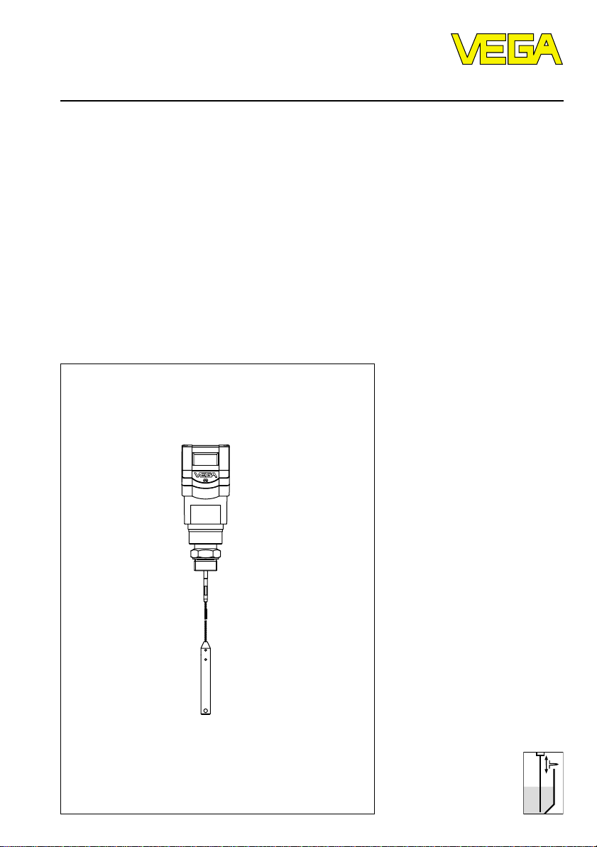
Level and Pressure
Operating Instructions
VEGAFLEX 51K

2 VEGAFLEX 51K
Safety information / Note Ex area
Safety information
Please read this manual carefully, and also take
note of country-specific installation standards
(e.g. the VDE regulations in Germany) as well
as all prevailing safety regulations and acci-
dent prevention rules.
For safety and warranty reasons, any internal
work on the instruments, apart from that in-
volved in normal installation and electrical con-
nection, must be carried out only by qualified
VEGA personnel.
Note Ex area
Please note the approval documents (yellow
binder), and especially the included safety
data sheet.

VEGAFLEX 51K 3
Contents
Safety information ........................................................................ 2
Note Ex area ................................................................................ 2
1 Product description
1.1 Function ................................................................................. 4
1.2 Application features ............................................................. 4
1.3 Types and versions ............................................................. 5
1.4 Type code ............................................................................. 7
1.5 Technical data ....................................................................... 8
1.6 Dimensions ......................................................................... 11
2 Mounting
2.1 Installation instructions ...................................................... 12
3 Electrical connection .............................................................. 15
3.1 Connection and connection cable .................................... 15
3.2 Connection of the sensor .................................................. 17
3.3 Connection of the indicating instrument VEGADIS 50 .... 19
4 Setup
4.1 Adjustment methods .......................................................... 20
4.2 Adjustment with adjustment module MINICOM ............... 20
4.3 Adjustment with the PC ...................................................... 26
4.4 Adjustment with HART
®
handheld ..................................... 29
5 Diagnostics
5.1 Simulation ............................................................................ 30
5.2 Failure rectification ............................................................. 30
Contents

4 VEGAFLEX 51K
Product description
1 Product description
1.1 Function
High frequency microwave impulses are
guided along a steel rope.
The microwave impulses are reflected when
reaching the product surface. The impulse
running time is processed by the integrated
electronics and outputted as level.
The sensors detect levels in all types of sol-
ids. Density, conductivity and dielectric value
of the product do not influence the measure-
ment. Also, varying product properties can-
not influence the measured value.
Lime, cement, cereals, plastic granules, flour,
gravel - VEGAFLEX microwave sensors
solve the most difficult application problems
involving solids. Even in products with vary-
ing moisture or fluctuating dielectric constant,
the level is reliably detected. High, narrow
vessels in which a non-contact measuring
principle often delivers less than optimum
measuring results, can be measured without
problem by VEGAFLEX. VEGAFLEX 51 is
equipped with a cable of 4 mm diameter and
is available up to a length of 10 m.
• Adjustment without filling or emptying of the
vessel.
• 4 … 20 mA two-wire sensors, supply and
measuring signal via one two-wire cable
(loop powered).
• Up to 15 sensors can be connected via
one two-wire cable.
• Measuring range up to 10 m with small min.
distance.
• Unaffected by application conditions such
as:
- dust and noise generation
- moisture changes
- varying products
• Existing cable systems can be still used in
four-wire technology.
• Unaffected by the vessel material, e.g.
metal, concrete, plastic etc.
• As an option, the display with adjustment
can be separated from the sensor.
• Connection to all bus systems: Modbus,
Interbus S, Siemens 3964R, Profibus DP,
Profibus FMS, ASCII.
• Low wiring costs by using bus systems or
two-wire technology.
1.2 Application features
Applications
• Level measurement of solids.
• Measurement also in vacuum.
• All slightly conductive substances and all
substances with a dielectric value e
r
> 1.8
can be measured.
• Measuring range 0 ... 10 m.
Two-wire technology
• Supply, signal transmission and output
signal on one two-wire cable.
• 4 … 20 mA output signal or digital output
signal.
Rugged
• Highly resistant materials: PA, 1.4401.
Precise and reliable
• Resolution 1 mm.
• Unaffected by noise, steam, dusts, gas
compositions and inert gas stratification.
• Unaffected by varying density.
• Measurements under pressure up to
16 bar and with product temperatures up
to 120°C.
Communicative
• Integrated display of measured values.
• As an option, display can be separated
from the sensor.
• Adjustment from the PLC level.
Approvals
• Ex Zone 0
- EExd ia IIC
- EEx ia IIC
• ATEX
• StEx Zone 10
VEGAFLEX 51K 5
Adjustment with HART
®
handheld
Series 50 with 4 … 20 mA output signal can
also be adjusted with the HART
®
handheld or
via a PC with HART
®
software (e.g. Smart
version). A special DDD (Data Device De-
scription) is not necessary, so that the sen-
sors can be adjusted with the HART
®
standard menus of the handheld.
-
+
ESC
OK
Tank 1
m (d)
12.345
Detachable adjustment module MINICOM
Product description
Adjustment with PC
The setup and adjustment of the VEGAFLEX
sensors is generally made on the PC with the
adjustment program VEGA Visual Operating
(VVO) under Windows
®
.
The program leads
quickly through adjustment and parameter
setting by means of pictures, graphics and
process visualisations.
The PC can be connected to any individual
position of the system or the signal cable.
This is done by connecting the two-wire PC
interface converter VEGACONNECT 2 to the
sensor or the signal cable.
The adjustment and parameter setting data
can be saved with the adjustment software
on the PC and can be protected by pass-
words. On request, the adjustments can be
quickly transferred to other sensors.
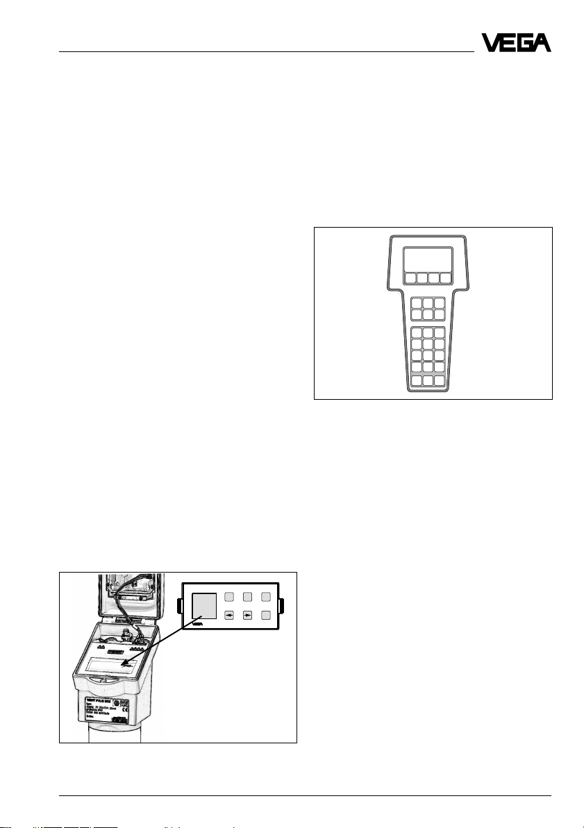
Adjustment with adjustment module
MINICOM
With the small (3.2 cm x 6.7 cm) 6 key adjust-
ment module, the adjustment can be carried
out in clear text dialogue.
The adjustment module can be plugged into
VEGAFLEX or the external indicating instru-
ment VEGADIS 50.
Adjustment of VEGAFLEX from the external
indicating instrument VEGADIS 50 is there-
fore possible.
1.3 Types and versions
VEGAFLEX series 50 K
In general, all VEGAFLEX series 50 K sen-
sors can be adjusted with the pluggable
adjustment module MINICOM or with any
standard HART
®
handheld. With the software
VEGA Visual Operating (VVO), it is also pos-
sible to adjust the sensor with a PC.
4 … 20 mA sensors
Two-wire sensors fro connection to a power
supply unit or a PLC.
Compact sensors with mains supply
The sensors deliver a level-proportional
4 … 20 mA signal, which can be processed
in a PLC.
HART Communicator
HART
®
handheld
6 VEGAFLEX 51K
4
+
2
-
+
-
2
2
2 2
VEGADIS 50
VEGAFLEX
4 … 20 mA
VEGADIS 11
PLC
VEGADIS 371 Ex
Relay (4 x)
0/4 … 20 mA
4 … 20 mA
passive
4 … 20 mA
passive
1
2
3
separate power supply with
four-wire technology
Product description
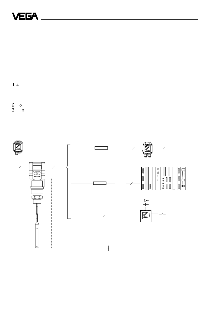
Configuration
A measuring system with a VEGAFLEX can
be realised in different ways (see following
figure).
The external indicating instrument VEGADIS
50 can be separated up to 25 m from the
sensor.
Two-wire technology
1
4 ... 20 mA sensor, supply and measuring
signal via one two-wire cable (loop-pow-
ered), indicating instrument VEGADIS 11
only possible in four-wire technology.
2
Connection to a PLC (active).
3
Connection to an indicating instrument
VEGADIS 371 with up to 4 relay outputs.
Four-wire technology
In addition to a two-wire signal cable, these
measuring systems have a separate supply
cable.
E.g. this is necessary when using a passive
PLC, the inputs of which cannot power the
connected sensors.
This cable is shown in the drawing as a bro-
ken line.
1)
1)
1)
only with HART
®
VEGAFLEX 51K 7
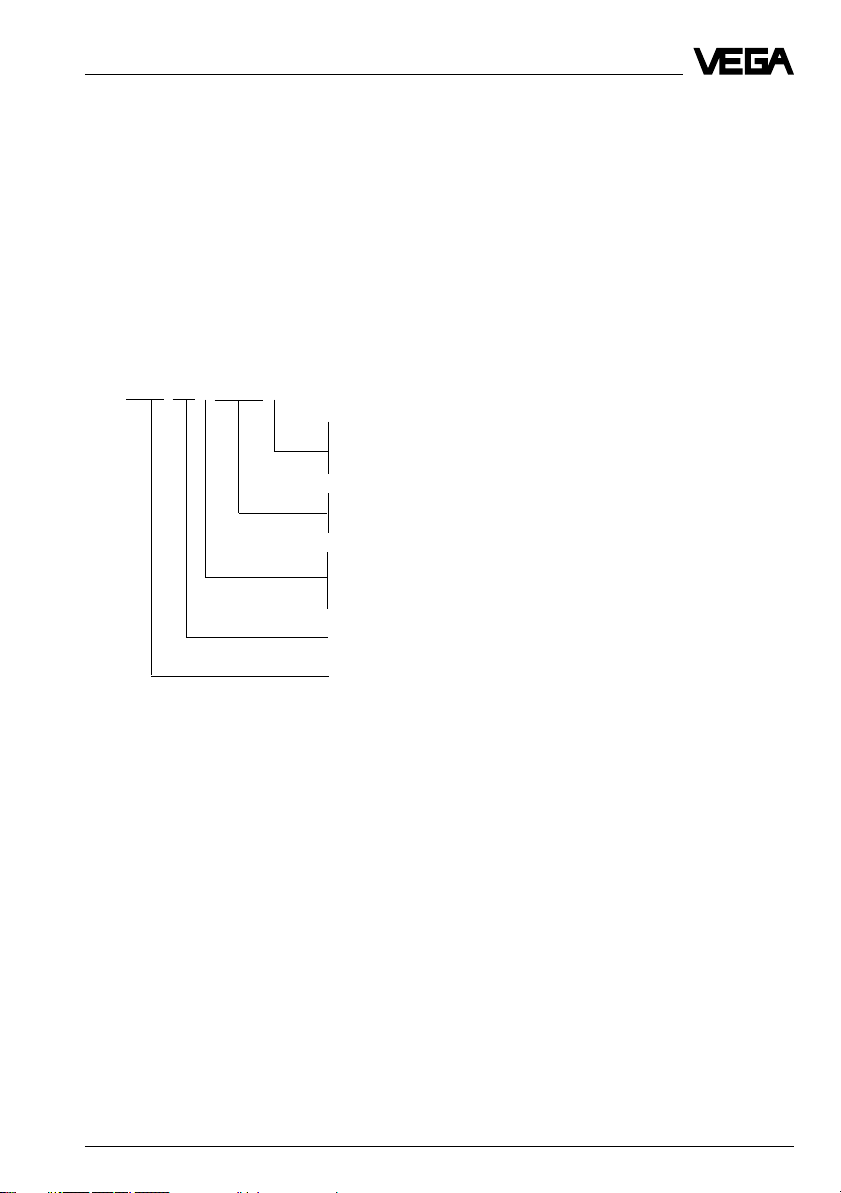
VEGAFLEX 51 K EXS.X X
B - 20…72 V DC, 20…250 V AC / 4 … 20 mA output, HART
®
D - Two-wire loop-powered / 4 … 20 mA output, HART
®
E - Supply via signal conditioning instrument / VBUS output
EXS - StEx Zone 10 approved
EX0 - Ex Zone 0 acc. to PTB and ATEX II 1/2 G
V - Digital output signal (two-wire technology)
K - Analogue 0 … 20 mA output signal (two or
four-wire technology)
Instrument series with 4 mm cable
Measuring technology (FLEX for guided microwave)
1.4 Type code
The second figure of the type name, e.g.
VEGAFLEX 5[1]… distinguishes the instru-
ments according to the stability of the cable.
The letter, e.g. VEGAFLEX 51[K] character-
ises the output signal:
K stands for an analogue 4 … 20 mA output
signal (compact instrument)
V stands for a digital output signal (VBUS).
Product description
8 VEGAFLEX 51K
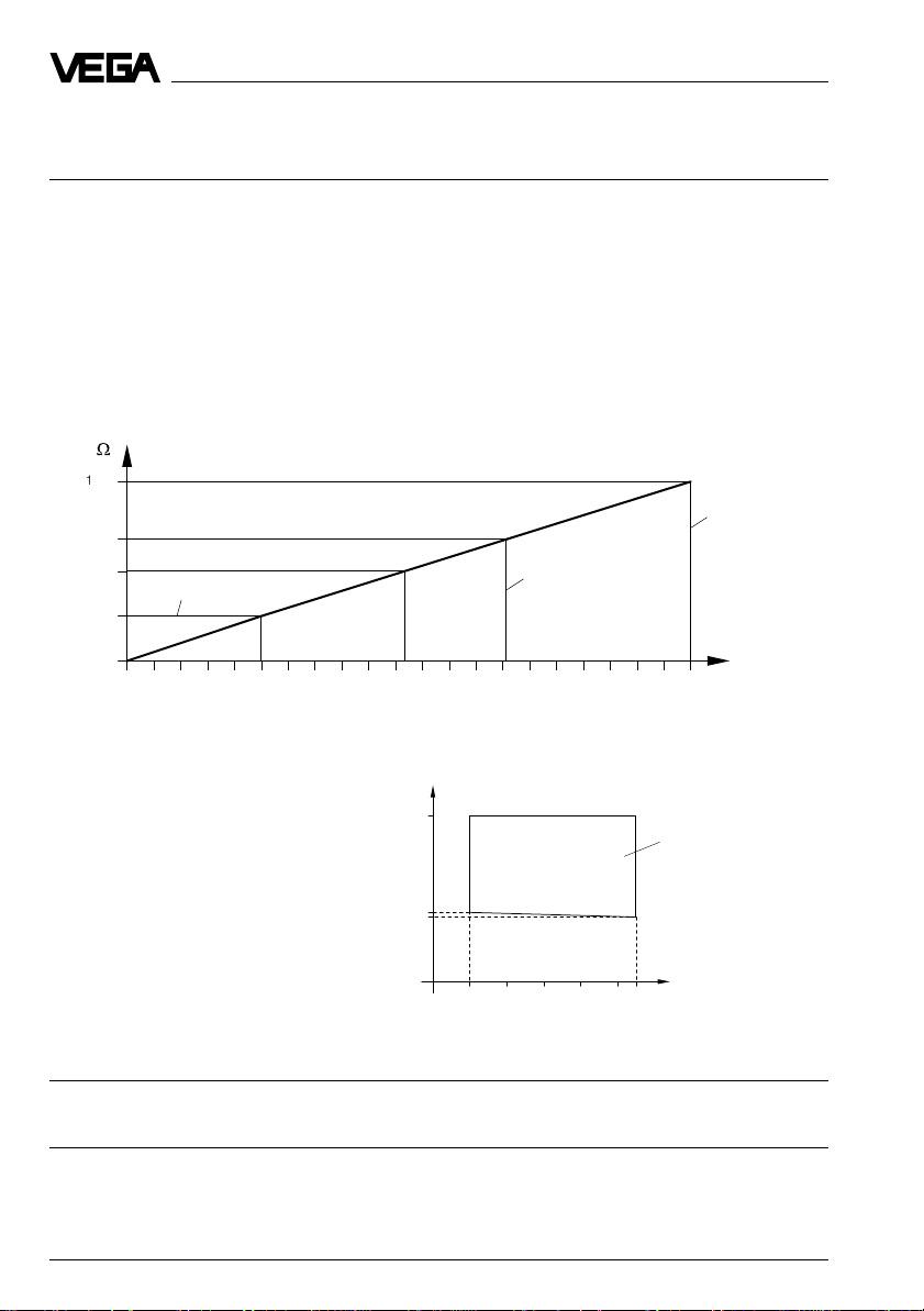
The min. supply voltage depends on the sensor current.
04 22
mA
14
15
36
V
Range of the required
terminal voltage on the
sensor
Sensor current
Product description
1.5 Technical data
Power supply
Supply voltage
- two-wire sensor 24 V DC (15 … 36 V DC)
- four-wire sensor 24 V DC (20 … 72 V)
230 V AC (20 … 250 V), 50/60 Hz
fuse 0.315 A TR
Current consumption
- two-wire sensor max. 22.5 mA
- four-wire sensor max. 60 mA
Power consumption
- two-wire sensor max. 810 mW
- four-wire sensor max. 1.2 W
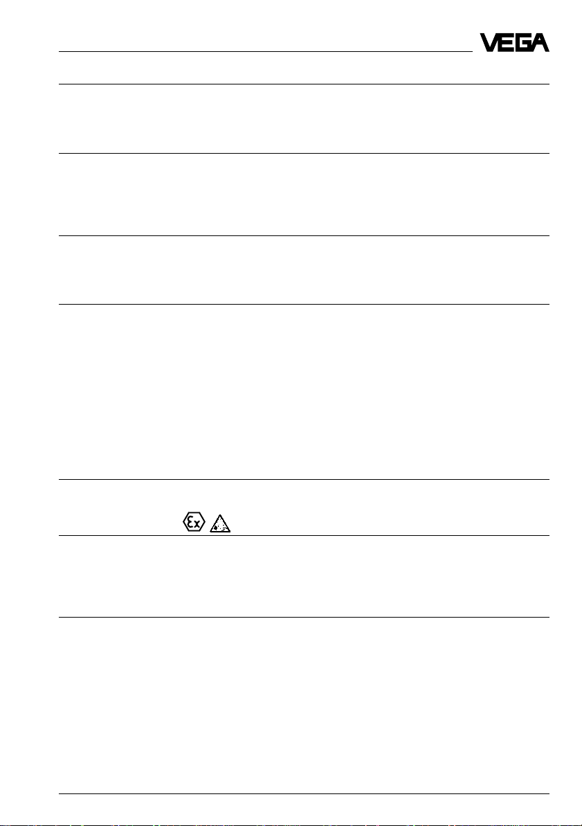
V
W
1000
680
500
250
0
20 22 24 26 28 30 32 34 3615 16 18
Voltage limit
non Ex sensor
Voltage limit
Ex sensor
HART
®
load
Voltage supply
Measuring range
VEGAFLEX 51 0.3 ... 10 m
Output signal
4 … 20 mA current signal, load max. 500 W
VEGAFLEX 51K 9
Product description
Adjustment
- PC and adjustment software VEGA Visual Operating
- adjustment module MINICOM
- HART
®
handheld
Accuracy (under reference conditions acc. to IEC 770 - relating to the max. meas. range)
Linearity error < 0.1 %
Temperature drift 0.015 %/10 K
Resolution of the 4 … 20 mA signal 0.025 % of range (DA converter)
Resolution 1 mm
Characteristics
Min. span between
full and empty adjustment
- analogue output signal 10 mm
Ambient conditions
Vessel pressure -1 … 16 bar
Ambient temperature on the housing -40°C … +60°C
Process temperature -40°C … +120°C
Storage and transport temperature -40°C … +80°C
Protection IP 66/IP 67 (meets both protection standards)
Protection class
- two-wire sensor II
- four-wire sensor I
Overvoltage category III
Max. tensile load cable ø 4 mm: 10 KN (check the max. tensile
load of the silo ceiling)
Process fittings
VEGAFLEX 51 G 1
1
/
2
A, 1
1
/
2
“ NPT
steel chromized or 1.4301 (stainless steel)
Ex technical data
StEx zone 10 (only two-wire sensors)
Ex-Zone 0 acc. to PTB and ATEX II 1/2 G
The permissible operating data of the VEGAFLEX sensors for Ex or StEx areas are listed in
the certificate.
Materials
Housing PBT (Valox) or
aluminium (powder-coated)
Cable 1.4401 (stainless steel; 316) or
galvanized steel - PA-coated
10 VEGAFLEX 51K
Product description
Connection cables
Two-wire sensor
- Supply and signal via one two-wire cable.
The cable resistance depends on the supply voltage (see diagram).
Four-wire sensor
- Supply and signal separate,
cable resistance of the 4 … 20 mA signal cable max. 500 W
Profibus PA sensor
- recommended cable types - SINEC 6XV1 830-5AH10 (Siemens AG)
- SINEC L2 6XV1 830-35H10 (Siemens AG)
- 3079 a (Belden)
- max. cable length 100 m field distributor to sensor
Conductor cross-section generally 2.5 mm
2
Ground connection max. 4 mm
2
Cable entry 2 x M20 x 1.5 (cable diameter 5 … 9 mm)
CE conformity
VEGAFLEX sensors meet the protective regulations of EMC (89/336/EWG) and NSR
(73/23/EWG). Conformity has been judged acc. to the following standards:
EMC Emission EN 50 081 - 1: 1992
Susceptibility EN 50 082 - 2: 1995
NSR EN 61 010 - 1: 1993
Display
Display scalable, analogue and digital display of
measured values (option).
An external display of measured value, powered by the sensor, can be mounted at a dis-
tance of up to 25 m from the sensor.
Signal output
Signal output
- two-wire technology 4 … 20 mA (see diagram)
- four-wire technology 4 … 20 mA
Resolution of the 20 mA signal 0.025 % of range
Load 0 … 500 W
Two-wire technology:
The analogue 4 … 20 mA output signal (measuring signal) is transmitted together with the
power supply via one two-wire cable.
Four-wire technology:
Separate power supply.
The analogue 4 … 20 mA output signal (measuring signal) is transmitted in a cable sepa-
rated from the power supply.
Loading...