


 Loading...
Operating Instructions
VEGAPULS 43
4 … 20 mA; HART® compact sensor

Contents
Contents
|
Safety information ........................................................................ |
3 |
|
|
Note Ex area ................................................................................ |
3 |
|
1 |
Product description .................................................................. |
4 |
|
|
1.1 |
Function ................................................................................. |
4 |
|
1.2 |
Application features ............................................................. |
6 |
|
1.3 |
Adjustment ............................................................................ |
7 |
2 |
Types and versions ................................................................... |
9 |
|
|
2.1 |
Type survey .......................................................................... |
9 |
|
2.2 |
Antenna ............................................................................... |
10 |
3 |
Mounting and installation ..................................................... |
11 |
|
|
3.1 |
General installation instructions ........................................ |
11 |
|
3.2 |
Measurement of liquids ..................................................... |
14 |
|
3.3 |
Measurement in standpipe (surge or bypass tube) ...... |
15 |
|
3.4 |
False echoes ...................................................................... |
21 |
|
3.5 |
Common installation mistakes ........................................... |
22 |
4 |
Electrical connection .............................................................. |
25 |
|
|
4.1 |
Connection and connection cable .................................... |
25 |
|
4.2 |
Connection of the sensor .................................................. |
27 |
|
4.3 |
Connection of the external indicating instrument |
|
|
|
VEGADIS 50 ....................................................................... |
31 |
|
4.4 |
Configuration of measuring systems ............................... |
32 |
5 |
Set-up ........................................................................................ |
40 |
|
|
5.1 |
Adjustment media .............................................................. |
40 |
|
5.2 |
Adjustment with PC ............................................................ |
40 |
|
5.3 |
Adjustment with adjustment module MINICOM ............... |
42 |
|
5.4 |
Adjustment with HART® handheld ................................... |
48 |
6 |
Diagnostics ............................................................................... |
50 |
|
|
6.1 |
Simulation ............................................................................ |
50 |
|
5.2 |
Error codes ........................................................................ |
50 |
|
|
|
|
2 |
|
|
VEGAPULS 43 – 4 … 20 mA |
041227-EN-26626

Contents
7 Technical data .......................................................................... |
51 |
|
7.1 |
Technical data ..................................................................... |
51 |
7.2 |
Approvals ........................................................................... |
56 |
7.3 |
Dimensions ......................................................................... |
57 |
Supplement ..................................................................................... |
|
59 |
|
Safety Manual |
................................................................................. |
59 |
|
1 |
General ............................................................................... |
59 |
|
|
1.1 |
Validity ................................................................................. |
59 |
|
1.2 |
Area of application ............................................................... |
59 |
|
1.3 |
Relevant standards ............................................................. |
59 |
|
1.4 |
Determination of safety-related characteristics .................. |
60 |
2 |
Planning .............................................................................. |
61 |
|
|
2.1 |
Low demand mode ............................................................... |
61 |
|
2.2 |
High demand or continuous mode ....................................... |
61 |
|
2.3 |
General ................................................................................ |
61 |
3 |
Set-up |
................................................................................. |
62 |
|
3.1 |
Mounting and installation ..................................................... |
62 |
|
3.2 |
Adjustment instructions and parameter adjustment ........... |
62 |
|
3.3 |
Configuration of the processing unit ................................... |
62 |
4 |
Reaction during operation and in case of failure ............. |
63 |
|
5 |
Recurring function test ....................................................... |
63 |
|
6 |
Safety-related characteristics ........................................... |
64 |
|
SIL declaration of conformity .................................................... |
65 |
||
CE conformity declaration ......................................................... |
66 |
||
26626-EN-041227
Safety information
Please read this manual carefully, and also take note of country-specific installation standards (e.g. the VDE regulations in Germany) as well as all prevailing safety regulations and accident prevention rules.
For safety and warranty reasons, any internal work on the instruments, apart from that involved in normal installation and electrical connection, must be carried out only by qualified VEGA personnel.
 Note Ex area
Please note the attached safety instructions containing important information on installation and operation in Ex areas.
These safety instructions are part of the operating instructions manual and come with the Ex approved instruments.
VEGAPULS 43 – 4 … 20 mA |
3 |

Product description
1 Product description
Sensors used in the food and pharmaceutical industries must meet very high demands: they must have long-term stability, they must be accurate, robust, easy to set up, chemically resistant and flawlessly hygienic. Many level sensors meet those demands only halfway. Radar sensors, which are otherwise widely used, are not usually found in hygienic and sterile applications because their antennas are difficult to clean. The newly developed VEGAPULS 43 radar sensor was designed especially for areas of application in hygienic and sterile production. Radar sensors are ideal because they operate without touching the medium, are free of wear and ageing, and perform well regardless of pressure (-1 … +40 bar) or temperature
(-40°C … +150°C). The new antenna design of VEGAPULS 43, having no recesses or gaps, presents a smooth surface (like a smooth vessel wall) to CIP and SIP processes. It allows all the methods of modern, environment-friendly system hygiene and has, of course EHEDG, FDA and 3A approvals. The sensor faces the medium only with a small, extremely dense TFM-PTFE surface through which it transmits very small
(0.15 mW) radar pulses. A very fast, intelligent electronics creates from the resulting echoes a precise image of the surroundings and calculates from the pulse running time the level in the vessel every 0.1 s. This value is then outputted as a 4 … 20 mA signal. Compared with the PTFE commonly used in hygienic applications, the improved TFMPTFE has a far denser polymer structure and a noticeably higher surface quality (Ra < 0.8). As a result, proven radar technology is now available for sterile production processes. The spectrum of applications for the new radar sensor is broad and varied: serum production, face cream, fruit juice, etc.
Due to their small housing dimensions and process fittings, the compact sensors are unobstrusive and, above all, cost-effective monitors of your product levels. With their integrated display, they enable highprecision level measurements and can be used for applications in which the advantages of non-contact measurement could never before be realized.
VEGAPULS radar sensors are perfectly adapted to two-wire technology. The supply voltage and the output signal are transmitted via one two-wire cable. The instruments produce an analogue 4 … 20 mA signal as output, i.e. measurement signal.
1.1 Function
Radio detecting and ranging: Radar. VEGAPULS radar sensors are used for noncontact, continuous distance measurement. The measured distance corresponds to a filling height and is outputted as level.
Measuring principle:
emission – reflection – reception
Extremely small 26 GHz radar signals are emitted from the antenna of the radar sensor as short pulses. The radar pulses reflected by the sensor environment and the product are received by the antenna as radar echoes. The running period of the radar pulses from emission to reception is proportional to the distance and hence to the level.
041227-EN-26626
4 |
VEGAPULS 43 – 4 … 20 mA |

26626-EN-041227
Product description |
|
|
|
|
Hence, it is possible for the radar sensors to |
||
|
process the slow-motion pictures of the sen- |
||
|
sor environment precisely and in detail in |
||
|
cycles of 0.5 to 1 second without using time- |
||
|
consuming frequency analysis (e.g. FMCW, |
||
Meas. |
required by other radar techniques). |
||
|
|
||
distance |
|
|
|
|
Nearly all products can be measured |
||
|
Radar signals display physical properties |
||
|
similar to those of visible light. According to |
||
|
the quantum theory, they propagate through |
||
|
empty space. Hence, they are not depend- |
||
|
ent on a conductive medium (air), and they |
||
emission - reflection - reception |
spread out like light at the speed of light. |
||
Radar signals react to two basic electrical |
|||
|
|||
The radar pulses are emitted by the antenna |
properties: |
||
- |
the electrical conductivity of a substance |
||
system as pulse packages with a pulse |
|||
- |
the dielectric constant of a substance. |
||
duration of 1 ns and pulse intervals of |
|||
|
|
||
278 ns; this corresponds to a pulse package |
All products which are electrically conductive |
||
frequency of 3.6 MHz. In the pulse intervals, |
|||
reflect radar signals very well. Even slightly |
|||
the antenna system operates as a receiver. |
|||
conductive products provide a sufficiently |
|||
Signal running periods of less than one bil- |
|||
strong reflection for a reliable measurement. |
|||
lionth of a second must be processed and |
|||
|
|
||
the echo image evaluated in a fraction of a |
All products with a dielectric constant εr |
||
second. |
|||
|
greater than 2.0 reflect radar pulses suffi- |
||
|
ciently (note: air has a dielectric constant εr of |
||
1 ns |
1). Signal reflectivity grows stronger with |
||
increasing conductivity or increasing dielec- |
|||
|
|||
|
tric constant of the product. Hence, nearly all |
||
278 ns |
substances can be measured. |
||
|
|
||
Pulse sequence |
|
|
|
|
% |
|
|
|
|
|
|
|
|
|
|
|
|
||||||
|
|
|
|
50 |
|
|
|
|
|
|
|
|
|
|
40 % |
|
|||||||
VEGAPULS radar sensors can achieve this |
|
|
|
|
|
|
|
|
|
|
|
||||||||||||
40 |
|
|
|
|
|
|
|
|
|
|
|
||||||||||||
|
|
|
|
|
|
|
|
|
|
|
|
||||||||||||
|
|
|
|
|
|
|
|
|
|
|
|
|
|
||||||||||
through a special time transformation proce- |
30 |
|
|
|
|
|
25 % |
|
|
|
|
|
|
||||||||||
|
|
|
|
|
|
|
|
|
|
|
|||||||||||||
dure which spreads out the more than 3.6 |
20 |
|
|
|
|
|
|
|
|
|
|
|
|
||||||||||
million echo images per second into a quasi |
10 |
|
5 % |
|
|
|
|
|
|
|
|
|
|
||||||||||
slow-motion picture, then freezes and proc- |
5 |
|
|
|
|
|
|
|
|
|
|
|
|
||||||||||
|
|
|
|
|
|
|
|
|
|
0 |
|
|
|
|
|
|
|
|
|
|
|
|
|
esses them. |
|
|
|
|
|
|
0 |
|
|
|
10 |
|
|
|
|
20 εr |
|||||||
|
|
|
|
|
|
|
|
|
|
|
|
2 |
4 |
6 |
8 |
|
12 |
14 |
16 |
18 |
|
|
|
|
|
|
|
|
|
|
|
|
|
|
|
|
|
|
|
|
|
|
|
|
|
|
|
|
|
|
|
|
|
|
|
|
|
Reflected radar power dependent on the dielectric |
|||||||||||||
|
|
|
|
|
|
|
|
|
|
||||||||||||||
|
|
|
|
|
|
|
|
|
|
constant of the measured product |
|
|
|
|
|||||||||
|
|
|
|
|
|
|
|
|
|
|
|
|
|
|
|
|
|
|
|
|
|
|
|
|
|
|
|
|
|
|
|
|
|
|
|
|
|
|
|
|
|
|
|
|
|
|
|
|
|
|
|
|
|
|
|
|
|
|
|
|
|
|
|
|
|
|
|
|
|
|
|
|
|
|
|
|
|
|
|
|
|
|
|
|
|
|
|
|
|
|
|
|
|
|
|
|
|
|
t |
|
|
t |
|
|
|
|
|
|
|
|
|
|
|
|
|
|
|||
|
|
|
|
|
|
|
|
|
|
|
|
|
|
|
|
|
|
|
|
|
|
|
|
|
|
|
|
|
|
|
|
|
|
|
|
|
|
|
|
|
|
|
|||||
Time transformation |
|
|
|
|
|
|
|
|
|
|
|
|
|
|
|
|
|
|
|||||
|
|
|
|
|
|
|
|
|
|
|
|
|
|
|
|
|
|
|
|
|
|
|
|
VEGAPULS 43 – 4 … 20 mA |
|
|
|
|
|
|
|
|
|
|
|
|
|
|
|
|
5 |
||||||

|
|
|
Product description |
|
With standard flanges of DN 50 to DN 150, |
1.2 Application features |
|||
ANSI 2“ to ANSI 6“ or G 1½ A and 1½“ NPT, |
|
|
||
the sensor antenna systems can be adapted |
Applications |
|||
to various products and measuring environ- |
||||
• |
level measurement of any liquid |
|||
ments. |
||||
• measurement also in vacuum |
||||
|
|
|||
The high-quality materials can also withstand |
• |
all slightly conductive materials and all |
||
|
substances with a dielectric constant > 2.0 |
|||
extreme chemical and physical conditions. |
|
|||
• measuring range 0 … 10 m (DN 50). |
||||
The sensors deliver stable, reproducible |
||||
|
measuring range 0 … 20 m (DN 80, DN |
|||
analogue or digital level signals with reliability |
|
|||
|
100, DN 150). |
|||
and precision. |
|
|||
|
|
|||
|
|
Two-wire technology |
||
Continuous and reliable |
• power supply and output signal on one |
|||
|
two-wire cable (Loop powered) |
|||
Unaffected by temperature, pressure and |
• 4 … 20 mA output signal or HART® output |
|||
|
signal. |
|||
atmosphere content, VEGAPULS radar sen- |
|
|
||
sors are used for quick and reliable continu- |
Rugged and abrasionproof |
|||
ous level measurement of widely varying |
• |
non-contact |
||
products. |
• |
high-resistance materials |
||
% |
|
|
|
|
Exact and reliable |
0,03 |
|
|
0,023 % |
|
• accuracy 0.05 %. |
0,02 |
|
|
|
• resolution 1 mm |
|
|
0,018 % |
|
|
||
0,01 |
|
|
|
|
• unaffected by noise, vapours, dusts, gas |
0 |
|
|
|
|
compositions and inert gas stratification |
0 |
100 |
500 |
1000 |
1300 ˚C |
• unaffected by varying density and tem- |
|
|
|
|
|
|
Temperature influence: Temperature error absolutely |
perature of the medium |
||||
zero (e.g. at 500°C 0.018 %) |
|
|
• measurement in pressures up to 16 bar |
||
|
|
|
|
|
and product temperatures up to 150°C. |
% |
|
|
|
|
|
|
|
|
|
|
|
|
|
|
10 |
|
|
|
|
|
|
|
|
|
|
|
|
|
|
5 |
|
|
|
|
|
|
|
|
|
2,8 % |
|
|
|
3,89 % |
|
|
|
|
|
1,44 % |
|
|
|
|
|
|
|
||
|
0,29 % |
|
|
|
|
|
|
|
|
|
|
|||
0 |
|
|
|
|
|
|
|
|
|
|
|
|
||
10 |
20 |
30 |
40 |
|
60 |
70 |
80 |
90 |
|
110 |
120 |
130 |
140 bar |
|
0 |
50 |
100 |
||||||||||||
Pressure influence: Error with pressure increase very low (e.g. at 50 bar 1.44 %)
Communicative
•integrated measured value display
•optional display module separate from sensor
•adjustment with detachable adjustment module, pluggable in the sensor or in the external display
•adjustment with HART® handheld
•adjustment with the PC.
Approvals
• CENELEC, ATEX, PTB, FM, CSA, ABS, LRS, GL, LR, FCC.
041227-EN-26626
6 |
VEGAPULS 43 – 4 … 20 mA |

Product description
1.3 Adjustment |
The PC can be connected at any measuring |
|
|
site in the system or directly to the signal |
|
Every measurement set-up is unique. For |
cable. It is connected by means of the two- |
|
wire PC interface converter VEGACONNECT 3 |
||
that reason, every radar sensor needs some |
||
to the sensor or the signal cable. The adjust- |
||
basic information on the application and the |
||
ment and parameter data can be saved with |
||
environment, e.g. which level means "empty“ |
||
the adjustment software on the PC and can |
||
and which level "full“. Beside this "empty and |
||
be protected by passwords. On request, the |
||
full adjustment“, many other settings and |
||
adjustments can be quickly transferred to |
||
adjustments are possible with VEGAPULS |
||
other sensors. |
||
radar sensors. |
||
|
The adjustment and parameter setting of radar sensors is carried out with
-the PC
-the detachable adjustment module MINICOM
-the HART® handheld
Adjustment with the PC
The set-up and adjustment of the radar sensors is generally done on the PC with the adjustment software PACTwareTM. The program leads quickly through the adjustment and parameter setting by means of pictures, graphics and process visualisations.
2 |
2 PLC
Adjustment with the PC on the 4 … 20 mA signal and supply cable or directly on the sensor (figure: a twowire sensor)
2
4 ...20 mA
2
Adjustment with the PC on the analogue 4 … 20 mA signal and supply cable or directly on the sensor (four-wire sensor)
26626-EN-041227
VEGAPULS 43 – 4 … 20 mA |
7 |

Product description
Adjustment with the adjustment module MINICOM
The small (3.2 cm x 6.7 cm) 6-key adjustment module with display allows the adjustment to be carried out in clear text dialogue. The adjustment module can be plugged into the radar sensor or into the optional, external indicating instrument.
Adjustment with the HART® handheld
Series 40 sensors with 4 … 20 mA output signal can also be adjusted with the HART® handheld. A special DDD (Data Device Description) is not necessary - the sensors can be adjusted with the HART® standard menus of the handheld.
Tank 1 - + ESC
m (d)
12.345 
 OK
OK
Detachable adjustment module MINICOM
Unauthorised sensor adjustments can be prevented by removing the adjustment module.
HART Communicator 

HART® handheld
To make adjustments, simply connect the HART® handheld to the 4 … 20 mA output signal cable or insert the two communication cables of the HART® handheld into the adjustment jacks on the sensor.
Tank 1 |
- |
+ |
ESC |
|
|||
m (d) |
|
|
|
12.345 |
|
|
OK |
|
|
|
2 |
4 ...20 mA |
2 |
|
|
|
|
|
4 ... 20 mA |
2 |
|
|
|
|
|
||
Tank 1 |
- + |
ESC |
|
|
|
|
|
||
m (d) |
|
|
|
|
12.345 |
|
OK |
|
|
4
HART® handheld on the 4 … 20 mA signal cable
Adjustment with detachable adjustment module. The adjustment module can be plugged into the radar sensor or into the external indicating instrument VEGADIS 50.
041227-EN-26626
8 |
VEGAPULS 43 – 4 … 20 mA |

Types and versions
2 Types and versions
2.1 Type survey
VEGAPULS 43 sensors are manufactured with three process connections:
-flange connections (block flanges) in DN 50, 80, 100, 150, ANSI 2“, 3“, 4“, 6“
-TRI-Clamp 2“
-hygienic fitting DN 50.
Survey of features
General features
•Application preferably for liquids in storage tanks and process vessels with increased accuracy requirements.
•Measuring range 0 … 10 m or 0 … 20 m.
•Ex approved in Zone 1 (IEC) or Zone 1 (ATEX) classification mark EEx ia [ia] IIC T6.
•Integrated measured value display.
Survey
26626-EN-041227
Signal outputs
-active (4 … 20 mA)
-passive (4 … 20 mA, loop powered)
Process fitting, optionally available with
-DN 50; ANSI 2“
-DN 80; ANSI 3“
-DN 100; ANSI 4“
-DN 150; ANSI 6“
-TRI-Clamp (50, 80)
-hygienic fitting (50, 80)
Adjustment
-PC
-adjustment module in the sensor
-adjustment module with external indicating instrument
-HART® handheld
Measuring range |
|
|
- |
DN 50, ANSI 2“ |
0 … 10 m |
- |
DN 80, ANSI 3“ |
0 … 20 m |
- |
DN 100, ANSI 4“ |
0 … 20 m |
- |
DN 150, ANSI 6“ |
0 … 20 m |
- |
TRI-Clamp 50, 80 |
0 … 10 m |
- hygienic fitting 50, 80 |
0 … 10 m |
|
|
|
|
|
|
|
VEGAPULS 43 – 4 … 20 mA |
9 |
|

Types and versions
2.2 Antenna |
Hygienic design |
The antenna is the eye of the radar sensor. The shape of the antenna, however, doesn’t give a casual observer the slightest clue on how carefully the antenna geometry must be adapted to the physical properties of electromagnetic waves. The hygienic VEGAPULS 43 radar sensors are equipped with an antenna that can be cleaned as easily as a smooth vessel wall. The previously used horn and rod antennas are gone. Only a small coneshaped bulge protrudes into the process vessel. The small cone acts like a lens that focuses the radar signals into a high-fre- quency beam. The relative dielectric constant of the small 140° PTFE cone represents the calculation index of the lens. The visible part of the antenna (small cone), however, does not give a clue as to how precisely the geometrical form of the antenna has to be adapted to the physical properties of electromagnetic waves. The shape governs the focusing of the waves and hence the sensitivity, just as shape governs the sensitivity of a unidirectional microphone. The production of such an electromagnetic lens requires much empirical knowledge in the areas of high-frequency physics and materials science.
Beside the aforementioned geometry necessary for antennas used in the food and pharmaceutical industry, the choice of materials for the newly developed VEGAPULS 43 sensors is critical for cleaning and sterilisation. Fully automatic cleaning (CIP) and sterilisation (SIP) of entire production facilities (without disrupting production or having to dismantle and disassemble parts of the equipment) is, in practice, not an easy task. Dirt and contaminants get trapped mechanically in pores, fissures, scratches and recesses, and even remain on smooth walls due to electrostatic attraction.
PTFE is commonly found in hygienic applications. The small plastic cone of the sterile, pharmaceutical VEGAPULS 43 radar sensor, which is at the same time antenna and process seal, consists of a TFM-PTFE material. This is a fluorothermoplastic which has additional distinct advantages compared to PTFE, such as e.g., reduced load deformation, denser polymer structure as well as smoother surface (Ra < 0.8 µm). The other known advantages of PTFE, such as, e.g., higher temperature resistance (< 200°C), high chemical resistance as well as resistance to brittleness and ageing are still present or have even been enhanced. Perfluorelastomers and fluorthermoplasts are resistant to virtually all chemical media, such as e.g., amines, ketones, esters, acids (sulphuric acid, phosphoric acid, hydrochloric acid, nitric acid), alkalis (caustic soda), oxidants, fuels and oils. Beside their use in the chemical industry, these materials are being applied more and more in sterilisation and pharmaceutical technologies. The only limits to these materials are in applications with fluorine under high pressure or with liquid alkali metals (sodium or potassium), where explosive reactions may occur.
041227-EN-26626
10 |
VEGAPULS 43 – 4 … 20 mA |
Mounting and installation
3 Mounting and installation
3.1 General installation instructions
Measuring range
The reference plane for the measuring range of the sensor is the lower edge of the flange.
Keep in mind that in measuring environments where the medium can reach the sensor flange, buildup may form on the antenna and later cause measurement errors.
Note: The series 40 sensors are suitable for measurement of solids only under certain conditions.
empty full |
Reference plane |
|
max. |
|
max. |
|
Meas.range |
|
min. |
Measuring range (operating range) and max. measuring distance Note: Use of the sensors for applications with solids is limited.
False echoes
Flat obstructions and struts cause strong false echoes. They reflect the radar signal with high energy density.
Interfering surfaces with rounded profiles scatter the radar signals into the surrounding space more diffusely and thus generate false echoes with a lower energy density. Hence, those reflections are less critical than those from a flat surface.
If flat obstructions in the range of the radar signals cannot be avoided, we recommend diverting the interfering signals with a deflector. The deflector prevents the interfering signals from being directly received by the radar sensor. The signals are then so lowenergy and diffuse that they can be filtered out by the sensor.
Round profiles diffuse radar signals
Profiles with smooth interfering surfaces cause large false signals
Cover smooth, flat surfaces with deflectors
26626-EN-041227
VEGAPULS 43 – 4 … 20 mA |
11 |
|
|
|
Mounting and installation |
Emission cone and false echoes |
If possible, provide a "clear view“ to the |
||
|
|
product inside the emission cone and avoid |
|
The radar signals are focused by the an- |
vessel installations in the first third of the |
||
tenna system. The signals leave the antenna |
emission cone. |
||
in a conical path similar to the beam pattern |
Optimum measuring conditions exist when |
||
of a spotlight. This emission cone depends |
|||
on the antenna used. Any object in this beam |
the emission cone reaches the measured |
||
cone will reflect the radar signals. Within the |
product perpendicularly and when the emis- |
||
first few meters of the beam cone, tubes, |
sion cone is free from obstructions. |
||
struts or other installations can interfere with |
|
|
|
the measurement. At a distance of 6 m, the |
Examples of vessel echoes |
||
false echo of a strut has an amplitude nine |
|||
times greater than at a distance of 18 m. |
|
|
|
|
|
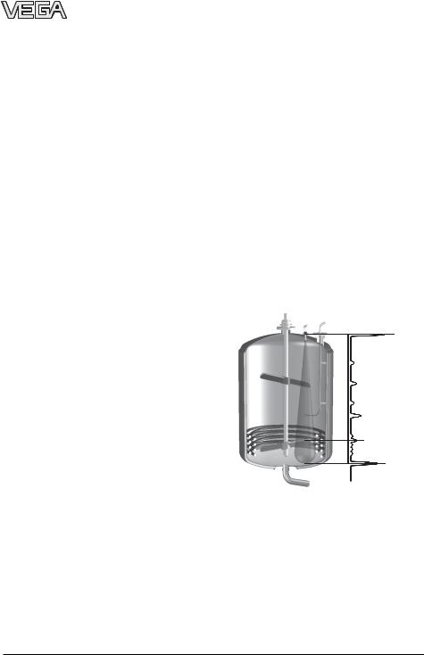
The following vessel images show a typical |
|
At greater distances, the energy of the radar |
echo pattern in a vessel. The example shows |
||
signal distributes itself over a larger area, |
a process vessel with a slow double-bladed |
||
thus causing weaker echoes from obstruct- |
stirrer. In the lower area, the vessel is |
||
ing surfaces. The interfering signals are |
equipped with heating spirals. A thin, angled |
||
therefore less critical than those at close |
inlet tube ends in the vessel centre between |
||
range. |
the stirrer blades. |
||
If possible, orient the sensor axis perpen- |
|
|
|
dicularly to the product surface and keep |
Empty vessel |
||
vessel installations (e.g. pipes and struts) out |
|
|
|
of the emission cone. |
|
|
|
The illustrations of the emission cones are |
|
|
|
simplified and represent only the main beam |
|
|
|
- a number of weaker beams also exist. Un- |
|
|
|
der difficult measuring conditions, the an- |
|
|
|
tenna location and alignment must be chosen |
|
|
|
with the objective of reducing false echoes. |
|
|
|
Only giving attention to the size of the useful |
|
|
|
echo is not adequate when measuring condi- |
|
|
|
tions are unfavourable. |
|
|
|
In a difficult measuring environment, search- |
|
|
|
ing for a mounting location with the lowest |
|
|
|
possible false echo intensity will bring the |
|
|
|
best results. In most cases, the useful echo |
|
|
|
will then be present with sufficient strength. |
|
|
|
With the adjustment software PACTwareTM on |
|
When the vessel is empty, you see the ech- |
|
the PC, you can have a look at the echo im- |
|
oes of the vessel installations around the |
|
age and optimise the mounting location. |
|
emission cone. Beside the large bottom echo, |
|
|
|
|
you see a number of additional false echoes. |
|
|
|
The false echoes of the vessel installations |
|
|
|
are saved during a false echo recording. For |
|
|
|
this reason, the false echo recording must be |
|
|
|
carried out when the vessel is empty. |
041227-EN-26626
12 |
VEGAPULS 43 – 4 … 20 mA |

Mounting and installation
False echoes from the top down: |
The product echo moves to the centre of the |
|
- |
first inlet tube fastening |
meas. range. At the end of the meas. range, |
- |
upper stirrer blade |
you now see an echo at a position where the |
- |
second inlet tube fastening |
bottom echo previously was in the empty |
- |
angled inlet tube |
vessel. This echo is a multiple echo of the |
- |
upper heating tubes |
product echo and is located at twice the |
- |
lower stirrer blade |
distance of the product echo. |
-remaining heating tubes
-vessel bottom
Filled vessel
¼ filling
After filling, the bottom echo is replaced by the product echo.
½ filling
When the vessel is completely filled, you see additional multiple echoes at two, three or four times the distance of the product surface echo.
26626-EN-041227
VEGAPULS 43 – 4 … 20 mA |
13 |

|
|
Mounting and installation |
|
3.2 Measurement of liquids |
The flange screws of VEGAPULS 43 must |
||
|
|
always be tightened with a torque of approx. |
|
Flange antenna |
60 Nm so that the PTFE seal is tight. |
||
Horn antenna on DIN socket piece |
Dished tank tops can act as paraboloidal |
||
reflectors. If the radar sensor is placed in the |
|||
Radar sensors are usually mounted on short |
|||
focal point of the parabolic tank top, the radar |
|||
DIN socket pieces. The lower side of the |
|||
sensor receives amplified false echoes. The |
|||
instrument flange is the reference plane for |
|||
radar sensor should be mounted outside the |
|||
the measuring range. The socket piece |
|||
focal point. Parabolically amplified echoes are |
|||
should be as short as possible. |
|||
thereby avoided. |
|||
|
|
||
max. |
d |
h max. |
50 mm/2" |
100 mm |
|
h |
80 mm/3" |
150 mm |
|
||
|
100 mm/4" |
250 mm |
|
150 mm/6" |
400 mm |
|
d |
|
Deviating socket dimensions
Horn antenna directly on the vessel top
If the stability of the vessel will allow it (sensor weight), flat mounting directly on the vessel top is a good and cost-effective solution. The top side of the vessel is the reference plane.
Mounting on a block flange is especially advantageous. Due to its very shallow recess, it is an ideal solution also for hygienic and aseptic applications.
> 400 mm
Mounting on dished tank end
In vessels with dished or rounded tops, please do not mount the instrument in the centre or close to the vessel wall.
14
041227-EN-26626
VEGAPULS 43 – 4 … 20 mA

26626-EN-041227
Mounting and installation
3.3 Measurement in standpipe |
Make sure the required upper vent hole in |
|
(surge or bypass tube) |
the surge pipe is aligned with the sensor |
|
|
type label. |
|
General instructions |
As an alternative to a surge pipe in the ves- |
|
|
||
Measurement in a standpipe is preferred in |
sel, a pipe antenna system outside the ves- |
|
sel in a bypass tube is also possible. |
||
vessels which contain many installations, e.g. |
||
The surge and bypass tubes must generally |
||
heating tubes, heat exchangers or fast-run- |
||
be made of metal. For plastic tubes, a |
||
ning stirrers. Measurement is then possible |
||
closed, conductive jacket is always required. |
||
when the product surface is very turbulent, |
||
When using a metal tube with plastic inner |
||
and vessel installations can cause no false |
||
coating, make sure that the thickness of the |
||
echoes. |
||
coating is minimal (approx. 2 … 4 mm). |
||
|
||
Due to the concentration of the radar signals |
Align the sensor so that the type label lies on |
|
within the measuring tube, even products |
||
the same axis as the tube holes or the tube |
||
with small dielectric constants (εr= 1.6 up to |
||
connection openings. The polarisation of the |
||
3) can be reliably measured in surge or by- |
radar signals enables a considerably stabler |
|
pass tubes. |
||
measurement with this alignment. |
||
|
Surge pipe welded |
Surge pipe in the |
to the tank |
socket piece |
Type label |
|
max |
max |
Vent hole |
|
ø 5 … 10 mm |
|
min |
min |
|
|
without deflector |
with deflector |
Pipe antenna system in the tank
Type label
> 300 mm
100 %
0 %
Tube flange system as bypass tube
When mounting a VEGAPULS 43 on a bypass tube (e.g. on a previous floating or displacer unit), the radar sensor should be placed approx. 300 mm or more from the max. level.
Surge pipes which are open at the bottom must extend over the full measuring range (i.e. down to 0% level), as measurement is only possible within the tube. The tube inner diameter should be max. 100 mm or correspond to the size of the antenna horn.
VEGAPULS 43 – 4 … 20 mA |
15 |

|
|
Mounting and installation |
|
For products with small dielectric constants |
Connections to the bypass tube |
||
(< 4), the bypass tube should have a length |
|
|
|
greater than would normally be required for |
The connections to the bypass tubes must |
||
the lower tube connection. Products with |
|||
be fashioned in such a way that only minimal |
|||
small dielectric constants are partly pen- |
|||
reflections are caused by the walls of the |
|||
etrated by the radar signals, allowing the |
|||
connecting tubes. This is especially important |
|||
tube bottom to produce a stronger echo than |
|||
for the breather connection in the upper part |
|||
the product (when the bypass tube is nearly |
|||
of the tube. Observe the following points: |
|||
empty). By extending the tube downward, |
|||
• |
Use small openings for the connection. |
||
some liquid remains at the bottom even when |
|||
• |
The diameter of the connecting tubes |
||
the vessel is completely empty. |
|||
|
should not exceed 1/3 of the bypass diam- |
||
|
|
||
|
|
eter. |
|
|
• |
The tube connections must not protrude |
|
Type label |
|
into the bypass tube. |
|
|
• Large welding beads in the tubes should |
||
|
|
be avoided. |
|
> 300 mm |
• |
Additional connections to the bypass tube |
|
|
must lie in the same plane as the upper |
||
|
|
||
100 % |
|
and lower vessel connection (above each |
|
|
|
other or displaced by 180°). |
|
0 % |
|
|
|
300 ... 800 mm |
|
|
|
Tube flange system as bypass tube |
|
|
|
If enough liquid (300 … 800 mm) remains in |
|
|
|
the blind lower end of the tube, the portion of |
|
|
|
the signal that penetrates the liquid and re- |
Optimum connection to the bypass tube |
||
flects from the tube bottom is sufficiently |
|
|
|
damped - the sensor can then easily distin- |
|
|
|
guish it from the echo of the liquid surface. In |
|
|
|
cases where there is not enough liquid at the |
|
|
|
bottom of the tube, a deflector situated there |
|
|
|
will carry out the same function. It deflects |
|
|
|
signals that reach the tube bottom into the |
|
|
|
standard connection opening. |
|
|
|
|
Welding beads too large |
||
041227-EN-26626
16 |
VEGAPULS 43 – 4 … 20 mA |

Mounting and installation
Tube connection protrudes
Additional connection in the bypass tube in one plane
Use of guide tubes
In case of very rough inner surfaces in existing bypass tubes (e.g. due to corrosion), large connecting tube openings, as well as bypass tubes with more than 100 mm inner diameter, the use of a guide tube inside the existing bypass tube is recommended. This reduces the noise level and increases measurement reliability considerably. The flange of the guide tube can be easily mounted as a sandwich flange between vessel and sensor flange.
Guide tube
Guide tube in existing surge or bypass tubes
To increase the min. distance, the guide tube can project out of the surge or bypass tube. This can be done by welding a flat welding flange on the outside of the extended guide tube. In both cases, an appropriate breather hole is necessary.
Extended guide tube
26626-EN-041227
VEGAPULS 43 – 4 … 20 mA |
17 |

Seals on tube connections and tube extensions
Microwaves are very sensitive to gaps in flange connections. If connections are made without proper care, distinct false echoes as well as increased signal noise can result. Observe the following points:
•The applied seal should correspond to the tube inner diameter.
•If possible, conductive seals such as conductive PTFE or graphite should be used.
•There should be as few seal positions as possible in the guide tube.
Flange connections on bypass tubes
Adhesive products
With non-adhesive or slightly adhesive products, use a surge pipe with a nominal width of e.g. 50 mm. VEGAPULS 43 radar sensors with 26 GHz technology are for the most part insensitive to buildup in the measuring tube. Nevertheless, buildup should not block the measuring tube.
For products with somewhat heavier buildup, the use of a DN 80 to max. DN 100 standpipe or surge pipe can make measurement possible despite buildup. But with extremely adhesive products, measurement in a standpipe is not possible at all.
18
Mounting and installation
Standpipe measurement of inhomogeneous products
|
|
|
|
...ø 5 |
15 |
|
|
|
|
|
|
|
|
|
|
|
|
homogeneous |
slightly inhomogeneous |
||||||||
liquids |
liquids |
||||||||
|
|
|
|
|
|
|
ø 5...15 |
|
|
|
|
|
|
|
|
|
|
|
|
|
|
|
|
|
|
|
|
|
|
|
|
|
|
|
|
|
|
|
|
inhomogeneous liquids
Openings in a surge pipe for mixing of inhomogeneous products
If you want to measure inhomogeneous or stratified products in a surge pipe, it must have holes, elongated holes or slots. These openings ensure that the liquid is mixed and corresponds to the liquid in the vessel.
The more inhomogeneous the measured product, the closer the openings should be spaced.
Due to radar signal polarisation, the holes or slots must be positioned in two rows offset by 180°. The radar sensor must then be mounted so that the type label of the sensor is aligned with the rows of holes.
Every wider slot causes a false echo. The slots should therefore not exceed a width of
10 mm in order to keep the signal noise level
to a minimum. Round slot ends are better 26626 than rectangular ones. - EN-041227
VEGAPULS 43 – 4 … 20 mA

Mounting and installation
Type label
|
|
...ø 5 |
15 |
|
|
|
|
Row of holes in one axis with the type label
Surge pipe with ball valve
If a ball valve is mounted in the surge pipe, maintenance and servicing can be carried out without opening the vessel (e.g. if it contains liquid gas or toxic products).
Ball valve
> 300 mm
Vent hole
ø50
|
Deflector |
|
|
|
Tube antenna system with ball valve cutoff in measur- |
|
ing tube |
|
A prerequisite for trouble-free operation is a |
|
ball valve throat that corresponds to the pipe |
|
diameter and provides a flush surface with |
|
the pipe inner wall. The valve must not have |
041227-EN-26626 |
any rough edges or constrictions in its chan- |
|
nel. The distance to the sensor flange should be at least 300 mm.
VEGAPULS 43 – 4 … 20 mA
Guidelines for standpipe construction
The radar sensors with a DN 50 flange only form a functioning measuring system in conjunction with a measuring tube.
The measuring pipe must be smooth inside (average roughness Rz ≤ 30). Use stainless steel tubing (drawn or welded lengthwise) for construction of the measuring pipe. Extend the measuring pipe to the required length with weld-on flanges or with connecting sleeves. Make sure that no shoulders or projections are created during welding. Before welding, join pipe and flange with their inner surfaces flush and exactly fitting.
Avoid welding through the pipe wall. The pipe must remain smooth inside. Roughness or welding beads on the inner surfaces must be carefully removed and burnished, as they cause false echoes and encourage product adhesion.
If the vessel contains agitated products, fasten the measuring pipe to the vessel bottom. Provide additional fastenings for longer measuring pipes.
In products with lower dielectric values (< 4), a part of the radar signal penetrates the medium. If the vessel is nearly empty, echoes are generated by both the product and the vessel bottom. The echo from the vessel bottom can in some cases be stronger than the echo from the product surface. If a deflector is installed below the open end of the measuring tube, the radar signals are scattered and prevented from reaching the vessel bottom. This ensures that, in nearly empty vessels or with products of low dielectric value, the product delivers a more distinct echo than the vessel bottom.
Due to the deflector, the useful echo (and thus the measured value) remains clearly detectable in a nearly empty vessel, and the 0 % level can be reliably measured.
19

Mounting and installation
Flange |
|
DN 100 |
|
Deburr the |
|
holes |
|
2 |
ø 95 |
|
5…10 |
150…500
Connecting |
3,6 |
|
sleeve |
||
|
||
Welding neck |
|
|
flanges |
|
|
|
3,6 |
Welding of the smooth welding flange
100 %
Welding of the connecting sleeves
0,0…0,4
Welding of the welding neck flanges
1,5…2
0,0…0,4
The standpipe or surge pipe can be equipped with a quadrant pipe at its end instead of a deflector. The quadrant pipe reflects the radar signals that penetrate the medium diffusely to the side and diminishes strong echoes from the tube end or the vessel bottom.
0 %
Quadrant pipe on the bypass tube end
0 %
Quadrant pipe on the standpipe end
|
ø 100,8 |
|
Deflector |
|
Meas. pipe fastening |
|
|
|
0 % |
|
Vessel |
|
~45û |
bottom |
|
|
041227-EN-26626
20 |
VEGAPULS 43 – 4 … 20 mA |

26626-EN-041227
Mounting and installation
3.4 False echoes |
Vessel installations |
The radar sensor must be installed at a location where no installations or inflowing material cross the radar impulses. The following examples and instructions show the most frequent measuring problems and how to avoid them.
Vessel protrusions
Vessel forms with flat protrusions can make measurement very difficult due to their strong false echoes. Baffles mounted above these flat protrusions scatter the false echoes and guarantee a reliable measurement.
Correct |
Incorrect |
Vessel protrusions (ledge)
Intake pipes, i.e. for the mixing of materials - with a flat surface directed towards the sensor - should be covered with an angled baffle that scatters false echoes.
Correct |
Incorrect |
Vessel installations, such as e.g. ladders, often cause false echoes. Make sure when planning your measuring location that the radar signals have free access to the measured product.
Correct |
Incorrect |
Ladder
Ladder
Vessel installations
Struts
Struts, like other vessel installations, can cause strong false echoes that are superimposed on the useful echoes. Small baffles effectively prevent a direct false echo reception. These false echoes are scattered and diffused in the surrounding space and are then filtered out as "echo noise“ by the measuring electronics.
Correct |
Incorrect |
Shields
Struts
Vessel protrusions (intake pipe)
VEGAPULS 43 – 4 … 20 mA |
21 |
Loading...