


 Loading...
Operating Instructions
VEGAVIB 61
- transistor (NPN/PNP)
Document ID:
29267
Vibration

Contents
Contents
1About this document
|
F |
|
4 |
1.1 |
|
unction. . . . . . . . . . . . . . . . . . . . . . . . . . . . . . . . . . |
|
|
T |
|
4 |
1.2 |
|
arget group . . . . . . . . . . . . . . . . . . . . . . . . . . . . . . |
|
|
S |
4 |
|
1.3 |
|
ymbolism used. . . . . . . . . . . . . . . . . . . . . . . . . . . . |
|
2For your safety
|
A |
|
5 |
2.1 |
|
uthorised personnel . . . . . . . . . . . . . . . . . . . . . . . . |
|
|
A |
|
5 |
2.2 |
|
ppropriate use . . . . . . . . . . . . . . . . . . . . . . . . . . . . |
|
|
W |
5 |
|
2.3 |
|
arning about misuse . . . . . . . . . . . . . . . . . . . . . . . |
|
2.4 |
General safety instructions . . . . . . . . . . . . . . . . . . . . |
5 |
|
|
S |
|
6 |
2.5 |
|
afety label on the instrument . . . . . . . . . . . . . . . . . . |
|
2.6 |
CE conformity . . . . . . . . . . . . . . . . . . . . . . . . . . . . . |
6 |
|
2.7 |
SIL conformity . . . . . . . . . . . . . . . . . . . . . . . . . . . . . |
6 |
|
|
S |
E |
6 |
2.8 |
|
afety instructions for x areas . . . . . . . . . . . . . . . . . |
|
|
E |
|
6 |
2.9 |
nvironmental instructions. . . . . . . . . . . . . . . . . . . . . |
|
|
3Product description
|
S |
|
7 |
3.1 |
|
tructure . . . . . . . . . . . . . . . . . . . . . . . . . . . . . . . . . |
|
|
P |
|
8 |
3.2 |
rinciple of operation . . . . . . . . . . . . . . . . . . . . . . . . |
|
|
|
O |
8 |
|
3.3 |
|
peration. . . . . . . . . . . . . . . . . . . . . . . . . . . . . . . . . |
|
|
S |
|
9 |
3.4 |
|
torage and transport . . . . . . . . . . . . . . . . . . . . . . . . |
|
4Mounting
4.1 General instructions . . . . . . . . . . . . . . . . . . . . . . . . . 10 4.2 Instructions for installation . . . . . . . . . . . . . . . . . . . . . 11
5Connecting to power supply
5.1 Preparing the connection . . . . . . . . . . . . . . . . . . . . . 16 5.2 Connection procedure. . . . . . . . . . . . . . . . . . . . . . . . 16 5.3 Wiring plan, single chamber housing . . . . . . . . . . . . . 17 5.4 Wiring plan - version IP 66/IP 68, 1 bar . . . . . . . . . . . 19
6Set up
6.1 General information . . . . . . . . . . . . . . . . . . . . . . . . . 20 6.2 Adjustment elements . . . . . . . . . . . . . . . . . . . . . . . . 20 6.3 Function chart . . . . . . . . . . . . . . . . . . . . . . . . . . . . . 21
7Maintenance and fault rectification
7.1 Maintenance . . . . . . . . . . . . . . . . . . . . . . . . . . . . . . 23 7.2 Remove interferences . . . . . . . . . . . . . . . . . . . . . . . . 23
7.3 Exchanging the electronics module . . . . . . . . . . . . . . 24 7.4 Instrument repair . . . . . . . . . . . . . . . . . . . . . . . . . . . 25
8Dismounting
8.1 Dismounting steps . . . . . . . . . . . . . . . . . . . . . . . . . . 26 8.2 Disposal . . . . . . . . . . . . . . . . . . . . . . . . . . . . . . . . . 26
2 |
VEGAVIB 61 • - transistor (NPN/PNP) |
120418-EN-29267
29267-EN-120418
Contents
9Supplement
|
T |
27 |
9.1 |
echnical data . . . . . . . . . . . . . . . . . . . . . . . . . . . . . |
|
9.2 |
Dimensions . . . . . . . . . . . . . . . . . . . . . . . . . . . . . . . |
31 |
Supplementary documentation
Information:
Supplementary documents appropriate to the ordered version come with the delivery. You can find them listed in chapter "Product description".
Instructions manuals for accessories and replacement parts
Tip:
To ensure reliable setup and operation of your VEGAVIB 61, we o er accessories and replacement parts. The corresponding documentations are:
•31086 - External housing - VEGAVIB
•30172 - Electronics module VEGAVIB series 60
•34296 - Protective cover
Editing status: 2012-04-12
VEGAVIB 61 • - transistor (NPN/PNP) |
3 |
1 About this document
1 About this document
1.1 Function
This operating instructions manual provides all the information you need for mounting, connection and setup as well as important instructions for maintenance and fault rectification. Please read this information before putting the instrument into operation and keep this manual accessible in the immediate vicinity of the device.
1.2 Target group
This operating instructions manual is directed to trained qualified personnel. The contents of this manual should be made available to these personnel and put into practice by them.
1.3 Symbolism used
Information, tip, note
This symbol indicates helpful additional information.
Caution: If this warning is ignored, faults or malfunctions can result.
Warning: If this warning is ignored, injury to persons and/or serious damage to the instrument can result.
Danger: If this warning is ignored, serious injury to persons and/or destruction of the instrument can result.
Ex applications
This symbol indicates special instructions for Ex applications.
•List
The dot set in front indicates a list with no implied sequence.
àAction
This arrow indicates a single action.
1Sequence
Numbers set in front indicate successive steps in a procedure.
120418-EN-29267
4 |
VEGAVIB 61 • - transistor (NPN/PNP) |

2 For your safety
2 For your safety
2.1 Authorised personnel
All operations described in this operating instructions manual must be carried out only by trained specialist personnel authorised by the plant operator.
During work on and with the device the required personal protective equipment must always be worn.
2.2 Appropriate use
The VEGAVIB 61 is a sensor for level detection.
You can find detailed information on the application range in chapter
"Product description".
Operational reliability is ensured only if the instrument is properly used according to the specifications in the operating instructions manual as well as possible supplementary instructions.
For safety and warranty reasons, any invasive work on the device beyond that described in the operating instructions manual may be carried out only by personnel authorised by the manufacturer. Arbitrary conversions or modifications are explicitly forbidden.
2.3 Warning about misuse
Inappropriate or incorrect use of the instrument can give rise to application-specific hazards, e.g. vessel overfill or damage to system components through incorrect mounting or adjustment.
2.4 General safety instructions
This is a high-tech instrument requiring the strict observance of standard regulations and guidelines. The user must take note of the safety instructions in this operating instructions manual, the countryspecific installation standards as well as all prevailing safety regulations and accident prevention rules.
The instrument must only be operated in a technically flawless and reliable condition. The operator is responsible for trouble-free operation of the instrument.
During the entire duration of use, the user is obliged to determine the compliance of the necessary occupational safety measures with the current valid rules and regulations and also take note of new regulations.
29267-EN-120418
VEGAVIB 61 • - transistor (NPN/PNP) |
5 |

2 For your safety
2.5 Safety label on the instrument
The safety approval markings and safety tips on the device must be observed.
2.6 CE conformity
This device fulfills the legal requirements of the applicable EC guidelines. By attaching the CE mark, VEGA provides a confirmation of successful testing. You can find the CE conformity declaration in the download area of "www.vega.com".
2.7 SIL conformity
VEGAVIB 61 meets the requirements of functional safety according to IEC 61508. Further information is available in the Safety Manual
"VEGAVIB series 60".
2.8 Safety instructions for Ex areas
Please note the Ex-specific safety information for installation and operation in Ex areas. These safety instructions are part of the operating instructions manual and come with the Ex-approved instruments.
2.9 Environmental instructions
Protection of the environment is one of our most important duties. That is why we have introduced an environment management system with the goal of continuously improving company environmental protection. The environment management system is certified according to DIN EN ISO 14001.
Please help us fulfil this obligation by observing the environmental instructions in this manual:
•Chapter "Packaging, transport and storage"
•Chapter "Disposal"
120418-EN-29267
6 |
VEGAVIB 61 • - transistor (NPN/PNP) |
3 Product description
|
3 |
Product description |
||||||||||
|
3.1 Structure |
|||||||||||
Scope of delivery |
The scope of delivery encompasses: |
|||||||||||
|
• VEGAVIB 61 point level switch |
|||||||||||
|
• |
Documentation |
||||||||||
|
|
- this operating instructions manual |
||||||||||
|
|
- |
Safety Manual "Functional safety (SIL)" (optional) |
|||||||||
|
|
- Supplementary instructions manual "Plug connector for level |
||||||||||
|
|
|
sensors" (optional) |
|||||||||
|
|
- |
Ex-specific "Safety instructions" (with Ex versions) |
|||||||||
|
|
- if necessary, further certificates |
||||||||||
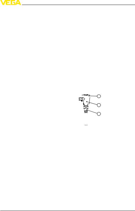
Constituent parts |
The VEGAVIB 61 consists of the components: |
|||||||||||
|
• |
Housing cover |
||||||||||
|
• Housing with electronics |
|||||||||||
|
• Process fitting with vibrating rod |
|||||||||||
|
|
|
|
|
|
|
|
|
|
|
|
|
|
|
|
|
|
|
|
1 |
|||||
|
|
|
|
|
|
|
|
|
|
|
|
|
|
|
|
|
|
|
|
|
|
|
|
|
|
|
|
|
|
|
|
|
|
|
|
|
|
|
|
|
|
|
|
|
|
|
|
|
|
2 |
|
|
|
|
|
|||||||||
|
|
|
|
|
|
|
|
|
|
|
|
|
|
|
|
|
|
|
|
|
|
|
|
|
|
|
|
|
|
|
|
|
|
|
|
|
3 |
|
|
|
|
|
|
|
|
|
|
|
|
||
|
|
|
|
|
|
|
|
|
|
|
|
|
|
|
|
|
|
|
|
|
|
|
|
|
|
29267-EN-120418
|
Fig. 1: VEGAVIB 61 - with plastic housing |
|
|
1 |
Housing cover |
|
2 |
Housing with electronics |
|
3 |
Process fitting |
Type label |
The type label contains the most important data for identification and |
|
|
use of the instrument: |
|
|
• |
Article number |
|
• |
Serial number |
|
• |
Technical data |
|
• |
Article numbers, documentation |
|
• |
SIL identification (with SIL rating ex works) |
With the serial number, you can access the delivery data of the instrument via www.vega.com, "VEGA Tools" and "serial number search". In addition to the type label outside, you can also find the serial number on the inside of the instrument.
VEGAVIB 61 • - transistor (NPN/PNP) |
7 |

3 Product description
|
3.2 Principle of operation |
Application area |
VEGAVIB 61 is a point level sensor with vibrating rod for level |
|
detection. |
|
It is designed for industrial use in all areas of process technology and |
|
is preferably used for bulk solids. |
|
Typical applications are overfill and dry run protection. Thanks to its |
|
simple and robust measuring system, VEGAVIB 61 is virtually |
|
una ected by the chemical and physical properties of the bulk solid. |
|
It also works when subjected to strong external vibrations or changing |
|
products. |
|
Solid detection in water |
|
If VEGAVIB 61 was ordered for solid detection in water, the vibrating |
|
rod is calibrated to the density of water. If covered by water (density: |
|
1 g/cm³/0.036 lbs/in) VEGAVIB 61 signals "uncovered". Only if the |
|
vibrating element is also covered with solids (e.g. sand, sludge, gravel |
|
etc.) will the sensor signal "covered". |
|
Fault monitoring |
|
The electronics module of VEGAVIB 61 monitors continuously the |
|
following criteria: |
|
• Correct vibrating frequency |
|
• Line break to the piezo drive |
|
If a malfunction is detected or in case of power failure, the electronics |
|
takes on a defined switching condition, i.e. the output is open (safe |
|
condition). |
Functional principle |
The vibrating rod is piezoelectrically energised and vibrates at its |
|
mechanical resonance frequency of approx. 360 Hz. When the |
|
vibrating rod is submerged in the product, the vibration amplitude |
|
changes. This change is detected by the integrated electronics module |
|
and converted into a switching command. |
Voltage supply |
VEGAVIB 61 is a compact instrument, i.e. it can be operated without |
|
external evaluation system. The integrated electronics evaluates the |
|
level signal and outputs a switching signal. With this switching signal, a |
|
connected device can be operated directly (e.g. a warning system, a |
|
pump etc.). |
|
The data for power supply are specified in chapter "Technical data". |
|
3.3 Operation |
|
With the factory setting, products with a density of > 0.05 g/cm³ |
|
(0.002 lbs/in³) can be measured. It is possible to adapt the instrument |
|
for products with lower density > 0.02 g/cm³ (0.0007 lbs/in³). |
|
On the electronics module you will find the following indicating and |
|
adjustment elements: |
|
|
8 |
VEGAVIB 61 • - transistor (NPN/PNP) |
120418-EN-29267

|
|
3 Product description |
|
|
• Signal lamp for indication of the switching condition (green/red) |
|
|
• Potentiometer for adaptation to the product density |
|
|
• Mode switch for selecting the switching condition (min./max.) |
|
|
3.4 Storage and transport |
Packaging |
Your instrument was protected by packaging during transport. Its |
|
|
|
capacity to handle normal loads during transport is assured by a test |
|
|
according to DIN EN 24180. |
|
|
The packaging of standard instruments consists of environment- |
|
|
friendly, recyclable cardboard. In addition, the sensor is provided with |
|
|
a protective cover of cardboard. For special versions PE foam or PE |
|
|
foil is also used. Dispose of the packaging material via specialised |
|
|
recycling companies. |
Transport |
Transport must be carried out under consideration of the notes on the |
|
|
|
transport packaging. Nonobservance of these instructions can cause |
|
|
damage to the device. |
Transport inspection |
The delivery must be checked for completeness and possible transit |
|
|
|
damage immediately at receipt. Ascertained transit damage or |
|
|
concealed defects must be appropriately dealt with. |
Storage |
Up to the time of installation, the packages must be left closed and |
|
|
|
stored according to the orientation and storage markings on the |
|
|
outside. |
|
|
Unless otherwise indicated, the packages must be stored only under |
|
|
the following conditions: |
|
|
• Not in the open |
|
|
• Dry and dust free |
|
|
• Not exposed to corrosive media |
|
|
• Protected against solar radiation |
|
|
• Avoiding mechanical shock and vibration |
Storage and transport |
• Storage and transport temperature see chapter "Supplement - |
|
temperature |
Technical data - Ambient conditions" |
|
|
|
• Relative humidity 20 … 85 % |
29267-EN-120418
VEGAVIB 61 • - transistor (NPN/PNP) |
9 |
4 Mounting
|
4 |
Mounting |
|
4.1 |
General instructions |
Suitability for the pro- |
Make sure that all parts of the instrument exposed to the process, in |
|
cess conditions |
particular the sensor element, process seal and process fitting, are |
|
|
suitable for the existing process conditions. These include above all |
|
|
the process pressure, process temperature as well as the chemical |
|
|
properties of the medium. |
|
|
You can find the specifications in chapter "Technical data" and on the |
|
|
type label. |
|
Switching point |
In general, VEGAVIB 61 can be installed in any position. The |
|
|
instrument only has to be mounted in such a way that the vibrating |
|
|
element is at the height of the desired switching point. |
|
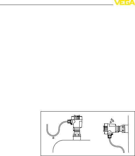
Moisture |
Use the recommended cables (see chapter "Connecting to power |
|
|
supply") and tighten the cable gland. |
|
You can give your instrument additional protection against moisture penetration by leading the connection cable downward in front of the cable entry. Rain and condensation water can thus drain o . This applies mainly to outdoor mounting as well as installation in areas where high humidity is expected (e.g. through cleaning processes) or on cooled or heated vessels.
|
Fig. 2: Measures against moisture penetration |
Transport |
Do not hold VEGAVIB 61 on the vibrating element. Especially with |
|
flange and tube versions, the sensor can be damaged by the weight of |
|
the instrument. |
|
Remove the protective cover just before mounting. |
Pressure/Vacuum |
The process fitting must be sealed if there is gauge or low pressure in |
|
the vessel. Before use, check if the seal material is resistant against |
|
the measured product and the process temperature. |
|
|
10 |
VEGAVIB 61 • - transistor (NPN/PNP) |
120418-EN-29267
|
4 Mounting |
|
The max. permissible pressure is specified in chapter "Technical data" |
|
or on the type label of the sensor. |
Handling |
The vibrating level switch is a measuring instrument and must be |
|
treated accordingly. Bending the vibrating element will destroy the |
|
instrument. |
|
Warning: |
|
The housing must not be used to screw the instrument in! Applying |
|
tightening force can damage internal parts of the housing. |
Use the hexagon above the thread for screwing in.
29267-EN-120418
Socket
Filling opening
4.2 Instructions for installation
The vibrating element should protrude into the vessel to avoid buildup. For that reason, avoid using mounting bosses for flanges and screwed fittings. This applies particularly to use with adhesive products.
Mount the instrument in such a way that the vibrating rod does not protrude directly into the filling stream.
a. |
b. |
|
20° |
Fig. 3: Horizontal installation |
|
aProtective sheet
bConcave protective sheet for abrasive solids
If such an installation location should be necessary, mount a suitable protective sheet above or in front of the vibrating element, see illustration "a").
In abrasive solids, mounting according to illustration "b" has proven. A spout forms in the concave protective sheet preventing wear of the protective sheet.
VEGAVIB 61 • - transistor (NPN/PNP) |
11 |
Loading...