


 Loading...
Operating Instructions
Radar sensor for continuous level measurement
VEGAPULS C 11
Two-wire 4 … 20 mA
Document ID: 58340

Contents
Contents
1 About this document................................................................................................................ |
4 |
|
1.1 |
Function............................................................................................................................ |
4 |
1.2 |
Target group...................................................................................................................... |
4 |
1.3 |
Symbols used................................................................................................................... |
4 |
2 For your safety.......................................................................................................................... |
5 |
|
2.1 |
Authorised personnel........................................................................................................ |
5 |
2.2 |
Appropriate use................................................................................................................ |
5 |
2.3 |
Warning about incorrect use............................................................................................. |
5 |
2.4 |
General safety instructions................................................................................................ |
5 |
2.5 |
EU conformity................................................................................................................... |
6 |
2.6 |
Installation and operation in the USA and Canada............................................................ |
6 |
2.7 |
Safety instructions for Ex areas......................................................................................... |
6 |
3 Product description.................................................................................................................. |
7 |
|
3.1 |
Configuration.................................................................................................................... |
7 |
3.2 |
Principle of operation........................................................................................................ |
8 |
3.3 |
Adjustment........................................................................................................................ |
8 |
3.4 |
Packaging, transport and storage..................................................................................... |
9 |
3.5 |
Accessories.................................................................................................................... |
10 |
4 Mounting.................................................................................................................................. |
11 |
|
4.1 |
General instructions........................................................................................................ |
11 |
4.2 |
Mounting versions........................................................................................................... |
11 |
4.3 |
Mounting instructions...................................................................................................... |
11 |
4.4 |
Measurement setup - Flow.............................................................................................. |
15 |
5 Connecting to power supply................................................................................................. |
17 |
|
5.1 |
Preparing the connection................................................................................................ |
17 |
5.2 |
Wiring plan...................................................................................................................... |
17 |
5.3 |
Switch-on phase............................................................................................................. |
18 |
6 |
Access protection................................................................................................................... |
19 |
||
|
6.1 |
Bluetooth radio interface................................................................................................. |
19 |
|
|
6.2 |
Protection of the parameterization.................................................................................. |
19 |
|
7 |
Setup with smartphone/tablet (Bluetooth).......................................................................... |
21 |
||
|
7.1 |
Preparations................................................................................................................... |
21 |
|
|
7.2 |
Connecting..................................................................................................................... |
21 |
|
|
7.3 |
Parameter adjustment..................................................................................................... |
22 |
|
8 |
Setup with PC/notebook (Bluetooth).................................................................................... |
23 |
||
|
8.1 |
Preparations................................................................................................................... |
23 |
|
|
8.2 |
Connecting..................................................................................................................... |
23 |
|
|
8.3 |
Parameter adjustment..................................................................................................... |
24 |
|
9 |
Menu overview........................................................................................................................ |
25 |
||
10 |
Diagnostics and servicing..................................................................................................... |
27 |
||
|
10.1 |
Maintenance................................................................................................................... |
27 |
|
|
10.2 |
Rectify faults................................................................................................................... |
27 |
|
|
10.3 |
Diagnosis, fault messages.............................................................................................. |
28 |
|
|
10.4 |
Status messages according to NE 107........................................................................... |
28 |
|
|
|
|
|
|
2 |
|
|
VEGAPULS C 11 • Two-wire 4 … 20 mA |
|
191014-EN-58340

58340-EN-191014
|
|
Contents |
10.5 |
Treatment of measurement errors................................................................................... |
31 |
10.6 |
Software update.............................................................................................................. |
34 |
10.7 |
How to proceed if a repair is necessary.......................................................................... |
35 |
11 Dismount................................................................................................................................. |
36 |
|
11.1 |
Dismounting steps.......................................................................................................... |
36 |
11.2 |
Disposal.......................................................................................................................... |
36 |
12 Certificates and approvals.................................................................................................... |
37 |
|
12.1 |
Radio license for Europe................................................................................................. |
37 |
12.2 |
Radio license for USA..................................................................................................... |
37 |
12.3 |
Radio license for Canada................................................................................................ |
38 |
12.4 |
Environmental instructions.............................................................................................. |
40 |
13 Supplement............................................................................................................................. |
41 |
|
13.1 |
Technical data................................................................................................................. |
41 |
13.2 |
Dimensions..................................................................................................................... |
45 |
13.3 |
Industrial property rights................................................................................................. |
46 |
13.4 |
Hash function acc. to mbed TLS..................................................................................... |
46 |
13.5 |
Trademark....................................................................................................................... |
46 |
Editing status: 2019-10-10
VEGAPULS C 11 • Two-wire 4 … 20 mA |
3 |
1 About this document
1 About this document
1.1Function
This instruction provides all the information you need for mounting, connection and setup as well as important instructions for maintenance, fault rectification, the exchange of parts and the safety of the user. Please read this information before putting the instrument into operation and keep this manual accessible in the immediate vicinity of the device.
1.2Target group
This operating instructions manual is directed to trained personnel.
The contents of this manual must be made available to the qualified personnel and implemented.
1.3Symbols used
Document ID
This symbol on the front page of this instruction refers to the Document ID. By entering the Document ID on www.vega.com you will reach the document download.
Information, note, tip: This symbol indicates helpful additional information and tips for successful work.
Note: This symbol indicates notes to prevent failures, malfunctions, damage to devices or plants.
Caution: Non-observance of the information marked with this symbol may result in personal injury.
Warning: Non-observance of the information marked with this symbol may result in serious or fatal personal injury.
Danger: Non-observance of the information marked with this symbol results in serious or fatal personal injury.
Ex applications
This symbol indicates special instructions for Ex applications.
•ListThe dot set in front indicates a list with no implied sequence.
1Sequence of actions
Numbers set in front indicate successive steps in a procedure.
Battery disposal
This symbol indicates special information about the disposal of batteries and accumulators.
191014-EN-58340
4 |
VEGAPULS C 11 • Two-wire 4 … 20 mA |

58340-EN-191014
2 For your safety
2 For your safety
2.1Authorised personnel
All operations described in this documentation must be carried out only by trained, qualified personnel authorised by the plant operator.
During work on and with the device, the required personal protective equipment must always be worn.
2.2Appropriate use
VEGAPULS C 11 is a sensor for continuous level measurement.
You can find detailed information about the area of application in chapter "Product description".
Operational reliability is ensured only if the instrument is properly used according to the specifications in the operating instructions manual as well as possible supplementary instructions.
2.3Warning about incorrect use
Inappropriate or incorrect use of this product can give rise to applica- tion-specific hazards, e.g.vessel overfill through incorrect mounting or adjustment. Damage to property and persons or environmental contamination can result. Also, the protective characteristics of the instrument can be impaired.
2.4General safety instructions
This is a state-of-the-art instrument complying with all prevailing regulations and directives. The instrument must only be operated in a technically flawless and reliable condition.The operator is responsible for the trouble-free operation of the instrument. When measuring aggressive or corrosive media that can cause a dangerous situation if the instrument malfunctions, the operator has to implement suitable measures to make sure the instrument is functioning properly.
During the entire duration of use, the user is obliged to determine the compliance of the necessary occupational safety measures with the current valid rules and regulations and also take note of new regulations.
The safety instructions in this operating instructions manual, the national installation standards as well as the valid safety regulations and accident prevention rules must be observed by the user.
For safety and warranty reasons, any invasive work on the device beyond that described in the operating instructions manual may be carried out only by personnel authorised by the manufacturer. Arbitrary conversions or modifications are explicitly forbidden.For safety reasons, only the accessory specified by the manufacturer must be used.
To avoid any danger, the safety approval markings and safety tips on the device must also be observed.
The low transmitting power of the radar sensor is far below the internationally approved limits. No health impairments are to be expected
VEGAPULS C 11 • Two-wire 4 … 20 mA |
5 |

2 For your safety
with intended use. The band range of the transmission frequency can be found in chapter "Technical data".
2.5EU conformity
The device fulfils the legal requirements of the applicable EU directives.By affixing the CE marking, we confirm the conformity of the instrument with these directives.
The EU conformity declaration can be found on our homepage.
2.6Installation and operation in the USA and Canada
This information is only valid for USA and Canada. Hence the following text is only available in the English language.
Installations in the US shall comply with the relevant requirements of the National Electrical Code (ANSI/NFPA 70).
Installations in Canada shall comply with the relevant requirements of the Canadian Electrical Code.
2.7Safety instructions for Ex areas
For Ex applications, only devices with corresponding Ex approval may be used.Observe the Ex-specific safety instructions.These are an integral part of the operating instructions and are enclosed with every device with Ex approval.
191014-EN-58340
6 |
VEGAPULS C 11 • Two-wire 4 … 20 mA |
58340-EN-191014
3 Product description
|
3 |
Product description |
|
3.1 Configuration |
|
Scope of delivery |
The scope of delivery encompasses: |
|
|
• |
VEGAPULS C 11 radar sensor |
|
• |
Information sheet "Documents and software" with: |
|
–– Instrument serial number |
|
|
• |
–– QR code with link for direct scanning |
|
Information sheet "PINs and Codes" with: |
|
|
–– Bluetooth access code |
|
|
• |
–– DataMatrix code with link for direct scanning |
|
Information sheet "Emergency unlock codes" with: |
|
|
–– Bluetooth access code |
|
|
|
–– Bluetooth unlock code |
|
|
–– Device unlock code |
|
Note: |
|
|
Optional instrument features are also described in this operating |
|
|
instructions manual. The respective scope of delivery results from the |
|
|
order specification. |
|
Scope of this operating |
This operating instructions manual applies to the following instrument |
|
instructions |
versions: |
|
|
• |
Hardware version from 1.0.0 |
Constituent parts |
• |
Software version from 1.0.0 |
|
5 |
|
|
|
|
|
|
4 |
|
|
3 |
|
|
2 |
|
|
1 |
|
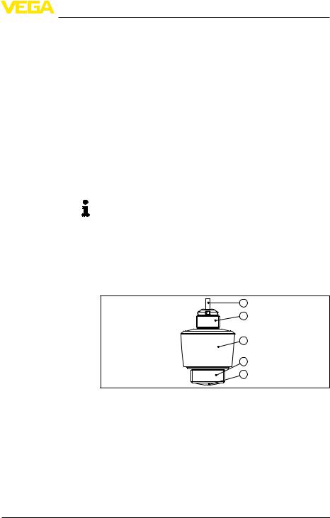
Fig. 1: Components of VEGAPULS C 11 |
|
|
1 |
Radar antenna |
|
2 |
Process fitting |
|
3 |
Electronics housing |
|
4 |
Mounting thread |
|
5 |
Connection cable |
Type label |
The type label contains the most important data for identification and |
|
|
use of the instrument. |
|
VEGAPULS C 11 • Two-wire 4 … 20 mA |
7 |
3 Product description
1 |
|
VEGAPULS C 1. |
s/n 12345678 |
6 |
||||||
|
|
|
|
|
|
|
|
|||
|
0044 |
|
|
|
|
|
|
|||
2 |
|
|
|
|
|
|
|
|
|
|
3 |
|
|
12...35V |
|
4...20mA |
MWP 3bar (300kPa) |
2019 |
|
5 |
|
|
|
|
|
|||||||
|
|
0...8m |
IP66/IP68, TYPE 6P |
PVDF |
www.vega.com |
|
||||
|
|
|
TAG1234 |
|
|
D-77761 SCHILTACH, |
|
|||
|
|
|
|
|
Made in Germany |
|
|
|
||
123456
4 |
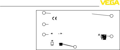
Fig. 2: Layout of the type label (example)
1Instrument type
2Field for approvals
3Technical data
4Number or DataMatrix code for Bluetooth access
5QR code for device documentation
6Serial number
Documents and software Move to "www.vega.com" and enter in the search field the serial number of your instrument.
There you can find the following information about the instrument:
•Order data
•Documentation
•Software
Alternatively, you can find all via your smartphone:
•Scan the QR-code on the type label of the device or
•Enter serial number manually in the VEGA Tools app (available free of charge in the respective stores)
|
3.2 Principle of operation |
Application area |
VEGAPULS C 11 is a radar sensor for continuous level measurement. |
|
It is suitable for liquids and solids in virtually all industries, particularly |
|
in the water and waste water industry. |
Functional principle |
The instrument emits a continuous, frequency-modulated radar signal |
|
through its antenna.The emitted signal is reflected by the medium |
|
and received by the antenna as an echo with modified frequency.The |
|
frequency change is proportional to the distance and is converted into |
|
the filling height. |
3.3 Adjustment
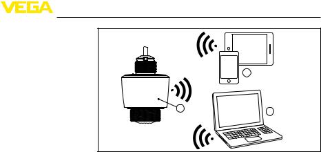
Wireless adjustment |
Devices with integrated Bluetooth module can be adjusted wirelessly |
||
|
via standard adjustment tools: |
||
|
• |
Smartphone/tablet (iOS or Android operating system) |
|
|
• |
PC/notebook with Bluetooth USB adapter (Windows operating |
|
|
|
system) |
|
|
|
|
|
8 |
|
VEGAPULS C 11 • Two-wire 4 … 20 mA |
|
191014-EN-58340
3 Product description
2
1 |
3 |
|
58340-EN-191014
Fig. 3: Wireless connection to standard operating devices with integrated
Bluetooth LE
1 |
Sensor |
2 |
Smartphone/Tablet |
3 |
PC/Notebook |
|
3.4 Packaging, transport and storage |
|
|
Packaging |
Your instrument was protected by packaging during transport. Its |
|
|
|
capacity to handle normal loads during transport is assured by a test |
||
|
based on ISO 4180. |
|
|
|
The packaging consists of environment-friendly, recyclable card- |
|
|
|
board. For special versions, PE foam or PE foil is also used. Dispose |
|
|
|
of the packaging material via specialised recycling companies. |
|
|
Transport |
Transport must be carried out in due consideration of the notes on the |
||
|
transport packaging. Nonobservance of these instructions can cause |
||
|
damage to the device. |
|
|
Transport inspection |
The delivery must be checked for completeness and possible transit |
|
|
|
damage immediately at receipt. Ascertained transit damage or con- |
|
|
|
cealed defects must be appropriately dealt with. |
|
|
Storage |
Up to the time of installation, the packages must be left closed and |
|
|
|
stored according to the orientation and storage markings on the |
|
|
|
outside. |
|
|
|
Unless otherwise indicated, the packages must be stored only under |
||
|
the following conditions: |
|
|
|
• |
Not in the open |
|
|
• |
Dry and dust free |
|
|
• |
Not exposed to corrosive media |
|
|
• |
Protected against solar radiation |
|
|
• |
Avoiding mechanical shock and vibration |
|
Storage and transport |
The permissible storage and transport temperatures can be found in |
|
|
temperature |
chapter "Supplement - Technical data - Ambient conditions" |
|
|
|
|
||
VEGAPULS C 11 • Two-wire 4 … 20 mA |
9 |
||

3 Product description
|
3.5 Accessories |
Flanges |
Screwed flanges are available in different versions according to the |
|
following standards: DIN 2501, EN 1092-1, BS 10, ASME B 16.5, |
|
JIS B 2210-1984, GOST 12821-80. |
Welded sockets and |
Welded sockets are used to connect the sensors to the process. |
adapters |
Threaded adapters enable simple adaptation of sensors with stand- |
|
ard threaded fittings, e.g.to process-side hygiene connections. |
Mounting accessories |
The mounting accessories include e.g. bracket and mounting bracket |
|
and are used for stable mounting of the sensor at the measuring |
|
point. The parts are available in various versions and sizes. |
191014-EN-58340
10 |
VEGAPULS C 11 • Two-wire 4 … 20 mA |
58340-EN-191014
Ambient conditions
Process conditions
Mounting bracket
Polarisation
4 Mounting
4 Mounting
4.1General instructions
The instrument is suitable for standard and extended ambient conditions acc. to DIN/EN/IEC/ANSI/ISA/UL/CSA 61010-1. It can be used indoors as well as outdoors.
Note:
For safety reasons, the instrument must only be operated within the permissible process conditions.You can find detailed information on the process conditions in chapter "Technical data" of the operating instructions or on the type label.
Hence make sure before mounting that all parts of the instrument exposed to the process are suitable for the existing process conditions.
These are mainly:
•Active measuring component
•Process fitting
•Process seal
Process conditions in particular are:
•Process pressure
•Process temperature
•Chemical properties of the medium
•Abrasion and mechanical influences
4.2Mounting versions
For a rigid mounting, a mounting bracket with opening for thread G1½, e.g. from the VEGA product range, is recommended. The mounting of the sensor in the bracket is carried out via a G1½ counter nut of plastic. Take note of chapter "Mounting instructions" for the recommended distance to the wall.
> 200 mm |
(7.87") |
Fig. 4: Mounting via a mounting bracket
4.3Mounting instructions
The emitted radar impulses of the radar sensor are electromagnetic waves. The polarisation is the direction of the electrical wave component. By turning the instrument in the mounting strap, the polarisation can be used to reduce the effects of false echoes.
VEGAPULS C 11 • Two-wire 4 … 20 mA |
11 |

4 Mounting
The position of the polarisation is in the middle of the type label on the instrument.
|
|
|
|
|
|
|
|
|
|
|
|
|
|
|
|
|
|
|
|
|
|
|
|
|
|
|
|
|
|
|
|
|
|
|
|
|
|
|
|
|
|
|
|
|
|
|
|
|
|
|
|
|
|
|
|
|
|
|
|
|
|
|
|
|
|
|
|
|
|
|
|
|
1 |
||||||||||||||||
|
|
|
|
|
|
|
|
|
|
|
|
|
|
|
|
|
|
|
|
|
|
|
|
|
|
|
|
|
|
|
|
|
|
|
|
|
|
|
|
|
|
|
|
|
|
|
|
|
|
|
|
||
|
Fig. 5: Position of the polarisation |
||||||||||||||||
|
1 Middle of the type label |
||||||||||||||||
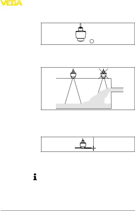
Installation position |
When mounting the sensor, keep a distance of at least 200 mm |
||||||||||||||||
|
(7.874 in) from the vessel wall. If the sensor is installed in the center |
||||||||||||||||
|
of dished or round vessel tops, multiple echoes can arise. However, |
||||||||||||||||
|
these can be suppressed by an appropriate adjustment (see chapter |
||||||||||||||||
|
"Setup"). |
||||||||||||||||
|
If you cannot maintain this distance, you should carry out a false |
||||||||||||||||
|
signal suppression during setup. This applies particularly if buildup on |
||||||||||||||||
|
the vessel wall is expected. In such cases, we recommend repeating |
||||||||||||||||
|
the false signal suppression at a later date with existing buildup. |
||||||||||||||||
|
|
|
|
|
|
|
|
|
|
|
|
|
|
|
|
|
|
|
|
|
|
|
|
|
|
|
|
|
|
|
|
|
|
|
|
|
|
|
|
|
|
|
|
|
|
|
|
|
|
|
|
|
|
|
|
|
|
|
|
|
|
|
|
|
|
|
|
|
|
|
|
> 200 mm  (7.87")
Fig. 6: Mounting of the radar sensor on round vessel tops
In vessels with conical bottom it can be advantageous to mount the sensor in the centre of the vessel, as measurement is then possible down to the bottom.
Fig. 7: Mounting of the radar sensor on vessels with conical bottom
12 |
VEGAPULS C 11 • Two-wire 4 … 20 mA |
191014-EN-58340
|
|
|
|
|
|
|
|
4 Mounting |
Reference plane |
The antenna edge of the device is the beginning of the measuring |
|||||||
|
|
range and at the same time the reference plane for the min./max. |
||||||
|
|
adjustment, see following diagram: |
||||||
|
|
|
|
|
|
|
|
|
|
|
|
|
|
|
|
|
|
|
|
|
|
|
|
|
|
|
|
|
|
|
|
|
|
|
|
58340-EN-191014
Inflowing medium
Mounting socket

 1
1
Fig. 8: Reference plane 1 Reference plane
Do not mount the instruments in or above the filling stream.Make sure that you detect the product surface, not the inflowing product.
Fig.9:Mounting of the radar sensor with inflowing medium
For socket mounting, the socket should be as short as possible and its end rounded.This reduces false reflections from the socket.
With threaded socket, the antenna end should protrude at least 5 mm (0.2 in) out of the socket.
ca. 5 mm |
Fig. 10: Recommended threaded socket mounting of VEGAPULS C 11
If the reflective properties of the medium are good, you can mount
VEGAPULS C 11 on sockets longer than the antenna. The socket end should be smooth and burr-free, if possible also rounded.
Note:
When mounting on longer sockets, we recommend carrying out a false signal suppression (see chapter "Parameter adjustment").
You will find recommended values for socket heights in the following illustration or the table. The values come from typical applications. Deviating from the proposed dimensions, also longer sockets are possible, however the local conditions must be taken into account.
VEGAPULS C 11 • Two-wire 4 … 20 mA |
13 |
4 Mounting
|
|
|
|
|
|
|
|
|
|
|
|
|
|
|
|
|
|
|
|
|
|
|
|
|
|
|
|
|
|
|
|
|
|
|
|
|
|
|
|
|
|
|
|
|
|
|
|
|
|
|
|
|
|
|
|
|
|
|
|
|
|
|
|
|
|
|
|
|
|
|
|
|
|
|
|
h |
|
|
|
|
|
|
|
|
|
|
|
|
|
|
|
|
|
|
|
|
|
|
|
|
|
|
|
|
|
|
|
|
d |
|
|
|
|
|
|
||||
|
|
|
|
|
|
|
|
|
|
|
|
|
|
|
|||||
|
Fig. 11: Socket mounting with deviating socket dimensions |
|
|||||||||||||||||
|
|
|
|
|
|
|
|
|
|
|
|
|
|
|
|
||||
|
Socket diameter d |
|
|
|
|
|
|
|
|
|
|
|
Socket length h |
|
|||||
|
40 mm |
|
1½" |
|
|
|
|
|
|
|
|
|
|
≤ 150 mm |
≤ 5.9 in |
||||
|
50 mm |
|
2" |
|
|
|
|
|
|
|
|
|
|
≤ 200 mm |
≤ 7.9 in |
||||
|
80 mm |
|
3" |
|
|
|
|
|
|
|
|
|
|
≤ 300 mm |
≤ 11.8 in |
||||
|
100 mm |
|
4" |
|
|
|
|
|
|
|
|
|
|
≤ 400 mm |
≤ 15.8 in |
||||
|
150 mm |
|
6" |
|
|
|
|
|
|
|
|
|
|
≤ 600 mm |
≤ 23.6 in |
||||
Vessel installations |
The mounting location of the radar sensor should be a place where no |
||||||||||||||||||
|
other equipment or fixtures cross the path of the radar signals. |
||||||||||||||||||
Vessel installations, such as e.g. ladders, limit switches, heating spirals, struts, etc., can cause false echoes and impair the useful echo. Make sure when planning your measuring point that the radar sensor has a "clear view" to the measured product.
In case of existing vessel installations, a false signal suppression should be carried out during setup.
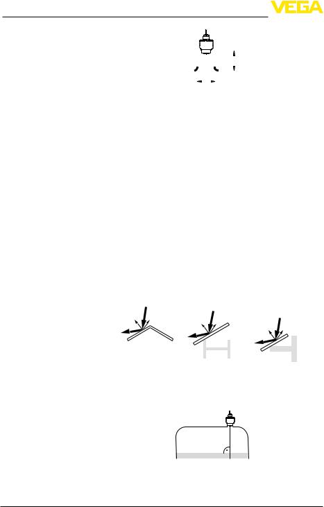
If large vessel installations such as struts or supports cause false echoes, these can be attenuated through supplementary measures.
Small, inclined sheet metal baffles above the installations scatter the radar signals and prevent direct interfering reflections.
|
|
|
|
|
|
|
|
|
|
|
|
|
|
|
|
|
|
|
|
|
|
|
|
|
|
|
|
|
|
|
|
|
|
|
|
|
|
|
|
|
|
|
|
|
|
|
|
|
|
|
|
|
|
|
|
|
|
|
|
|
|
|
|
|
|
|
|
|
|
|
|
|
|
|
|
|
|
|
|
|
|
|
|
|
Fig.12:Cover flat, large-area profiles with deflectors |
||||||||||||
Sensor orientation |
In liquids, direct the sensor as perpendicular as possible to the prod- |
||||||||||||
|
uct surface to achieve optimum measurement results. |
||||||||||||
|
|
|
|
|
|
|
|
|
|
|
|
|
|
|
|
|
|
|
|
|
|
|
|
|
|
|
|
|
|
|
|
|
|
|
|
|
|
|
|
|
|
|
|
|
|
|
|
|
|
|
|
|
|
|
|
|
|
|
|
|
|
|
|
|
|
|
|
|
|
Fig. 13: Alignment in liquids
14 |
VEGAPULS C 11 • Two-wire 4 … 20 mA |
191014-EN-58340

|
|
|
|
|
|
|
|
|
|
|
|
|
|
4 Mounting |
Agitators |
If there are agitators in the vessel, a false signal suppression should |
|||||||||||||
|
be carried out with the agitators in motion. This ensures that the |
|||||||||||||
|
interfering reflections from the agitators are saved with the blades in |
|||||||||||||
|
different positions. |
|||||||||||||
|
|
|
|
|
|
|
|
|
|
|
|
|
|
|
|
|
|
|
|
|
|
|
|
|
|
|
|
|
|
|
|
|
|
|
|
|
|
|
|
|
|
|
|
|
|
|
|
|
|
|
|
|
|
|
|
|
|
|
|
|
|
|
|
|
|
|
|
|
|
|
|
|
|
|
|
|
|
|
|
|
|
|
|
|
|
|
|
|
|
|
|
|
|
|
|
|
|
|
|
|
|
|
|
|
|
|
|
|
|
|
|
|
|
|
|
|
|
|
|
|
|
|
|
|
|
|
|
|
|
|
|
|
|
|
|
|
|
|
|
|
|
|
|
|
|
|
|
|
|
|
|
|
|
|
|
|
|
|
|
|
|
|
|
|
|
|
|
|
|
|
|
|
|
|
|
|
|
|
|
|
|
|
|
|
|
|
|
|
|
|
|
|
|
|
58340-EN-191014
|
Fig. 14: Agitators |
|
Foam generation |
Through the action of filling, stirring and other processes in the vessel, |
|
|
compact foams which considerably damp the emitted signals may |
|
|
form on the product surface. |
|
|
If foams lead to measurement errors, you should use the biggest pos- |
|
|
sible radar antennas or sensors with guided radar. |
|
|
4.4 Measurement setup - Flow |
|
|
In general, the following must be observed while mounting the sensor: |
|
|
• |
Mounting the sensor on the upstream or inlet side |
|
• |
surfaceInstallation in the centre of the flume and vertical to the liquid |
|
• |
Distance to the overfall orifice orVenturi flume |
|
• |
Min. distance to the max. height of damming for optimum accu- |
|
racy: 250 mm (9.843 in)1) |
|
Detailed project planning data can be found at the channel manufacturers and in the technical literature.
The measurement can be individually configured for the respective flume via a PC/notebook and PACTware/DTM.The measurement can be individually configured for the respective flume via a PC/notebook and PACTware/DTM.
The following examples serve as an overview for flow measurement.
1) At smaller distances the measuring accuracy is reduced, see Technical data.
VEGAPULS C 11 • Two-wire 4 … 20 mA |
15 |
Loading...