


 Loading...
Operating Instructions
Signal conditioning and display instrument for level sensors
VEGAMET 391
4 … 20 mA/HART
Document ID: 36032

Contents
Contents
1 About this document |
4 |
|
1.1 |
Function............................................................................................................................ |
|
1.2 |
Target group...................................................................................................................... |
4 |
1.3 |
Symbolism used............................................................................................................... |
4 |
2 For your safety |
5 |
|
2.1 |
Authorised personnel........................................................................................................ |
|
2.2 |
Appropriate use................................................................................................................ |
5 |
2.3 |
Warning about incorrect use............................................................................................. |
5 |
2.4 |
General safety instructions................................................................................................ |
5 |
2.5 |
Safety label on the instrument........................................................................................... |
5 |
2.6 |
CE conformity................................................................................................................... |
6 |
2.7 |
Safety instructions for Ex areas......................................................................................... |
6 |
2.8 |
Overfill protection according toWHG................................................................................ |
6 |
2.9 |
Environmental instructions................................................................................................ |
6 |
3 Product description |
7 |
|
3.1 |
Configuration.................................................................................................................... |
|
3.2 |
Principle of operation........................................................................................................ |
8 |
3.3 |
Adjustment........................................................................................................................ |
8 |
3.4 |
Packaging, transport and storage..................................................................................... |
8 |
4 |
Mounting |
10 |
|
|
4.1 |
General instructions........................................................................................................ |
|
|
4.2 |
Mounting instructions...................................................................................................... |
10 |
5 |
Connecting to power supply |
13 |
|
|
5.1 |
Preparing the connection................................................................................................ |
|
|
5.2 |
Connection procedure.................................................................................................... |
13 |
|
5.3 |
Wiring plan...................................................................................................................... |
15 |
6 |
Setup with the integrated display and adjustment unit |
17 |
|
|
6.1 |
Adjustment system.......................................................................................................... |
|
|
6.2 |
Setup steps..................................................................................................................... |
18 |
|
6.3 |
Menu schematic............................................................................................................. |
28 |
7 |
Setup with PACTware |
35 |
|
|
7.1 |
Connect the PC............................................................................................................... |
|
|
7.2 |
Parameter adjustment with PACTware............................................................................ |
37 |
|
7.3 |
Setup web server/e-mail, remote enquiry........................................................................ |
38 |
8 |
Application examples |
39 |
|
|
8.1 |
Level measurement in a cylindrical tank with overfill protection/dry run protection.......... |
|
|
8.2 |
Pump control 1/2 (running time controlled)..................................................................... |
40 |
|
8.3 |
Pump control 3/4 (sequentially controlled)...................................................................... |
43 |
|
8.4 |
Tendency recognition...................................................................................................... |
45 |
|
8.5 |
Flow measurement......................................................................................................... |
47 |
9Maintenance and fault rectification
9.1 |
Maintenance................................................................................................................... |
49 |
|
9.2 |
Rectify faults................................................................................................................... |
49 |
|
9.3 |
Instrument repair............................................................................................................. |
51 |
|
|
|
|
|
2 |
|
VEGAMET 391 • 4 … 20 mA/HART |
|
130701-EN-36032

36032-EN-130701
|
|
|
|
Contents |
|
10 |
Dismounting |
52 |
|||
|
10.1 |
Dismounting steps.......................................................................................................... |
|||
|
10.2 |
Disposal.......................................................................................................................... |
52 |
||
11 |
Supplement |
53 |
|||
|
11.1 |
Technical data................................................................................................................. |
|||
|
11.2 |
Overview applications/functionality................................................................................. |
56 |
||
|
11.3 |
Dimensions..................................................................................................................... |
57 |
||
Supplementary documentation
Information:
Supplementary documents appropriate to the ordered version come with the delivery.You can find them listed in chapter "Product description".
Editing status: 2013-06-18
VEGAMET 391 • 4 … 20 mA/HART |
3 |
1 About this document
1 About this document
1.1Function
This operating instructions manual provides all the information you need for mounting, connection and setup as well as important instructions for maintenance and fault rectification.Please read this information before putting the instrument into operation and keep this manual accessible in the immediate vicinity of the device.
1.2Target group
This operating instructions manual is directed to trained specialist personnel. The contents of this manual should be made available to these personnel and put into practice by them.
1.3Symbolism used
•
→
Information, tip, note
This symbol indicates helpful additional information.
Caution: If this warning is ignored, faults or malfunctions can result.
Warning: If this warning is ignored, injury to persons and/or serious damage to the instrument can result.
Danger: If this warning is ignored, serious injury to persons and/or destruction of the instrument can result.
Ex applications
This symbol indicates special instructions for Ex applications.
List
The dot set in front indicates a list with no implied sequence.
Action
This arrow indicates a single action.
1Sequence of actions
Numbers set in front indicate successive steps in a procedure.
Battery disposal
This symbol indicates special information about the disposal of batteries and accumulators.
130701-EN-36032
4 |
VEGAMET 391 • 4 … 20 mA/HART |

36032-EN-130701
2 For your safety
2 For your safety
2.1Authorised personnel
All operations described in this operating instructions manual must be carried out only by trained specialist personnel authorised by the plant operator.
During work on and with the device the required personal protective equipment must always be worn.
2.2Appropriate use
VEGAMET 391 is a universal signal conditioning instrument and power supply unit for connection of a 4 … 20 mA/HART sensor.
You can find detailed information on the application range in chapter "Product description".
Operational reliability is ensured only if the instrument is properly used according to the specifications in the operating instructions manual as well as possible supplementary instructions.
For safety and warranty reasons, any invasive work on the device beyond that described in the operating instructions manual may be carried out only by personnel authorised by the manufacturer. Arbitrary conversions or modifications are explicitly forbidden.
2.3Warning about incorrect use
Inappropriate or incorrect use of the instrument can give rise to application-specific hazards, e.g.vessel overfill or damage to system components through incorrect mounting or adjustment.
2.4General safety instructions
This is a high-tech instrument requiring the strict observance of standard regulations and guidelines. The user must take note of the safety instructions in this operating instructions manual, the country-specific installation standards as well as all prevailing safety regulations and accident prevention rules.
The instrument must only be operated in a technically flawless and reliable condition. The operator is responsible for trouble-free operation of the instrument.
During the entire duration of use, the user is obliged to determine the compliance of the necessary occupational safety measures with the current valid rules and regulations and also take note of new regulations.
2.5Safety label on the instrument
The safety approval markings and safety tips on the device must be observed.
VEGAMET 391 • 4 … 20 mA/HART |
5 |

2 For your safety
2.6CE conformity
The device fulfills the legal requirements of the applicable EC guidelines.By affixing the CE marking, we confirm successful testing of the product.
You can find the CE Certificate of Conformity in the download section of our homepage.
Electromagnetic compatibility
The instrument is designed for use in an industrial environment. Nevertheless, electromagnetic interference from electrical conductors and radiated emissions must be taken into account, as is usual with a class A instrument according to EN 61326-1. If the instrument is used in a different environment, its electromagnetic compatibility with other devices must be ensured by suitable measures.
2.7Safety instructions for Ex areas
Please note the Ex-specific safety information for installation and operation in Ex areas. These safety instructions are part of the operating instructions manual and come with the Ex-approved instruments.
2.8Overfill protection according to WHG
In Germany theWHG (Water Resource Act) stipulates an overfill protection for systems that deal with substances hazardous to water. An appropriately certified sensor is the prerequisite for such protection.TheVEGAMET 391 fulfils the construction and testing principles for overfill protection systems.This is certified by theTÜV (Technical Control Board) statement "PP 5003/09".You can download this document from our homepage under "Downloads - Approvals - Signal conditioning instruments - Overfill protection".
2.9Environmental instructions
Protection of the environment is one of our most important duties. That is why we have introduced an environment management system with the goal of continuously improving company environmental protection.The environment management system is certified according to DIN EN ISO 14001.
Please help us fulfill this obligation by observing the environmental instructions in this manual:
•Chapter "Packaging, transport and storage"
•Chapter "Disposal"
130701-EN-36032
6 |
VEGAMET 391 • 4 … 20 mA/HART |
36032-EN-130701
Scope of delivery
Constituent parts
Type plate
3 Product description
3 Product description
3.1Configuration
The scope of delivery encompasses:
•VEGAMET 391 signal conditioning instrument
•Two clamping elements for panel mounting
•Ex separating wall
•Mini-USB cable
•Carrier rail adapter (optional)
•RS232 modem connection cable (optional)
•Documentation
––this operating instructions manual
––Supplementary instruction 30325 "RS232/Ethernet connection"
(optional)
––Supplementary instructions manual 30768 "Modbus-TCP, ASCII protocol" (optional)
––Ex-specific "Safety instructions" (with Ex-version)
––if necessary, further certificates
|
2 |
1 |
|
|
|
|
|
2 |
|
|
|
|
|
|
|
|
|
|
|
VEGAMET 391 |
|
|
|
|
|
|
|
|
|
|
|
|
|
|
3 |
|
|
|
1 |
2 |
3 |
4 |
5 |
6 |
|
|
on |
ESC |
|
|
|
OK |
|
|
|
|
|
|
|
|
|
|
5 |
4 |
|
|
|
|
|
|
|
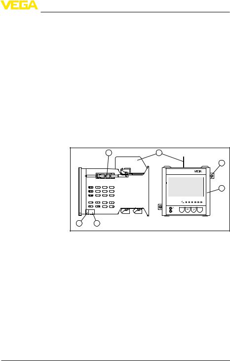
Fig. 1: VEGAMET 391
1Ex separating wall
2Clamping element for panel mounting
3Display and adjustment unit
4RS232 or Ethernet interface (optional)
5USB interface
The nameplate contains the most important data for identification and use of the instrument:
•Article number
•Serial number
•Technical data
•Article numbers, documentation
The order data and the documentation of the instrument can be retrieved by means of the instrument serial number on the type label. To do this, go to www.vega.com, "VEGA Tools" and "serial number search".
VEGAMET 391 • 4 … 20 mA/HART |
7 |

3 Product description
|
3.2 Principle of operation |
Application area |
VEGAMET 391 is a universal signal conditioning instrument for a |
|
variety of applications such as level, gauge and process pressure |
|
measurement. At the same time, it can serve as power supply unit for |
|
connected sensors. VEGAMET 391 is designed for connection of any |
|
4 … 20 mA/HART sensor. |
|
On instruments with one of the optional interfaces (RS232/Ethernet), |
|
the measured values can be retrieved via modem or network and |
|
displayed by means of a web browser or WEB-VV. It is also possible |
|
to send measured values and messages via e-mail/SMS. The use of |
|
VEGAMET 391 is particularly suitable for stocktaking, VMI (Vendor |
|
Managed Inventory) and remote enquiry. |
Functional principle |
The VEGAMET 391 signal conditioning instrument can power the |
|
connected sensor and process its measurement signals. The re- |
|
quested parameter is shown on the display and also outputted to the |
|
integrated current output for further processing. The measurement |
|
signal can thus be transferred to a remote indication or a superordi- |
|
nate control system. Operating relays for control of pumps or other |
|
devices are also integrated. |
Voltage supply |
Wide-range power supply unit with 20 … 253 V AC/DC for world-wide |
|
use. |
|
Detailed information about the power supply can be found in chapter |
|
"Technical data". |
3.3 Adjustment
|
|
|
|
The instrument can be adjusted with the following adjustment media: |
||
|
|
|
|
• |
With integrated display and adjustment unit |
|
|
|
|
|
• |
an adjustment software according to FDT/DTM standard, e.g. |
|
|
|
|
|
|
PACTware and a Windows PC |
|
|
|
|
|
The entered parameters are generally saved in VEGAMET 391, when |
||
|
|
|
|
used with PACTware and PC also optionally in the PC. |
||
|
|
|
|
Information: |
||
|
|
|
|
When using PACTware and the respective DTM, additional settings |
||
|
|
|
|
can be carried out which are not possible or only partly possible with |
||
|
|
|
|
the integrated display and adjustment unit. Communication is carried |
||
|
|
|
|
out via the integrated USB interface or one of the optional interfaces |
||
|
|
|
|
(RS232/Ethernet). |
||
|
|
|
|
Further instructions for setting up the web server and e-mail functions |
||
|
|
|
|
can be found in the online help of PACTware or the VEGAMET 391 |
||
|
|
|
|
DTMs as well as the operating instructions manual "RS232/Ethernet |
||
|
|
|
|
connection". |
||
|
|
|
|
3.4 Packaging, transport and storage |
||
Packaging |
|
|
Your instrument was protected by packaging during transport. Its |
|||
|
|
|
|
capacity to handle normal loads during transport is assured by a test |
||
|
|
|
|
based on ISO 4180. |
||
|
|
|
|
|
|
|
8 |
|
|
|
|
VEGAMET 391 • 4 … 20 mA/HART |
|
130701-EN-36032

|
|
|
3 Product description |
|
|
The packaging of standard instruments consists of environment- |
|
|
|
friendly, recyclable cardboard. For special versions, PE foam or PE |
|
|
|
foil is also used. Dispose of the packaging material via specialised |
|
|
|
recycling companies. |
|
Transport |
Transport must be carried out under consideration of the notes on the |
||
|
|
transport packaging. Nonobservance of these instructions can cause |
|
|
|
damage to the device. |
|
Transport inspection |
The delivery must be checked for completeness and possible transit |
||
|
|
damage immediately at receipt. Ascertained transit damage or con- |
|
|
|
cealed defects must be appropriately dealt with. |
|
Storage |
Up to the time of installation, the packages must be left closed and |
||
|
|
stored according to the orientation and storage markings on the |
|
|
|
outside. |
|
|
|
Unless otherwise indicated, the packages must be stored only under |
|
|
|
the following conditions: |
|
|
|
• |
Not in the open |
|
|
• |
Dry and dust free |
|
|
• |
Not exposed to corrosive media |
|
|
• |
Protected against solar radiation |
|
|
• |
Avoiding mechanical shock and vibration |
Storage and transport |
• |
Storage and transport temperature see chapter "Supplement - |
|
temperature |
Technical data - Ambient conditions" |
||
|
|
• |
Relative humidity 20 … 85 % |
36032-EN-130701
VEGAMET 391 • 4 … 20 mA/HART |
9 |

4 Mounting
4 Mounting
4.1General instructions
Installation possibilities The instrument is designed for recessed installation in an instrument panel, housing front plate or a switching cabinet door. The required cut-out is 92 x 92 mm (3.63 x 3.63 in) according to EN 60529. When installed correctly, protection rating IP 65 is guaranteed. As an alternative, the instrument can be mounted in a switching cabinet or protective housing by means of four screws (fixed with screws on rear of housing). A mounting adapter for carrier rail mounting is available as an option (top hat rail 35 x 7.5 according to DIN EN 50022/60715).
Note:
If the instrument is mounted via the screws or carrier rail, it must
always be inside a switching cabinet or protective case.
A VEGAMET 391 in Ex version is an auxiliary, intrinsically safe instrument and may not be installed in explosion-endangered areas.
Before setup, the Ex separating wall must be attached to Ex versions. Safe operation can only be ensured if the operating instructions manual and the EC type approval certificate are observed.VEGAMET
391 must not be opened.
4.2Mounting instructions
Front panel mounting 1. Make sure that the cut-out required for mounting has a size of
92 x 92 mm (3.63 x 3.63 in).
2.Check for the correct position of the seal directly behind the front plate and insert the instrument from the front into the front panel cut-out.
3.Press the two tensioning elements into the provided gaps.
4.Screw in the two screws of the tensioning elements evenly with a screwdriver.
130701-EN-36032
10 |
VEGAMET 391 • 4 … 20 mA/HART |

36032-EN-130701
4 Mounting
1 |
2 |
3 |
Fig. 2: Front panel mounting
1Front panel, front plate or switching cabinet door
2Clamping elements
3Slotted screw
Screw mounting |
Fasten the instrument by means of four screws (max. ø 4 mm) on |
|
→ the inner side of the housing or the mounting plate according to |
|
the following illustration. |
1 |
mm |
(3.41") |
86,5 |
73 mm |
(2.87") |
2 |
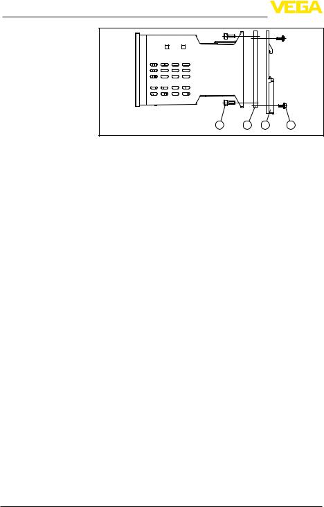
Fig. 3: Screw mounting
1Fixing screw
2Rear of the housing or mounting plate
Carrier rail mounting 1. Fasten the mounting plate to the instrument with the four attached hexagon screws.
2.Screw the carrier rail adapter to the mounting plate by using the four attached Phillips head screws.
VEGAMET 391 • 4 … 20 mA/HART |
11 |
4 Mounting
1 |
2 |
3 |
4 |
Fig. 4: Carrier rail mounting
1Hexagon screws
2Mounting plate
3Carrier rail adapter
4Phillips head screws
130701-EN-36032
12 |
VEGAMET 391 • 4 … 20 mA/HART |
36032-EN-130701
5 Connecting to power supply
5 Connecting to power supply
5.1Preparing the connection
Note safety instructions Always keep in mind the following safety instructions:
•Connect only in the complete absence of line voltage
•If overvoltage surges are expected, overvoltage arresters should be installed
Take note of safety instructions for Ex applications
Select power supply Select connection cable
Cable screening and grounding
Select connection cable for Ex applications
In hazardous areas you must take note of the respective regulations, conformity and type approval certificates of the sensors and power supply units.
The voltage supply can be 20 … 253V AC/DC, 50/60 Hz.
The operating voltage of VEGAMET 391 is connected with standard cable according to the national installation standards.
Standard two-wire cable can be used for connecting the sensors. The screening is absolutely necessary to ensure interference-free operation with HART sensors.
Connect the cable screen on both ends to ground potential. In the sensor, the screen must be connected directly to the internal ground terminal. The ground terminal on the outside of the sensor housing must be connected to the potential equalisation (low impedance).
If potential equalisation currents are expected, the screen connection on the side of VEGAMET 391 must be made via a ceramic capacitor (e. g. 1 nF, 1500 V). The low frequency potential equalisation currents are thus suppressed, but the protective effect against high frequency interference signals remains.
Take note of the corresponding installation regulations for Ex applications. In particular, make sure that no potential equalisation currents flow over the cable screen.In case of grounding on both sides this can be achieved by the use of a capacitor or a separate potential equalisation.
5.2Connection procedure
Move on to electrical connection and proceed as follows:
1.Mount the instrument as described in the previous chapter
2.Remove terminal strip 1 on the upper side of the instrument
3.Connect sensor cable to terminal 1/2 (active input) or 5/6 (passive input)
4.If necessary, connect digital inputs to 8 … 12
5.Plug terminal strip 1 to the upper side of the instrument
6.Remove terminal strip 2 on the lower side of the instrument
7.Connect power supply (switched off) to terminal 13/14
8.If necessary, connect relays or other outputs
9.Plug in terminal strip 2 on the lower side of the instrument
VEGAMET 391 • 4 … 20 mA/HART |
13 |

5 Connecting to power supply
10.For connection of additional relais to terminal strip 3, you have to proceed as described earlier
The electrical connection is hence finished.
Remember that with Ex applications, the Ex separating wall must be plugged onto the upper side of the instrument before setup.
Information:
|
|
|
• |
On the active input (terminal 1/2), VEGAMET 391 provides power |
|
|
|
||
|
|
|
for the connected sensors. Power supply and measurement data |
|
|
|
|
||
|
|
|
|
are transmitted over the same two-wire cable. This mode is pro- |
|
|
|
|
vided for connection of measuring transducers without separate |
|
|
|
• |
operating voltage (sensors in two-wire version). |
|
|
|
On the passive input (terminals 5/6), the sensors are not powered |
|
|
|
|
- only the measured value is transmitted. This input is for sensors |
|
|
|
|
|
with their own, separate operating voltage (sensors in four-wire |
|
|
|
|
version). On a VEGAMET 391 in Ex version, the passive input is |
|
|
|
|
not available due approval-technical reasons. |
130701-EN-36032
14 |
VEGAMET 391 • 4 … 20 mA/HART |
5 Connecting to power supply
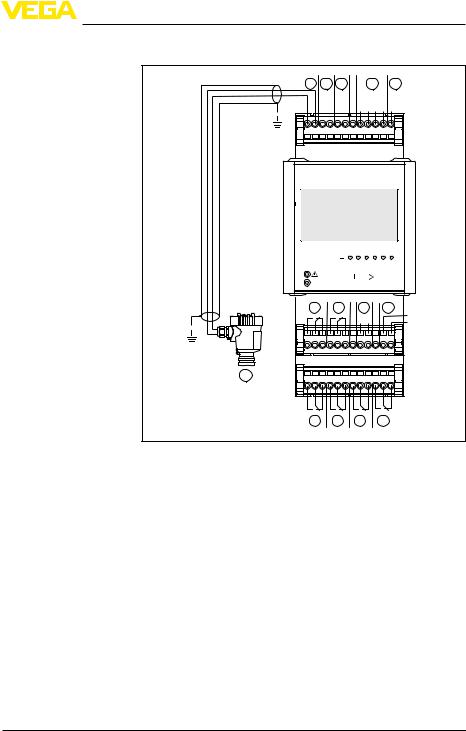
5.3Wiring plan
Wiring plan for two-wire |
|
|
|
|
|
|
|
|
|
|
sensor |
9 |
10 11 |
|
|
12 |
13 |
||||
|
|
|
||||||||
|
+ |
- |
|
|
|
|
|
+ + + + - |
||
|
1 |
2 |
3 |
4 |
5 |
6 |
7 |
8 |
9 10 11 12 |
|
|
|
1 |
2 |
3 |
4 |
5 |
6 |
|
|
on |
ESC |
|
|
|
OK |
|
|
|
|
|
|
|
|
|
|
|
|
2 |
1 |
7 |
|
|
8 |
N- |
|
|
|
|
- |
+ |
|
|
|
L+ |
|
24 23 22 21 20 19 18 17 16 15 14 13 |
|
||||||
14 |
36 35 34 33 32 31 30 29 28 27 26 25 |
|
||||||
6 5 4 3
Fig. 5: Wiring plan with two-wire sensor
1Relay 1
2Relay 2
3Relay 3
4Relay 4
5Relay 5
6Relay 6
7Current output
8Operating voltage of the signal conditioning instrument
9Measurement data input with sensor supply (active input)
10Connection for HART modem for sensor parameter adjustment
11Measurement data input (passive input), not with Ex-ia version
12Digital input 1 … 4
13Common ground for digital input 1 … 4
144 … 20 mA/HART sensor (two-wire version)
36032-EN-130701
VEGAMET 391 • 4 … 20 mA/HART |
15 |
5 Connecting to power supply
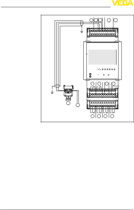
Wiring plan for four-wire sensor
16
|
|
9 |
10 11 |
|
|
12 |
|
13 |
|
|||||
|
|
|
|
|
|
+ |
- |
|
+ + + + - |
|
||||
|
|
1 |
2 |
3 |
4 |
5 |
6 |
7 |
8 |
9 10 11 12 |
|
|||
|
|
|
|
|
|
|
|
1 |
2 |
3 |
4 |
5 |
6 |
|
|
|
|
on |
|
|
ESC |
|
|
|
|
OK |
|
||
|
|
|
|
|
|
|
|
|
|
|
|
|
|
|
|
|
|
2 |
|
|
1 |
|
|
7 |
|
|
8 |
N- |
|
|
|
|
|
|
|
|
|
|
- |
+ |
|
|
|
L+ |
|
|
24 23 22 21 20 19 18 17 16 15 14 13 |
|
|||||||||||
14 |
15 |
36 35 34 33 32 31 30 29 28 27 26 25 |
|
|||||||||||
|
|
|
|
|
|
|
|
|
|
|
|
|
|
|
|
|
|
6 |
|
|
5 |
|
|
4 |
|
|
3 |
|
|
Fig. 6: Terminal assignment with four-wire sensor
1Relay 1
2Relay 2
3Relay 3
4Relay 4
5Relay 5
6Relay 6
7Current output
8Operating voltage of the signal conditioning instrument
9Measurement data input with sensor supply (active input)
10Connection for HART modem for sensor parameter adjustment
11Measurement data input (passive input), not with Ex-ia version
12Digital input 1 … 4
13Common ground for digital input 1 … 4
144 … 20 mA/HART sensor (four-wire version)
15Power supply for four-wire sensor
130701-EN-36032
VEGAMET 391 • 4 … 20 mA/HART
36032-EN-130701
|
|
6 Setup with the integrated display and adjustment unit |
|
|||||
|
|
6 Setup with the integrated display and |
||||||
|
|
adjustment unit |
||||||
|
|
6.1 Adjustment system |
||||||
Function |
The integrated display and adjustment unit is used for measured |
|||||||
|
|
value display, adjustment and diagnosis of VEGAMET 391. The |
||||||
|
|
indication and adjustment are carried out via four keys and a clear, |
||||||
|
|
graphic-capable display with background lighting. The adjustment |
||||||
|
|
menu with selectable language is clearly structured and enables easy |
||||||
|
|
setup. |
||||||
|
|
Certain adjustment options are not available or only partially available |
||||||
|
|
with the integrated display and adjustment unit, e.g. the settings for |
||||||
|
|
flow measurement.For such applications, the use of PACTware with |
||||||
Display and adjustment |
appropriate DTMs is recommended. |
|||||||
|
|
|
|
|
|
|
||
elements |
|
|
|
|
|
|
|
|
|
|
VEGAMET 391 |
||||||
|
|
|
|
|||||
|
|
|
|
|
|
|
|
|
|
|
|
|
|
1 |
|
||
|
|
|
|
|||||
5 |
1 |
2 |
3 |
4 |
5 |
6 |
|
||||||
4 |
|
|
|
|
|
2 |
on ESC |
|
|
|
OK |
||
3 |
|
|
|
|
|
|
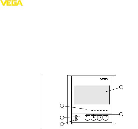
Fig. 7: Display and adjustment elements
1LC display
2Adjustment keys
3Status indication operation
4Status indication fail safe relay
5Status indication operating relay 1 … 6
Key functions |
• |
[OK] key: |
|
|
–– Move to the menu overview |
||
|
|
–– |
Confirm selected menu |
|
|
–– Edit parameter |
|
|
• |
–– Save value |
|
|
[->] key to select: |
||
|
–– Menu change |
||
|
|
–– |
Select list entry |
|
• |
–– |
Select editing position |
|
[+] key: |
||
|
• |
–– Change value of the parameter |
|
|
[ESC] key: |
||
|
|
–– |
Interrupt input |
|
|
||
VEGAMET 391 • 4 … 20 mA/HART |
17 |
||
6 Setup with the integrated display and adjustment unit
–– Jump to next higher menu
|
|
|
|
Note: |
||
|
|
|
|
Approx. 10 minutes after the last pressing of a key, an automatic reset |
||
|
|
|
|
to measured value indication is triggered.Any values not confirmed |
||
|
|
|
|
|||
|
|
|
|
with [OK] will not be saved. |
||
|
|
|
|
6.2 Setup steps |
||
Parameter adjustment |
|
Through parameter adjustment, the instrument is adapted to the indi- |
||||
|
|
|
|
vidual application conditions. A measurement loop calibration is the |
||
|
|
|
|
most important step and should always be carried out. A scaling of |
||
|
|
|
|
the measured value to the desired physical variable and unit, possibly |
||
|
|
|
|
including a linearization curve, is often useful.The adaptation of the |
||
|
|
|
|
relay switching points or the setting of an integration time to smooth |
||
|
|
|
|
the measured value are further standard adjustment options. |
||
|
|
|
|
Instruments with Ethernet interface can be provided with a Host name |
||
|
|
|
|
suitable for the measurement loop. As an alternative to the addressing |
||
|
|
|
|
via DHCP, it is also possible to adjust an IP address and subnet mask |
||
|
|
|
|
suitable for your network. If necessary, the e-mail/Web server can be |
||
|
|
|
|
also configured with PACTware. |
||
|
|
|
|
A setup assistant is available for easy, convenient setup. It guides the |
||
|
|
|
|
user through the standard applications and settings step by step. |
||
|
|
|
|
Information: |
||
|
|
|
|
When using PACTware and the respective DTM, additional settings |
||
|
|
|
|
can be carried out which are not possible or only partly possible with |
||
|
|
|
|
the integrated display and adjustment unit. Communication is carried |
||
|
|
|
|
out via the integrated USB interface or one of the optional interfaces |
||
|
|
|
|
(RS232/Ethernet). |
||
|
|
|
|
Further instructions for setting up the web server and e-mail functions |
||
|
|
|
|
are stated in the online help of PACTware or the VEGAMET 391 DTMs |
||
|
|
|
|
as well as the supplementary instructions manual "RS232/Ethernet |
||
|
|
|
|
connection". |
||
Switch-on phase |
|
After being switched on,VEGAMET 391 first of all carries out a short |
||||
|
|
|
|
self-check. The following steps are carried out: |
||
|
|
|
|
• |
Internal check of the electronics |
|
|
|
|
|
• |
indication of the instrument type, firmware version as well as the |
|
|
|
|
|
instrument TAG (instrument name) |
||
|
|
|
|
• |
The output signals jump briefly to the set fault value |
|
|
|
|
|
Then the current measured values will be displayed and outputted. |
||
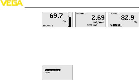
Measured value indica- |
|
The measured value indication shows the digitally indicated value, the |
||||
tion |
|
measurement loop name (measurement loop TAG) and the unit. An |
||||
|
|
|
|
analogue bar graph can also be displayed.If flow measurement with |
||
|
|
|
|
totalizer is activated, an additional indication window with totalizer be- |
||
|
|
|
|
comes available. With activated pump control, an additional window |
||
|
|
|
|
for indication of the assigned pumps is available. By pushing the [>] |
||
|
|
|
|
key you can move between the different indication options. |
||
|
|
|
|
|
|
|
18 |
|
|
|
|
VEGAMET 391 • 4 … 20 mA/HART |
|
130701-EN-36032
36032-EN-130701
6 Setup with the integrated display and adjustment unit
→[OK], you move from the measured value indication into the main menu. Here, you have the choice between the setup assistant for the most important settings and the complete classic menu.
Main menu/Setup as- At the beginning of every setup or parameter adjustment, you have sistant the choice of continuing with the setup assistant or the classic menu
guidance. We recommend using the setup assistant for the initial setup. If later on individual settings should be corrected or added, the most expedient way to do this is via the classic menus.
|
→ |
Select the menu item "Setup assistant" with [->] and confirm with |
|
|
|
[OK]. |
|
Setup assistant |
The setup assistant leads you step-by-step through the standard set- |
||
|
tings. The following steps are carried out: |
|
|
|
• |
Device-TAG (individually adjustable instrument name) |
|
|
• |
designation)Measurement loop TAG (individually adjustable measurement loop |
|
|
• |
Type of input (4 … 20 mA or HART) |
|
|
• |
Measured variable (for example level or process pressure) |
|
|
• |
Adjustment unit (for example m or bar) |
|
|
• |
Min./Max. adjustment |
|
|
• |
Activation of the fail safe relay |
|
|
• |
Configuration of the relay outputs (e.g.setup of pump control or |
|
|
overfill protection) |
|
|
|
• |
Setting Date/Time with option RS232/Ethernet interface |
|
|
• |
Network settings with option "Ethernet interface" |
|
|
When changing the measurement, the assistant can be called up |
|
|
|
any time. The subsequent steps can also be reached individually via |
||
|
the traditional menu navigation. A description of the individual menu |
||
|
items is available in the traditional menus.In chapter "Application |
|
|
|
examples" you will find further information about setup. |
|
|
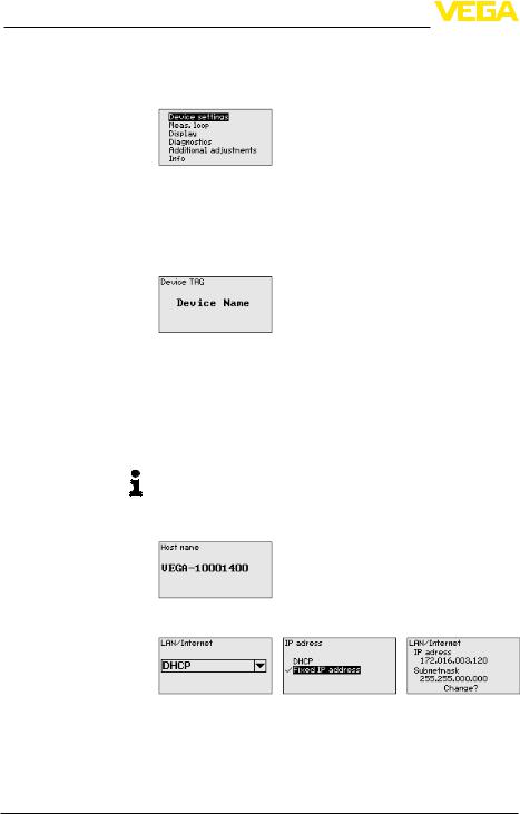
Traditional menu naviga- |
The main menu is divided into six areas with the following functions: |
||
tion/main menu |
• |
Device settings: Includes the device-TAG, settings for network |
|
|
connection such as date/time setting, … |
|
|
|
• |
Measurement loop: Includes settings for input selection, adjust- |
|
|
ment, damping, linearization, scaling, outputs, … |
|
|
|
• |
Display: Includes settings for the displayed measured value, |
|
|
language und brightness of the background lighting |
|
|
|
• |
Diagnosis Includes information on device status, error messages, |
|
|
|
input current, digital inputs |
|
|
|
||
VEGAMET 391 • 4 … 20 mA/HART |
19 |
||
6 Setup with the integrated display and adjustment unit
•Further… settings: Includes simulation, reset, PIN, sensor address,
•Info: Shows serial number, software version, last change, instrument features, MAC addr., …
→Select the requested menu item via the respective keys and confirm with [OK].
Device settings - Device- You can assign an unambiguous name to VEGAMET 391 via the TAG Device-TAG. This function is recommended when several instruments
are implemented and a good documentation of larger systems is required.
→ Carry[OK]. out your settings via the appropriate keys and save with
Device settings - Host For instruments with integrated Ethernet interface, the automatic Name/IP addr. addressing via DHCP is preset, i.e. the IP address must be assigned
by a DHCP server. Generally the instrument is contacted via the Host name. By default, the host name consists of the serial number plus
"VEGA-" in front.As an alternative, it is also possible to enter a static
IP addr. with Subnet mask and optional Gateway addr.
Note:
Keep in mind that your modification will be only effective after a restart ofVEGAMET 391.You can find further information of these network parameters in the supplementary instructions "RS232/Ethernet connection" and in the Online help of the respective DTM.
1.Carry out your settings via the appropriate keys and save with
[OK].
2.Carry out your settings via the appropriate keys and save with
[OK].Disconnect briefly the operating voltage so that the modified settings become effective.
Device settings - Commu- For instruments with integrated RS232 interface, you determine here nication protocol which mode this serial interface should operate in. The following op-
tions are available:
20 |
VEGAMET 391 • 4 … 20 mA/HART |
130701-EN-36032
Loading...