


D84
Table of contents
 Loading...
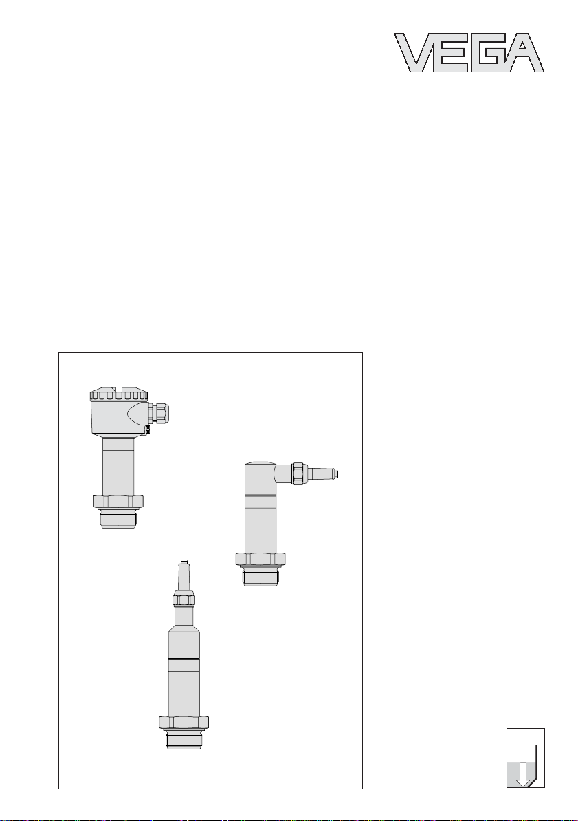
p
Operating Instructions
Hydrostatic pressure
transmitters D84

2 Pressure transmitter D84
Contents
Contents
Safety information ........................................................................ 2
Note Ex area ................................................................................ 2
1 Product description
1.1 Function and configuration .................................................. 4
1.2 Electronics version without adjustment .............................. 5
1.3 Electronics version with integrated adjustment
in connection housing .......................................................... 7
1.4 Electronics for connection to VEGADIS 12 ........................ 8
1.5 Technical data ....................................................................... 9
1.6 Approvals and certificates ................................................ 13
1.7 Dimensions ......................................................................... 14
2 Mounting
2.1 Mounting instructions ......................................................... 18
2.2 Compensation of the atmospheric pressure ................... 18
Safety information
Please read this manual carefully, and also take
note of country-specific installation standards
(e.g. the VDE regulations in Germany) as well
as all prevailing safety regulations and acci-
dent prevention rules.
For safety and warranty reasons, any internal
work on the instruments, apart from that in-
volved in normal installation and electrical con-
nection, must be carried out only by qualified
VEGA personnel.
Note Ex area
Please note the attached safety instructions
containing important information on installation
and operation in Ex areas.
These safety instructions are part of the
operating instructions and come with the Ex
approved instruments.

Pressure transmitter D84 3
3 Electrical connection
3.1 Connection instructions ..................................................... 19
3.2 Terminal assignment .......................................................... 20
3.3 Connection to external connection housing
VEGABOX 01 ..................................................................... 21
3.4 Connection examples ........................................................ 22
4 Setup
4.1 Adjustment structure ......................................................... 23
4.2 Sensor without adjustment ................................................ 24
4.3 Sensor with adjustment insert, adjustment
in the sensor ....................................................................... 24
4.4 Setup with HART
®
handheld ............................................. 26
5.5 Adjustment with PC directly on the sensor ...................... 32
6 Diagnostics............................................................................... 40
7 Instrument modification
7.1 Retrofitting the adjustment insert ...................................... 41
7.2 Exchange of hygienic form seal on D84 .......................... 41
Contents

4 Pressure transmitter D84
Product description
1 Product description
1.1 Function and configuration
The pressure transmitter D84 is an efficient
instrument for hydrostatic level measurement.
A dry ceramic-capacitive CERTEC
®
measuring cell is used as pressure sensor
element.
Pressure transmitter D84
Measuring cell: dry, ceramic-capacitive
Diaphragm: flush, ceramic
Series: flanged version
Standard application: All kind of level
measurements, best suited for food
processing and pharmaceutical industries.
The pressure effects a capacitance change
on the measuring cell. This capacitance
change is detected by an ASIC (Application
Specific Integrated Circuit) and converted
into a pressure-proportional signal by the
integrated electronic module with
microcontroller. Precise, high-resolution digi-
tal processing of measurement data ensures
excellent technical data.
To improve reliability, the functionality of im-
portant electronic components is continu-
ously checked, and internal parameters such
as sensor value, temperature and operating
voltage are closely monitored.
Output signal
The output signal is transferred as a digital or
analogue signal from the pressure transmitter
to the signal conditioning instrument:
• analogue output signal
- unstandardised (in conjunction with
VEGA signal conditioning instrument)
- 4 … 20 mA standardised
• digital output signal (VBUS) for connection
to a digital VEGA signal conditioning instru-
ment (VEGAMET 514V, 515V or VEGALOG
571)
Pressure transmitter D84 5
Product description
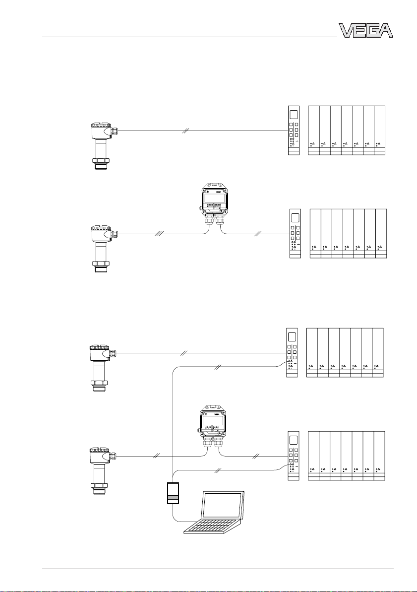
1.2 Electronics version without adjustment
Electronics version B:
Pressure transmitter for connection to VEGA signal conditioning instruments (digital
transmission VBUS)
Electronics version A:
Pressure transmitter for connection to VEGA signal conditioning instruments
Zum Anschluss an
Druckmessumformer mit
analogem Ausgangssignal
VEGABOX 01
TRANSMITTER
-
+
+
-
For connection to
pressure transmitters with
analog output
1
23
10
11 12
Zum Anschluss an
Druckmessumformer mit
analogem Ausgangssignal
VEGABOX 01
TRANSMITTER
-
+
+
-
For connection to
pressure transmitters with
analog output
1
23
10
11 12
e.g. IP 66
e.g. IP 67
VEGABOX 01
VEGALOG
VEGALOG
VEGAMET
VEGAMET
VEGABOX 01
VEGALOG
VEGALOG
VEGAMET
VEGAMET
e.g. IP 66
e.g. IP 67
6 Pressure transmitter D84
Product description
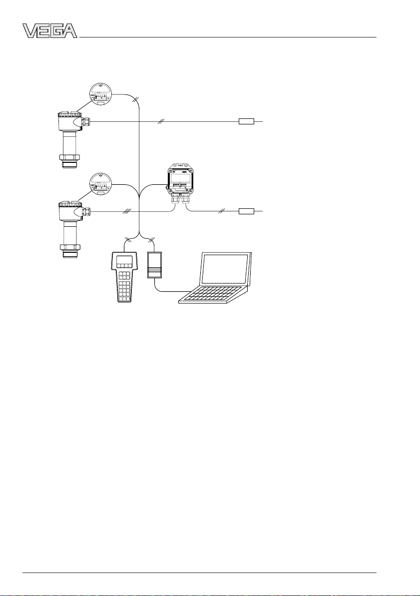
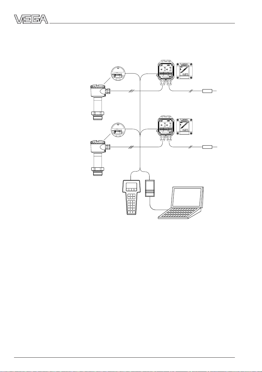
Electronics version I:
Pressure transmitter 4 … 20 mA, HA RT
®
, VVO
VVO
51234
4-20mA
terminal
Klemmeinsatz
+
-
12V...36V DC
4...20mA
51234
4-20mA
terminal
Klemmeinsatz
+
-
12V...36V DC
4...20mA
Zum Anschluss an
Druckmessumformer mit
analogem Ausgangssignal
VEGABOX 01
TRANSMITTER
-
+
+
-
For connection to
pressure transmitters with
analog output
1
23
10
11 12
VEGABOX 01
PLC/DCS
PLC/DCS
e.g. IP 66
e.g. IP 67
HART
®
handheld
250 Ω
250 Ω
Pressure transmitter D84 7
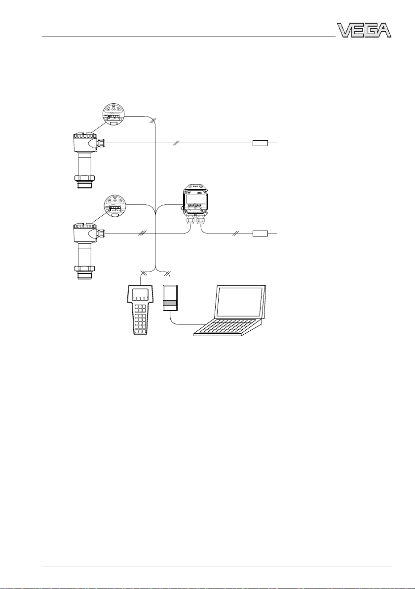
1.3 Electronics version with integrated adjustment in connection housing
Electronics version K:
Pressure transmitter 4 … 20 mA, HART
®
, VVO adjustable
VVO
Zum Anschluss an
Druckmessumformer mit
analogem Ausgangssignal
VEGABOX 01
TRANSMITTER
-
+
+
-
For connection to
pressure transmitters with
analog output
1
23
10
11 12
Bedieneinsatz
operating unit
S
Zt
i
Op
43215
+
-
12V...36V DC
4...20mA
Bedieneinsatz
operating unit
S
Zt
i
Op
43215
+
-
12V...36V DC
4...20mA
VEGABOX 01
PLC/DCS
PLC/DCS
e.g. IP 66
e.g. IP 67
Product description
HART
®
handheld
250 Ω
250 Ω
8 Pressure transmitter D84
1.4 Electronics for connection to VEGADIS 12
VEGADIS 12
DISPLAY
+ -
TRANSMITTER
5876321101112
OPERATE
POINT
DISPLAYTRANSMITTER
END
ZERO
OPERATE
POINT
END
ZERO
VEGADIS 12
DISPLAY
+ -
TRANSMITTER
5876321101112
OPERATE
POINT
DISPLAYTRANSMITTER
END
ZERO
OPERATE
POINT
END
ZERO
51234
VEGADIS 12
Zum Anschluß an
For connection to
+
-
12V...36V DC
terminal
Klemmeinsatz
51234
VEGADIS 12
Zum Anschluß an
For connection to
+
-
12V...36V DC
terminal
Klemmeinsatz
VEGADIS 12
PLC/
DCS
PLC/
DCS
VEGADIS 12
VVO
e.g. IP 66
e.g. IP 67
Product description
HART
®
handheld
250 Ω
250 Ω
Electronics version L:
Pressure transmitter 4 … 20 mA, HA RT
®
, VVO
Pressure transmitter D84 9
Product description
1.5 Technical data
Mechanical data
Materials, wetted parts
Process connection stainless steel 1.4435 or 1.4571
Diaphragm saphire-ceramic
®
Materials, non-wetted parts
Housing Alu (seawater resistant) Pe-powder coated,
stainless steel 1.4571
External connection housing high resistance plastic PBT (Polyester)
Ground terminal stainless steel 1.4305
Window of the display module safety glass
Nominal measuring range Gauge pr. resistance Low pr. re sistance
Gauge pressure
0…0.1 bar / 0…10 kPa 15 bar / 1 500 kPa -0.2 bar / -20 kPa
0…0.2 bar / 0…20 kPa 20 bar / 2 000 kPa -0.4 bar / -40 kPa
0…0.4 bar / 0…40 kPa 30 bar / 3 000 kPa -0.8 bar / -80 kPa
0…1.0 bar / 0…100 kPa 35 bar / 3 500 kPa -1.0 bar / -100 kPa
0…2.5 bar / 0…250 kPa 50 bar / 5 000 kPa -1.0 bar / -100 kPa
0…5.0 bar / 0…500 kPa 65 bar / 6 500 kPa -1.0 bar / -100 kPa
0…10.0 bar / 0…1 000 kPa 90 bar / 9 000 kPa -1.0 bar / -100 kPa
0…20.0 bar / 0…2 000 kPa 130 bar / 13 000 kPa -1.0 bar / -100 kPa
0…40.0 bar / 0…4 000 kPa 200 bar / 20 000 kPa -1.0 bar / -100 kPa
0…60.0 bar / 0…6 000 kPa 300 bar / 30 000 kPa -1.0 bar / -100 kPa
-0.05…+0.05 bar / -5…+5 kPa 15 bar / 1 500 kPa -0.2 bar / -20 kPa
-0.1…+0.1 bar / -10…+10 kPa 20 bar / 2 000 kPa -0.4 bar / -40 kPa
-0.2…+0.2 bar / -20…+20 kPa 30 bar / 3 000 kPa -0.8 bar / -80 kPa
-0.5…+0.5 bar / -50…+50 kPa 35 bar / 3 500 kPa -1.0 bar / -100 kPa
-1.0…0.0 bar / -100…0 kPa 35 bar / 3 500 kPa -1.0 bar / -100 kPa
-1.0…+1.5 bar / -100…+150 kPa 50 bar /5 000 kPa -1.0 bar / -100 kPa
-1.0…+4.0 bar / -100…+400 kPa 65 bar / 6 500 kPa -1.0 bar / -100 kPa
-1.0…+10.0 bar / -100…+1 000 k Pa 90 bar / 9 000 kPa -1.0 b ar / -100 k Pa
-1.0…+20.0 bar / -100…+2 000 kPa 130 bar / 13 000 kPa -1.0 bar / -100 kPa
-1.0 …+40.0 bar / -100…+4 000 kPa 200 bar / 20 000 kPa -1.0 bar / -100 kPa
-1.0…+60.0 bar / -100…+6 000 kPa 300 bar / 30 000 kPa -1.0 bar / -100 kPa
Absolute pressure
0…1.0 bar / 0…100 kPa 35 bar / 3 500 kPa
0…2.5 bar / 0…250 kPa 50 bar / 5 000 kPa
0…5.0 bar / 0 …500 kPa 65 bar / 6 500 kPa
0…10.0 bar / 0…1 000 kPa 90 bar / 9 000 kPa
0…20.0 bar / 0…2 000 kPa 130 bar / 13 000 kPa
0…40.0 bar / 0…4 000 kPa 200 bar / 20 000 kPa
0…60.0 bar / 0…6 000 kPa 300 bar / 30 000 kPa
10 Pressure transmitter D84
Weights
Basic weight without housing approx. 1.6 kg
External housing approx. 400 g
Adjustment and display elements
Pressure transmitter
- terminal insert without adjustment elements
- adjustment insert 2 keys, 1 rotary switch
Electrical data
Adjustment ranges
Zero adjustable from -20 … +95 % of nominal range
Span adjustable from 3.3 … 120 % of nominal range
Supply and signal circuit (analogue transmission, 4 … 20 mA),
electronics version A, C, I and K
Supply voltage 12 … 36 V DC
permissible residual ripple U
SS
≤ 1 V
- at 100 Hz … 10 kHz U
SS
≤ 10 mV
Output signal
- terminal insert - analogue transmission (not standardised)
- 4 … 20 mA
- adjustment insert 4 … 20 mA (adjustable)
Current limitation approx. 22 mA
Fault signal 22 mA (3.6 mA)
Integration time 0 … 10 s
Rise time 70 ms (ti = 0 sec; 0 … 63 %)
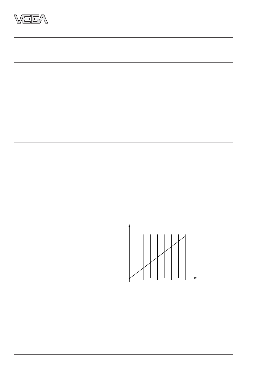
Max. permissible load see load diagram:
Product description
Load in Ω
12
300
600
900
18 24 30 36
Supply voltage
in V
Pressure transmitter D84 11
Product description
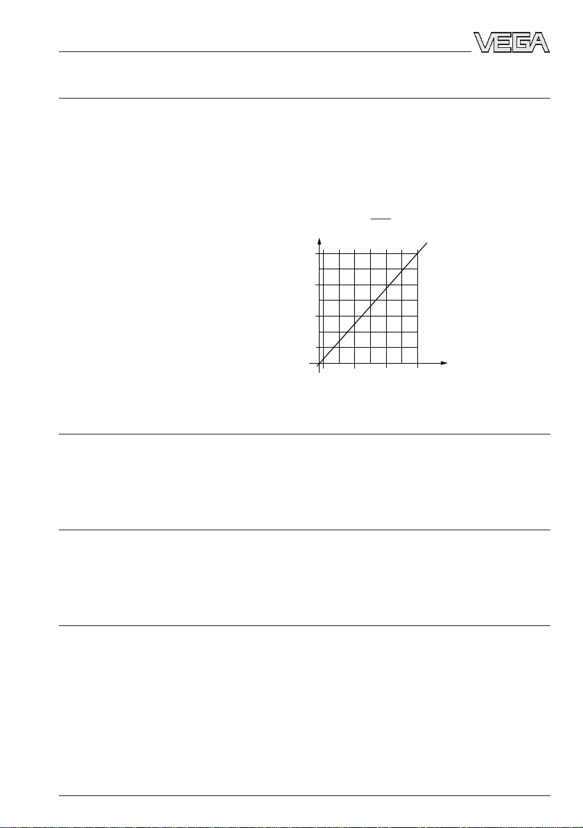
Supply and signal circuit (analogue transmission, 4 … 20 mA),
additional data for electronics version L
Supply voltage for pressure transmitters
in conjunction with VEGADIS 12
- without display 12 … 36 V DC
- with display 17 … 36 V DC
Max. input current 150 mA
Current signal range 3.5 … 22 mA
Max. permissible load see load diagram:
Load diagram with display
300
500
700
18
24 30 36
100
Load in Ω
Supply voltage
in V
Supply and signal circuit on VEGA signal conditioning instruments (digital signal
transmission VBUS), additional data for electronics version B
Supply voltage 25 … 36 V DC, from VEGAMET (VBUS) or
from VEGALOG 571 with EV input card
Data transmission digital (VBUS)
Connection cable 2-wire screened
Cable length max. 1000 m
Integrated overvoltage protection (option)
Nominal response DC voltage
- protective diode 40 V
- gas separator 650 V
Nominal leakage current
- gas separator 20 kA
Connection cables
Cable entry
- housing 2 x M20x1.5 (for cable ø 5…9mm or 9…12mm)
- external connection housing 2 x M20x1.5 (for cable ø 5…9mm or 9…12mm)
Screw terminals
- sensor for wire cross-sections of up to 2.5 mm
2
- external connection housing for wire cross-sections of up to 2.5 mm
2

12 Pressure transmitter D84
Protective measures
1)
Protection IP 66, IP 67, IP 68
VEGABOX 01 IP 66 and IP 67
Protection class III
Overvoltage category III
Accuracy (similar to DIN 16 086, DIN V 19 259 - 1 and IEC 770)
Deviation
Reference conditions (acc. to IEC 770)
- temperature 15°C … 30°C
- humidity 45 % … 75 %
- air pressure 86 kPa … 106 kPa
Determination of characteristics limit point adjustment acc. to DIN 16 086
Characteristics linear
Deviation in characteristics incl. hysteresis and repeatability
- Turn Down 1 : 1 < 0.25 % with accuracy class 0.25
< 0.1 % with accuracy class 0.1
- Turn Down up to 1 : 5 typ. < 0.3 % with accuracy class 0.25
typ. < 0.1 % with accuracy class 0.1
- Turn Down up to 1 : 10 typ. < 0.4 % with accuracy class 0.25
typ. < 0.2 % with accuracy class 0.1
Influence of the ambient temperature
Average temperature coefficient
of the zero signal
2)
- Turn Down 1 : 1 < 0.15 %/10 K with accuracy class 0.25
< 0.05 %/10 K with accuracy class 0.1
- Turn Down up to 1 : 5 typ. < 0.225 %/10 K with accuracy class 0.25
typ. < 0.075 %/10 K with accuracy class 0.1
- Turn Down up to 1 : 10 typ. < 0.3 %/10 K with accuracy class 0.25
typ. < 0.1 %/10 K with accuracy class 0.1
Long-term stability
Long-term stability of the zero signal
3)
< 0.1 % per 2 years
Other actuating variables
Calibration position upright, diaphragm points downwards
Influence of the installation position < 0.2 mbar/20 Pa
Vibration resistance mechanical vibrations with 4 g and
5 … 100 Hz, tested acc. to the regulations of
German Lloyd GL-characteristics 2
Product description
1)
Maintaining the housing protection IP 66 or IP 67 requires the use of a seal that correctly fits the cable in
the cable entry. If the supplied seal does not fit, a suitable seal must be provided by the customer.
2)
In compensated temperature range of 0°C … +80°C, reference temperature 20°C.
3)
Acc. to IEC 770, item 6.3.2 relating to the nominal range.

Pressure transmitter D84 13
Product description
Operating conditions
Ambient conditions
Ambient temperature -40°C … +85°C
- with indicating module -10°C … +60°C
Storage and transport temperature -50°C … +100°C
Product temperature
- Viton seal -20°C … +100°C
- EPDM seal -40°C … +100°C
- Kalrez seal 0°C … +100°C
1.6 Approvals and certificates
Approvals
- Ex Zone 2
- CENELEC EEx ia IIC
- ATEX II 1G EEx ia IIC
If the use of approved instruments is required for certain applications, the appropriate
official documents (test reports, test certificates and conformity certificates) must be ob-
served. These are supplied with the respective instrument.
CE conformity
D84 pressure transmitters meet the requirements of EMC (89/336/EWG) and NSR
(73/23/EWG). Conformity has been judged acc. to the following standards:
EMC Emission EN 50 081 - 1: 1992
Susceptibility EN 50 082 - 2: 1995
NSR EN 61 010: 1993
NAMUR regulations
Full compliance with the NAMUR regulations NE21 and NE 43.
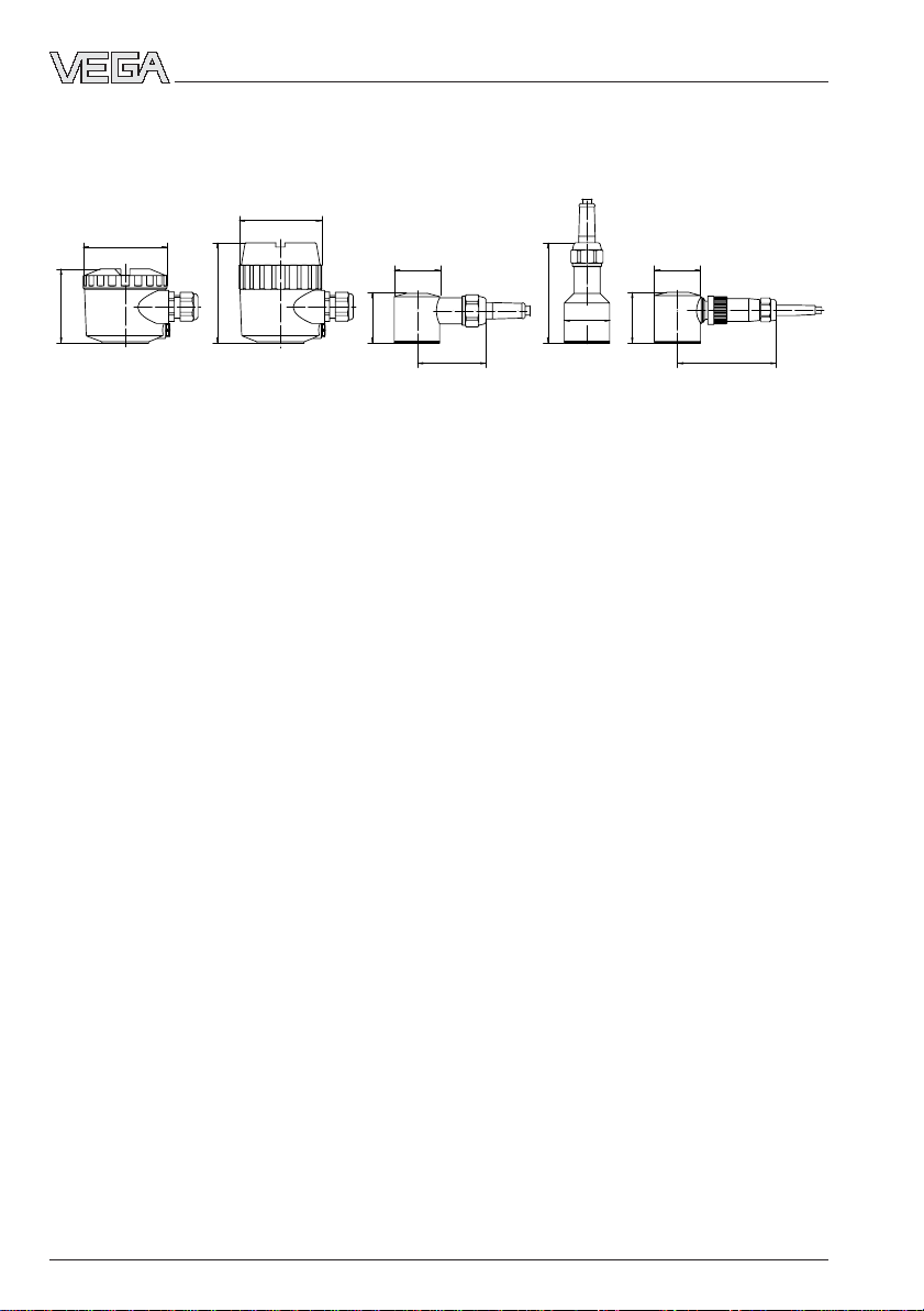
14 Pressure transmitter D84
1.7 Dimensions
Housings
Product description
ø 76
67
ø 75
91
ø 41,6
46
63
ø 41,6
93
ø 41,6
46
90
Loading...