


Operating Instructions
VEGAPULS 54K enamel

Contents
Contents
|
Sicherheitshinweise ..................................................................... |
3 |
|
|
Safety information ........................................................................ |
3 |
|
|
Note Ex area ................................................................................ |
3 |
|
1 |
Product description .................................................................. |
4 |
|
|
1.1 |
Function ................................................................................. |
4 |
|
1.2 |
Application features ............................................................. |
6 |
|
1.3 |
Adjustment ............................................................................ |
6 |
|
1.4 |
Antennas ............................................................................... |
8 |
2 |
Mounting and installation ....................................................... |
9 |
|
|
2.1 |
General installation instructions .......................................... |
9 |
|
2.2 |
Measurement of liquids ..................................................... |
10 |
|
2.3 |
False echoes ...................................................................... |
11 |
|
2.4 |
Common installation mistakes ........................................... |
13 |
3 |
Electrical connection .............................................................. |
15 |
|
|
3.1 |
Connection and connection cable .................................... |
15 |
|
3.2 |
Connecting the sensor ...................................................... |
16 |
|
3.3 |
Connecting the external indicating instrument |
|
|
|
VEGADIS 50 ....................................................................... |
19 |
|
3.4 |
Configuration of measuring systems ............................... |
20 |
4 |
Set-up ........................................................................................ |
28 |
|
|
4.1 |
Adjustment media .............................................................. |
28 |
|
4.2 |
Adjustment with PC ............................................................ |
28 |
|
4.3 |
Adjustment with adjustment module MINICOM ............... |
30 |
|
4.4 |
Adjustment with HART® handheld ................................... |
36 |
5 |
Diagnostics ............................................................................... |
38 |
|
|
5.1 |
Simulation ............................................................................ |
38 |
|
5.2 |
Error codes ........................................................................ |
38 |
041227-EN-101 24
2 |
VEGAPULS 54K enamel |

Sicherheitshinweise
6 Technical data .......................................................................... |
39 |
||
6.1 |
Technical data ..................................................................... |
39 |
|
6.2 |
Approvals ........................................................................... |
43 |
|
6.3 |
Dimensions ......................................................................... |
44 |
|
Supplement ..................................................................................... |
|
46 |
|
Safety Manual |
................................................................................. |
46 |
|
1 |
General ............................................................................... |
46 |
|
|
1.1 |
Validity ................................................................................. |
46 |
|
1.2 |
Area of application ............................................................... |
46 |
|
1.3 |
Relevant standards ............................................................. |
46 |
|
1.4 |
Determination of safety-related characteristics .................. |
47 |
2 |
Planning .............................................................................. |
48 |
|
|
2.1 |
Low demand mode ............................................................... |
48 |
|
2.2 |
High demand or continuous mode ....................................... |
48 |
|
2.3 |
General ................................................................................ |
48 |
3 |
Set-up |
................................................................................. |
49 |
|
3.1 |
Mounting and installation ..................................................... |
49 |
|
3.2 |
Adjustment instructions and parameter settings ................ |
49 |
|
3.3 |
Configuration of the processing unit ................................... |
49 |
4 |
Reaction during operation and in case of failure ............. |
50 |
|
5 |
Recurring function test ....................................................... |
50 |
|
6 |
Safety-related characteristics ........................................... |
51 |
|
SIL declaration of conformity .................................................... |
52 |
||
CE declaration of conformity ..................................................... |
53 |
||
24 101-EN-041227
Safety information
Please read this manual carefully, and also take note of country-specific installation standards (e.g. the VDE regulations in Germany) as well as all prevailing safety regulations and accident prevention rules.
For safety and warranty reasons, any internal work on the instruments, apart from that involved in normal installation and electrical connection, must be carried out only by VEGA personnel.
 Note Ex area
Please note the attached safety instructions containing important information on installation and operation in Ex areas.
These safety instructions are part of the operating instructions manual and come with the Ex approved instruments.
VEGAPULS 54K enamel |
3 |

Product description
1 Product description
VEGAPULS series 50 sensors are a newly developed generation of extremely compact, small radar sensors.
Due to their small housing dimensions and process fittings, the compact sensors are an unobstrusive, and most of all, very costeffective solution for your level measurement applications. With their integrated display and many of the features of the VEGAPULS 81 series, they bring the advantages of radar level measurement to applications where previously, due to high costs, the advantages of non-contact measurement had to be forgone.
The VEGAPULS 54 radar sensor is perfectly suitable for two-wire technology, however, it is also available in four-wire technology where the output signal and power supply are carried on in two separate circuits. The supply voltage and the output signal are transmitted via one two-wire cable. The instruments produce an analogue 4 … 20 mA output signal as output, i.e. measuring signal.
In the enamelled version, the sensors have exceptional chemical resistance, and represent the ideal level sensor technology for corrosive processes.
Radio detecting and ranging: Radar. VEGAPULS radar sensors are used for noncontact, continuous distance measurement. The measured distance corresponds to a filling height and is outputted as level.
1.1 Function
Measuring principle:
emission – reflection – reception
Extremely small 5.8 GHz radar signals are emitted from the antenna of the radar sensor as short pulses. The radar pulses reflected by the sensor environment and the product are received by the antenna as radar echoes. The running period of the radar pulses from emission to reception is proportional to the distance and hence to the level.
Meas. distance
emission - reflection - reception
The radar pulses are emitted by the antenna system as pulse packets with a pulse duration of 1 ns and pulse intervals of 278 ns; this corresponds to a pulse package frequency of 3.6 MHz. In the pulse intervals, the antenna system operates as a receiver. Signal running periods of less than one billionth of a second must be processed and the echo image evaluated in a fraction of a second.
041227-EN-101 24
4 |
VEGAPULS 54K enamel |

Product description
Puls |
1 ns |
278 ns |
Pulse |
break |
Pulse sequence
VEGAPULS can achieve this through a special time transformation procedure which spreads out the more than 3.6 million echo images per second in a slow-motion picture, then freezes and processes them.
t |
t |
Time transformation
Hence, it is possible for the VEGAPULS 50 radar sensors to process the slow-motion pictures of the sensor environment precisely and in detail in cycles of 0.5 to 1 second without using time-consuming frequency analysis (e.g. FMCW, required by other radar techniques).
Nearly all products can be measured
Radar signals display physical properties similar to those of visible light. According to the quantum theory, they propagate through empty space. Hence, they are not dependent on a conductive medium (air), and they spread out like light at the speed of light. Radar signals react to two basic electrical properties:
-the electrical conductivity of a substance
-the dielectric constant of a substance.
All products which are electrically conductive reflect radar signals very well. Even slightly conductive products provide a sufficiently strong reflection for a reliable measurement.
All products with a dielectric constant ε r greater than 2.0 reflect radar pulses sufficiently (note: air has a dielectric constant εr of 1).
% 
|
50 |
|
|
|
|
|
|
|
|
|
|
|
|
|
|
|
|
|
|
|
|
|
|
|
|
|
|
|
|
|
|
|
|
|
|
|
|
||
|
|
|
|
|
|
|
|
|
|
|
|
|
|
|
|
|
|
|
|
|
|
|
|
|
|
|
|
|
|
|
|
|
|
|
|||||
|
|
|
|
|
|
|
|
|
|
|
|
|
|
|
|
|
|
|
|
|
|
|
|
|
|
|
|
|
|
|
|
|
|
|
|
|
|
|
|
|
|
|
|
|
|
|
|
|
|
|
|
|
|
|
|
|
|
|
|
|
|
|
|
|
|
|
|
|
|
|
|
|
|
40 % |
|
||||
|
40 |
|
|
|
|
|
|
|
|
|
|
|
|
|
|
|
|
|
|
|
|
|
|
|
|
|
|
|
|
|
|
|
|
||||||
|
|
|
|
|
|
|
|
|
|
|
|
|
|
|
|
|
|
|
|
|
|
|
|
|
|
|
|
|
|
|
|
|
|
|
|
|
|||
|
|
|
|
|
|
|
|
|
|
|
|
|
|
|
|
|
|
|
|
|
|
|
|
|
|
|
|
|
|
|
|
|
|
|
|||||
|
|
|
|
|
|
|
|
|
|
|
|
|
|
|
|
|
|
|
|
|
|
|
|
|
|
|
|
|
|
|
|
|
|
|
|
|
|
|
|
30 |
|
|
|
|
|
|
|
|
|
|
|
|
|
|
|
|
|
|
|
|
|
|
|
|
|
|
|
|
|
|
|
|
|
|
|
||||
|
|
|
|
|
|
|
|
|
|
|
|
|
|
|
|
25 % |
|
|
|
|
|
|
|
|
|
|
|
|
|
|
|
||||||||
|
|
|
|
|
|
|
|
|
|
|
|
|
|
|
|
|
|
|
|
|
|
|
|
|
|
|
|
|
|
|
|
|
|
|
|
||||
|
|
|
|
|
|
|
|
|
|
|
|
|
|
|
|
|
|
|
|
|
|
|
|
|
|
|
|
|
|
|
|
|
|
|
|
|
|
||
20 |
|
|
|
|
|
|
|
|
|
|
|
|
|
|
|
|
|
|
|
|
|
|
|
|
|
|
|
|
|
|
|
|
|
|
|
||||
|
|
|
|
|
|
|
|
|
|
|
|
|
|
|
|
|
|
|
|
|
|
|
|
|
|
|
|
|
|
|
|
|
|
|
|||||
|
|
|
|
|
|
|
|
|
|
|
|
|
|
|
|
|
|
|
|
|
|
|
|
|
|
|
|
|
|
|
|
|
|
|
|
|
|
|
|
|
10 |
|
|
|
|
5 % |
|
|
|
|
|
|
|
|
|
|
|
|
|
|
|
|
|
|
|
|
|
|
|
|
|
|
|
|
|||||
|
|
|
|
|
|
|
|
|
|
|
|
|
|
|
|
|
|
|
|
|
|
|
|
|
|
|
|
||||||||||||
|
5 |
|
|
|
|
|
|
|
|
|
|
|
|
|
|
|
|
|
|
|
|
|
|
|
|
|
|
|
|
|
|
|
|
|
|
|
|||
|
0 |
|
|
|
|
|
|
|
|
|
|
|
|
|
|
|
|
|
|
|
|
|
|
|
|
|
|
|
|
|
|
|
|
|
|
|
|
|
|
|
|
|
|
|
|
|
|
|
|
2 |
|
|
|
4 |
|
6 |
|
8 |
|
|
|
|
|
|
|
12 |
|
14 |
|
16 |
|
18 |
|
|
|
|
|
|
εr |
|
|
|
|
|
|
0 |
|
|
|
|
|
|
10 |
|
|
|
20 |
|
|
||||||||||||||||||||
|
|
|
|
|
|
|
|
|
|
|
|
|
|
|
|
|
|
|
|
|
|
|
|
|
|
|
|
|
|
|
|
|
|||||||
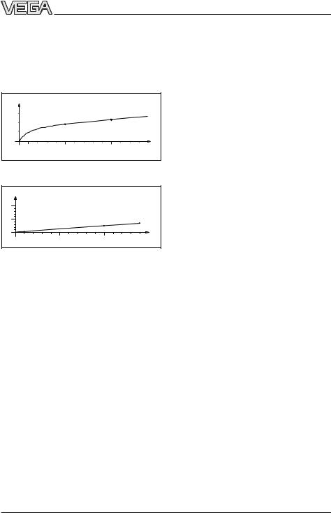
Reflected radar power dependent on the dielectric constant of the measured product
Signal reflectivity grows stronger with increasing conductivity or increasing dielectric constant of the product. Hence, nearly all substances can be measured.
As process fitting, standard flanges of DN 150, DN 200, ANSI 6“ or ANSI 8“ are used. Due to high quality enamel coating, the sensors withstand even extreme chemical and physical conditions. The sensors deliver stable, reproducible analogue or digital level signals with reliability and precision, and have a long useful life.
24 101-EN-041227
VEGAPULS 54K enamel |
5 |
Product description
Continuous and accurate
Unaffected by temperature, pressure and atmosphere content, VEGAPULS radar sensors measure quickly and accurately the levels of widely varying products.
% |
|
|
|
|
|
0,03 |
|
|
0,023 % |
|
|
|
|
|
|
|
|
0,02 |
|
0,018 % |
|
|
|
|
|
|
|
|
|
0,01 |
|
|
|
|
|
0 |
|
|
|
|
|
0 |
100 |
500 |
1000 |
1300 |
˚C |
Temperature influence: Temperature error absolutely zero (e.g. at 500°C 0.018 %)
% |
|
|
|
|
|
|
|
|
|
|
|
|
|
|
10 |
|
|
|
|
|
|
|
|
|
|
|
|
|
|
5 |
|
|
|
|
|
|
|
|
|
2,8 % |
|
|
|
3,89 % |
|
|
|
|
|
|
|
|
|
|
|
|
|
||
|
|
|
|
|
1,44 % |
|
|
|
|
|
|
|
||
|
0,29 % |
|
|
|
|
|
|
|
|
|
|
|||
0 |
|
|
|
|
|
|
|
|
|
|
|
|
||
10 |
20 |
30 |
40 |
|
60 |
70 |
80 |
90 |
|
110 |
120 |
130 |
140 bar |
|
0 |
50 |
100 |
||||||||||||
Pressure influence: Error with pressure increase very low (e.g. at 50 bar 1.44 %)
Rugged and abrasionproof
•non-contact
•high-resistance materials
Exact and reliable
•meas. resolution 1 mm
•unaffected by noise, vapours, dusts, gas compositions and inert gas stratification
•unaffected by varying density and temperature of the medium
•measurement in pressures of -1 … 16 bar and product temperatures of
-40°C … 200°C
Communicative
•integrated measured value display
•optional display module separate from sensor
•connection to all BUS systems: Interbus S, Modbus, Siemens 3964R, Profibus DP, Profibus FMS, ASCII
•adjustment from the PLC level with the PC
•adjustment with HART® handheld
•adjustment with detachable adjustment module, pluggable in the sensor or in the external display
VEGAPULS 50 sensors allow radar level measurement in plants where they were it was hitherto unthinkable because of high costs.
1.2 Application features
Applications
•level measurement of any liquid, limited use in solids
•measurement also in vacuum
•all slightly conductive materials and all substances with a dielectric constant > 2.0 can be measured
•measuring range 0 … 20 m
Two-wire technology
•power supply and output signal on one two-wire cable (Loop powered)
•4 … 20 mA output signal
Approvals
•CENELEC, ATEX, PTB, FM, CSA, ABS, LRS, GL, LR, FCC
1.3 Adjustment
Every measurement set-up is unique. For that reason, every radar sensor needs some basic information on the application and the environment, e.g. which level means "empty“ and which level "full“. Beside this "empty and full adjustment“, many other settings and adjustments are possible with VEGAPULS radar sensors.
The adjustment and parameter setting of radar sensors is carried out with
-the PC
-the detachable adjustment module MINICOM
-the HART® handheld
6 |
VEGAPULS 54K enamel |
041227-EN-101 24
Product description
Adjustment with the PC
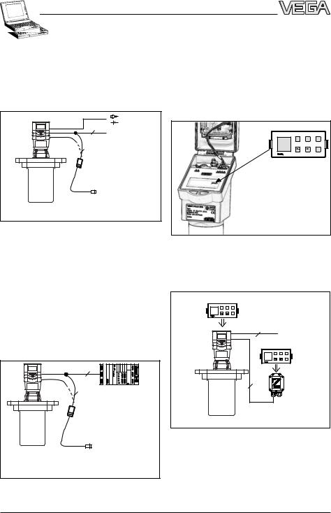
The set-up and adjustment of the radar sensors is generally done on the PC with the adjustment software PACTwareTM. The program leads quickly through the adjustment and parameter setting by means of pictures, graphics and process visualisations.
Adjustment with the adjustment module MINICOM
With the small (3.2 cm x 6.7 cm) 6-key adjustment module with display, the adjustment can be carried out in clear text dialogue. The adjustment module can be plugged into the radar sensor or into the optional, external indicating instrument.
24 101-EN-041227
2
4 ...20 mA
2
Adjustment with the PC on the analogue 4 … 20 mA signal and supply cable or directly on the sensor (four-wire sensor)
The PC can be connected at any measuring site in the system or directly to the signal cable. It is connected by means of the twowire PC interface converter VEGACONNECT 3 to the sensor or the signal cable. The adjustment and parameter data can be saved with the adjustment software on the PC and can be protected by passwords. On request, the adjustments can be quickly transferred to other sensors.
2 |
2 PLC
Adjustment with the PC on the 4 … 20 mA signal and supply cable to the PLC or directly on the sensor (figure: a two-wire sensor)
Tank 1 - + ESC
m (d)
12.345 
 OK
OK
Detachable adjustment module MINICOM
Unauthorised sensor adjustments can be prevented by removing the adjustment module.
Tank 1 |
- |
+ |
m (d) |
|
|
12.345 |
|
OK |
2 |
4 ... 20 mA |
|
|
Tank 1 |
- + |
m (d) |
|
12.345 |
OK |
4
Adjustment with detachable adjustment module. The adjustment module can be plugged into the radar sensor or into the external indicating instrument VEGADIS 50.
VEGAPULS 54K enamel |
7 |
Product description
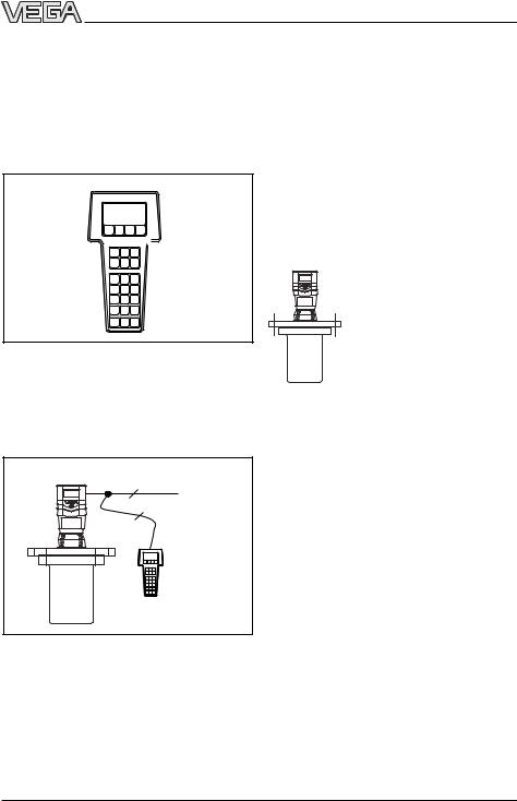
Adjustment with the HART® handheld
Series 50 sensors with 4 … 20 mA output signal can also be adjusted with the HART® handheld. A special DDD (Data Device Description) is not necessary - the sensors can be adjusted with the HART® standard menus of the handheld.
HART Communicator 

HART® handheld
To make adjustments, simply connect the HART® handheld to the 4 … 20 mA output signal cable or insert the two communication cables of the HART® handheld into the adjustment jacks on the sensor.
1.4 Antennas
The antenna is the eye of the radar sensor. The shape of the antenna, however, doesn’t give a casual observer the slightest clue on how carefully the antenna geometry must be adapted to the physical properties of electromagnetic waves. The geometrical form determines focal properties and sensitivity - the same way it determines the sensitivity of a unidirectional microphone.
Horn antennas
The horn antenna is the classical radar antenna in level measurement. The antenna focuses the radar signals very well. Fabricated of 1.4571 (stainless steel) with enamel coating or Hastelloy C22, the antenna is physicaly resistant, and is well suited for pressures up to 16 bar at product temperatures up to 200°C.
2
4 ...20 mA
2
HART® handheld on the 4 … 20 mA signal cable
041227-EN-101 24
8 |
VEGAPULS 54K enamel |

Mounting and installation
2 Mounting and installation
2.1 General installation instructions
Measuring range
The reference plane for the measuring range of the sensor is the enamelled sensor seal shoulder, against which the enamelled vessel seal is placed. The measuring range is
0 … 20 m. For measurements in surge or bypass tubes (pipe antenna) the max. measuring distance decreases by approx. 0.5 m.
Keep in mind that in measuring environments where the medium can reach the sensor flange, buildup may form on the antenna and later cause measurement errors.
False echoes
Flat obstructions and struts cause strong false echoes. They reflect the radar signal with high energy density.
Interfering surfaces with rounded profiles scatter the radar signals into the surrounding space more diffusely and thus generate false echoes with a lower energy density. Hence, those reflections are less critical than those from a flat surface.
full |
empty |
Reference plane |
|
max. filling |
|
|
Measuring range |
max. meas. distance 20 m |
|
Measuring range (operating range) and max. measuring distance
Note: Use of the sensors for applications with solids is limited.
Profiles with flat interfering surfaces cause large false signals
If flat obstructions in the range of the radar signals cannot be avoided, we recommend diverting the interfering signals with a deflector. The deflector prevents the interfering signals from being directly received by the radar sensor. The signals are then so lowenergy and diffuse that they can be filtered out by the sensor.
Round profiles diffuse radar signals
24 101-EN-041227
VEGAPULS 54K enamel
Cover flat interfering surfaces with deflectors
9
Mounting and installation
Emission cone and false echoes
The radar signals are focused by the antenna system. The signals leave the antenna in a conical path similar to the beam pattern of a spotlight. This emission cone depends on the antenna used.
Any object in this beam cone will reflect the radar signals. Within the first few meters of the beam cone, tubes, struts or other installations can interfere with the measurement. At a distance of 6 m, the false echo of a strut has an amplitude nine times greater than at a distance of 18 m.
At greater distances, the energy of the radar signal distributes itself over a larger area, thus causing weaker echoes from obstructing surfaces. The interfering signals are therefore less critical than those at close range.
If possible, orient the sensor axis perpendicularly to the product surface and avoid vessel installations (e.g. pipes and struts) within the 100% emission cone.
If possible, provide a "clear view“ to the product inside the emission cone and avoid vessel installations in the first third of the emission cone.
Optimum measuring conditions exist when the emission cone reaches the measured product perpendicularly and when the emission cone is free from obstructions.
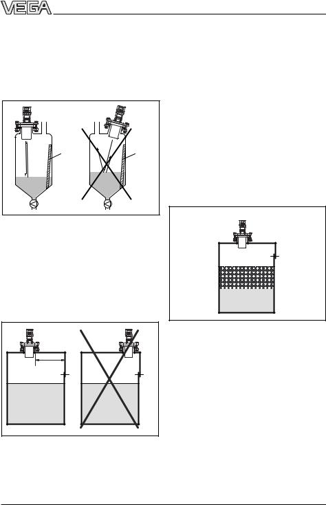
2.2 Measurement of liquids
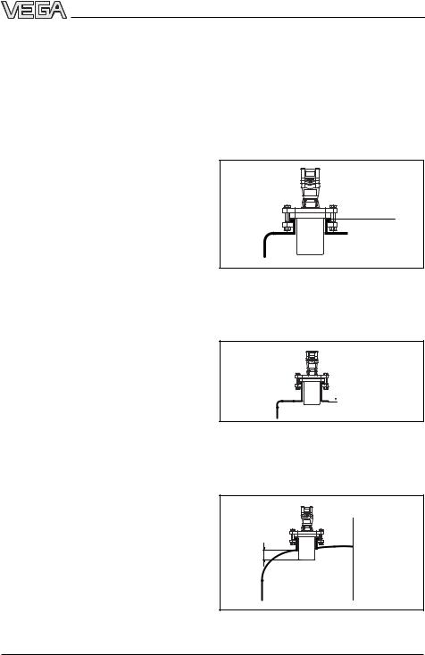
Horn antenna on DIN socket piece
Radar sensors are usually mounted on short DIN socket pieces. The lower side of the instrument flange is the reference plane for the measuring range. The antenna must always protrude out of the flange pipe.
Reference plane
Mounting on DIN socket piece
If the DIN socket piece is longer, please make sure that the horn antenna protrudes at least 10 mm out of the socket.
 > 10 mm
Mounting on longer DIN socket pieces
When mounting on dished or rounded vessel tops, the antenna must also protrude at least 10 mm (longer side of socket).
> 10 mm
Mounting on round vessel tops
10 |
VEGAPULS 54K enamel |
041227-EN-101 24
24 101-EN-041227
Mounting and installation |
|
|
|
On dished vessel tops, please do not mount |
2.3 False echoes |
|
|
the instrument in the centre or close to the |
|
|
|
vessel wall, but approx.½ vessel radius from |
The radar sensor must be installed at a loca- |
||
the centre or from the vessel wall. |
|||
tion where no installations or inflowing material |
|||
|
|||
Dished tank tops can act as paraboloidal |
cross the radar pulses. The following exam- |
||
ples and instructions show the most frequent |
|||
reflectors. If the radar sensor is placed in the |
|||
measuring problems and how to avoid them. |
|||
focal point of the parabolic tank top, the radar |
|||
|
|
||
sensor receives amplified false echoes. The |
|
|
|
radar sensor should be mounted outside the |
Vessel protrusions |
|
|
focal point. Parabolically amplified echoes are |
|
||
|
|
||
thereby avoided. |
Vessel forms with flat protrusions can make |
||
|
|||
|
measurement very difficult due to their strong |
||
|
false echoes. Baffles mounted above these |
||
|
flat protrusions scatter the false echoes and |
||
|
guarantee a reliable measurement. |
|
|
Reference plane |
|
|
|
|
Correct |
Incorrect |
|
1/2 vessel radius
Mounting on round vessel tops
Horn antenna directly on the vessel top
If the stability of the vessel will allow it (sensor
weight), flat mounting directly on the vessel Vessel protrusions (ledge) top is a good and cost-effective solution. The
top side of the vessel is the reference plane.
Intake pipes, i.e. for the mixing of materials - with a flat surface directed towards the sensor - should be covered with an angled baffle that scatters false echoes.
Reference plane |
Correct |
Incorrect |
|
|
Mounting directly on flat vessel top
Vessel protrusions (intake pipe)
VEGAPULS 54K enamel |
11 |

Mounting and installation
Vessel installations |
Inflowing material |
Vessel installations, such as e.g. ladders, often cause false echoes. Make sure when planning your measuring location that the radar signals have free access to the measured product.
Do not mount the instrument in or above the filling stream. Ensure that you detect the product surface and not the inflowing material.
Correct |
Incorrect |
Correct |
Incorrect |
Ladder |
Ladder |
|
|
Inflowing material
Buildup
Vessel installations
Struts
Struts, like other vessel installations, can cause strong false echoes that are superimposed on the useful echoes. Small baffles effectively prevent a direct reception of false echoes. These false echoes are scattered and diffused in the surrounding space and are then filtered out as "echo noise“ by the measuring electronics.
If the sensor is mounted too close to the vessel wall, product buildup and other deposits on the vessel wall cause false echoes. Position the sensor at a sufficient distance from the vessel wall. Please also note chapter "4.1 General installation instructions“.
Correct |
|
|
|
|
Incorrect |
|||||||||||
|
|
|
|
|
|
|
|
|
|
|
|
|
|
|
|
|
|
|
|
|
|
|
|
|
|
|
|
|
|
|
|
|
|
Correct |
Incorrect |
Shields
Buildup
Struts
041227-EN-101 24
12 |
VEGAPULS 54K enamel |

24 101-EN-041227
Mounting and installation
Strong product movements
Strong turbulence in the vessel, e.g. caused by powerful stirrers or strong chemical reactions, can seriously interfere with the measurement. A surge or bypass tube (see illustration) of sufficient size always enables reliable and problem-free measurement even if strong turbulence occurs in the vessel, provided there is no product buildup in the tube.
Correct |
Incorrect |
> 500 mm
100 % 


75 %
0 %
Strong product movements
Products tending to slight buildup can be detected by using a measuring tube with 150 mm nominal width or more. In a measuring tube of this size, buildup does not cause any problems.
2.4 Common installation mistakes
Socket piece too long
If the sensor is mounted in a socket extension that is too long, strong false echoes are generated which interfere with the measurement. Make sure that the horn antenna protrudes at least 10 mm out of the socket piece.
Correct |
Incorrect |
> 10 mm |
Correct and incorrect socket length
Parabolic effects on dished or arched vessel tops
Round or parabolic tank tops act on the radar signals like a parabolic mirror. If the radar sensor is placed at the focal point of such a parabolic tank top, the sensor receives amplified false echoes. The optimum mounting location is generally in the range of half the vessel radius from the centre.
Correct
< 10 mm 
1/2
radius
Incorrect
Incorrect
Mounting on a vessel with parabolic tank top
VEGAPULS 54K enamel |
13 |
|
|
Mounting and installation |
|
Wrong orientation to the product |
If there are good reflection conditions (liquid |
||
|
|
medium, no vessel installations), we recom- |
|
Weak measuring signals are generated if the |
mend locating the sensor where there is no |
||
vessel wall within the inner emission cone. For |
|||
sensor is not directly pointed at the product |
|||
products in less favourable reflection envi- |
|||
surface. Orient the sensor axis perpendicu- |
|||
ronments, it is a good idea to also keep the |
|||
larly to the product surface to achieve opti- |
|||
outer emission cone free of interfering instal- |
|||
mum measuring results. |
|
||
|
lations. Note chapter "4.1 General installation |
||
|
|
||
|
|
instructions“. |
|
Correct |
Incorrect |
|
|
|
|
Foam generation |
|
|
|
Thick, dense and creamy foam on the prod- |
|
Ladder |
Ladder |
uct can cause incorrect measurements. Take |
|
|
|
measures to avoid foam, measure in a by- |
|
|
|
pass tube or use another measuring technol- |
|
|
|
ogy, e.g. capacitive meas. probes or |
|
|
|
hydrostatic pressure transmitters. |
|
Direct sensor vertically to the product surface
Sensor too close to the vessel wall
If the radar sensor is mounted too close to the vessel wall, strong false echoes can be caused. Buildup, rivets, screws or weld joints superimpose their echoes onto the product i.e. useful echo. Please ensure a sufficient distance from the sensor to the vessel wall.
Foam generation
Sensor too close to the vessel wall
041227-EN-101 24
14 |
VEGAPULS 54K enamel |

24 101-EN-041227
Electrical connection
3 Electrical connection
3.1Connection and connection cable
Safety information
Note!
In Ex applications, grounding on both ends is not allowed due to potential transfer.
As a rule, do all connecting work in the complete absence of line voltage. Always switch off the power supply before you carry out connecting work on the radar sensors. Protect yourself and the instruments, especially when using sensors which do not operate with low voltage.
Qualified personnel
Instruments which are not operated with protective low voltage or DC voltage must only be connected by qualified personnel.
Connection and screening
A standard two or four-wire cable (sensors with separate supply) with max. 2.5 mm2 wire cross-section can be used for connection. Quite often, the "electromagnetic pollution" caused by electronic actuators, energy cables and transmitting stations is so considerable that the sensor cable should be screened.
We recommend the use of screened cable. Screening is also a good preventative measure against future sources of interference. Ground the cable screen preferably on the sensor.
It is a good idea to ground the cable screen on both ends. However, you must make sure that no ground equalisation currents flow through the cable screening. Ground equalisation currents can be avoided by potential equalisation systems. If ground equalisation cables are not available, grounding on both ends can be realised by connecting (e.g. in the switching cabinet) one end via a capacitor1) to the ground potential. Use a very lowresistance ground connection (foundation, plate or mains earth).
Ex protection
If an instrument is used in hazardous areas, the respective regulations, conformity certificates and type approvals for systems in Ex areas must be noted (e.g. DIN 0165).
Intrinsically safe circuits must not be connected with more than one active instrument (i.e. an instrument delivering electrical energy) must not be connected. Please note the special installation regulations (DIN 0165).
Connection cable
Make sure that the connection cables are specified for the expected conditions in your systems. The cable must have an outer diameter between 5 and 9 mm (1/2 to 1/3 inch), or with Ex d housing, 3.1 … 8.7 mm (0.12 to
0.34 inch). Otherwise, the seal effect of the cable entry would not be ensured.
Cables for intrinsically safe circuits must be marked blue and may not be used for other circuits.
Earth conductor terminal
On VEGAPULS 54 sensors, the earth conductor terminal is galvanically connected to the flange.
1)max. 10 nF, e.g. voltage resistance 1500 V, ceramic.
VEGAPULS 54K enamel |
15 |

|
|
Electrical connection |
|
3.2 Connecting the sensor |
Now insert the cable through the cable entry |
||
|
|
into the sensor. Screw the sleeve nut back |
|
After mounting the sensor at the measure- |
onto the cable entry and clamp the stripped |
||
wires of the cable into the proper terminal |
|||
ment location according to the instructions in |
|||
positions. |
|||
chapter "4 Mounting and installation“, loosen |
|||
|
|||
the closing screw on top of the sensor. The |
The terminals hold the wire without a screw. |
||
sensor lid with the optional indication display |
|||
can then be opened. Unscrew the sleeve nut |
Press the white opening levers with a small |
||
screwdriver and insert the copper core of the |
|||
and slip it over the connection cable (after |
|||
connection cable into the terminal opening. |
|||
removing about 10 cm of cable mantle). The |
|||
Check the hold of the individual wires in the |
|||
sleeve nut of the cable entry has a self-lock- |
|||
terminals by lightly pulling on them. |
|||
ing ratchet that prevents it from opening on |
|||
its own. |
|
||
Version with plastic housing
Power supply
4 … 20 mA (passive) 1)
+ |
- |
To the indicating instrument in the |
|
sensor lid or to the external indicating |
|||
|
|
||
|
|
instrument VEGADIS 50 |
Power supply
+ - |
4 … 20 mA (active) 2) |
|
|
|
+ - |
Terminals (max. 2.5 mm2
wire cross-section)
1 2 |
C |
3 4 5 6 7 8 |
1 2 |
C |
3 4 5 6 7 8 |
|
|
1 2 |
C |
5 6 7 8 |
1 2 |
C |
3 4 5 6 7 8 |
|
|
+ - |
Commu- |
|
(+) |
(-) |
Commu- |
+ - |
Opening |
nication |
|
nication |
tabs |
||||
|
Display |
L1 |
N |
4...20 mA Display |
|||
4...20 mA |
|
|
|||||
|
|
|
|
|
|
|
|
Tank 1 |
- |
+ |
ESC |
m (d) |
|
|
|
12.345 |
|
|
OK |
|
|
|
Sockets for connection of the HART® handheld or the VEGACONNECT
Tank 1 |
- |
+ |
ESC |
m (d) |
|
|
|
12.345 |
|
|
OK |
|
|
|
|
Pluggable |
|
|
adjustment |
|
Two-wire technology in |
module |
Four-wire technology in |
MINICOM |
||
plastic housing |
|
plastic housing |
(loop powered) |
|
(separate supply) |
1) 4 … 20 mA passive means that the sensor |
2) 4 … 20 mA active means that the sensor provides |
|
consumes a level-dependent current of |
|
a level-dependent current of 4 … 20 mA (current |
4 … 20 mA (consumer). |
|
source). |
|
|
|
16 |
|
VEGAPULS 54K enamel |
041227-EN-101 24

Electrical connection |
|
|
|
|
|
|
|
|
|
|
|
|
|
||||||
Version with aluminium housing |
|
|
|
|
|
|
|
|
|
|
|||||||||
Two-wire technology |
|
Four-wire technology |
|
|
|
|
|
|
|||||||||||
(loop powered) |
|
|
|
|
|
|
|
|
|
|
4 … 20 mA active 2) |
||||||||
4 … 20 mA passive 1) |
|
|
|
|
|
+ |
|
|
- |
|
|
To the indicating |
|||||||
+ |
|
- |
To the indicating instrument in the |
Voltage supply |
|
|
|
|
|
|
|
instrument in the sensor |
|||||||
|
sensor lid or to the external indicating |
|
|
|
|
|
|
|
lid or to the external |
||||||||||
|
|
|
- |
|
|
|
|
|
|
||||||||||
|
|
|
instrument VEGADIS 50 |
|
+ |
|
|
|
|
|
|
indicating instrument |
|||||||
|
|
|
|
|
|
|
|
|
|
|
|
VEGADIS 50 |
|||||||
|
|
|
|
|
|
|
|
|
|
M20 x 1.5 |
|
|
|
|
|
|
|
|
|
|
|
|
|
|
|
|
|
|
|
|
|
|
|
|
|
|
|
|
|
|
|
|
|
|
|
|
|
|
M20 x 1.5 |
(diameter of |
|
|
|
|
|
|
|
|
|
|
|
|
|
|
|
|
|
|
the connection |
|
|
|
|
|
|
|
|
|
|
|
|
|
|
|
|
|
|
|
(diameter of the |
cable |
|
|
|
|
|
|
|
|
|
|
|
|
|
|
|
|
|
|
connection cable |
6…9 mm) |
|
|
|
|
|
|
|
|
M20 x 1.5 |
|
|
|
|
|
|
|
|
|
5…9 mm) |
|
|
|
|
|
|
|
|
|
|
1 |
2 |
C |
3 |
4 |
5 |
6 |
7 |
8 |
Sockets for connec- |
|
|
|
|
|
|
|
|
|
|
|
|
|
|
|
|
|
|
|
|
|
|
|
|
|
|
|
|
||
1 |
2 |
C |
3 |
4 |
5 |
6 |
7 |
8 |
tion of |
|
1 |
2 |
C |
3 |
4 |
5 |
6 |
7 |
8 |
L1 |
N |
nication 4...20mA |
Display |
VEGACONNECT |
|
|
|
|
|
|
|
|
|
||||||
(+) (-) |
Commu- + - |
|
|
|
|
|
|
|
|
|
|
|
|
|
|
|
|
||
|
|
|
|
|
|
|
|
|
(communication |
1 |
2 |
C |
3 |
4 |
5 |
6 |
7 |
8 |
|
|
|
- |
+ |
|
|
|
|
(+) (-) |
Commu- |
+ - |
|
|
Display |
||||||
|
|
|
ESC |
|
sockets) |
|
L1 |
N |
nication |
4...20mA |
|||||||||
|
|
|
|
|
|
|
|
|
|
|
|
|
|
||||||
|
|
|
|
|
|
OK |
|
|
|
|
|
|
- |
+ |
|
ESC |
|
|
|
|
|
|
|
|
|
|
|
|
|
|
|
|
|
|
|
|
OK |
|
|
1)4 … 20 mA passive means that the sensor consumes a level-dependent current of 4 … 20 mA (consumer).
2)4 … 20 mA active means that the sensor provides a level-dependent current of 4 … 20 mA (current source).
24 101-EN-041227
VEGAPULS 54K enamel |
17 |
 Loading...