


Operating Instructions
External display and adjustment unit for plics® sensors
VEGADIS 81
Document ID: 43814

Contents
Contents
1 About this document |
4 |
|
1.1 |
Function............................................................................................................................ |
|
1.2 |
Target group...................................................................................................................... |
4 |
1.3 |
Symbolism used............................................................................................................... |
4 |
2 For your safety |
5 |
|
2.1 |
Authorised personnel........................................................................................................ |
|
2.2 |
Appropriate use................................................................................................................ |
5 |
2.3 |
Warning about incorrect use............................................................................................. |
5 |
2.4 |
General safety instructions................................................................................................ |
5 |
2.5 |
CE conformity................................................................................................................... |
6 |
2.6 |
NAMUR recommendations............................................................................................... |
6 |
2.7 |
Environmental instructions................................................................................................ |
6 |
3 Product description |
7 |
|
3.1 |
Configuration.................................................................................................................... |
|
3.2 |
Principle of operation........................................................................................................ |
8 |
3.3 |
Packaging, transport and storage..................................................................................... |
9 |
3.4 |
Accessories and replacement parts................................................................................ |
10 |
4 |
Mounting |
11 |
|
|
4.1 |
General instructions........................................................................................................ |
|
|
4.2 |
Mounting instructions...................................................................................................... |
11 |
5 |
Connecting to the sensor |
13 |
|
|
5.1 |
Preparing the connection................................................................................................ |
|
|
5.2 |
Connection procedure.................................................................................................... |
13 |
|
5.3 |
Wiring plan...................................................................................................................... |
15 |
|
5.4 |
Connection examples..................................................................................................... |
17 |
6 |
Set up with the display and adjustment module |
19 |
|
|
6.1 |
Short description............................................................................................................. |
|
|
6.2 |
Insert display and adjustment module............................................................................. |
19 |
|
6.3 |
Adjustment system.......................................................................................................... |
20 |
|
6.4 |
Setup steps..................................................................................................................... |
21 |
7Maintenance and fault rectification
|
7.1 |
Maintenance................................................................................................................... |
22 |
|
7.2 |
Rectify faults................................................................................................................... |
22 |
|
7.3 |
Instrument repair............................................................................................................. |
22 |
8 |
Dismounting |
23 |
|
|
8.1 |
Dismounting steps.......................................................................................................... |
|
|
8.2 |
Disposal.......................................................................................................................... |
23 |
9 |
Supplement |
24 |
|
|
9.1 |
Technical data................................................................................................................. |
|
|
9.2 |
Dimensions..................................................................................................................... |
27 |
2 |
VEGADIS 81 • |
130502-EN-43814

43814-EN-130502
VEGADIS 81 •
Contents
Safety instructions for Ex areas
Please note the Ex-specific safety information for installation and operation in Ex areas. These safety instructions are part of the operating instructions manual and come with the Ex-approved instruments.
Editing status: 2013-04-10
3
1 About this document
1 About this document
1.1Function
This operating instructions manual provides all the information you need for mounting, connection and setup as well as important instructions for maintenance and fault rectification.Please read this information before putting the instrument into operation and keep this manual accessible in the immediate vicinity of the device.
1.2Target group
This operating instructions manual is directed to trained specialist personnel. The contents of this manual should be made available to these personnel and put into practice by them.
1.3Symbolism used
•
→
Information, tip, note
This symbol indicates helpful additional information.
Caution: If this warning is ignored, faults or malfunctions can result.
Warning: If this warning is ignored, injury to persons and/or serious damage to the instrument can result.
Danger: If this warning is ignored, serious injury to persons and/or destruction of the instrument can result.
Ex applications
This symbol indicates special instructions for Ex applications.
List
The dot set in front indicates a list with no implied sequence.
Action
This arrow indicates a single action.
1Sequence
Numbers set in front indicate successive steps in a procedure.
Battery disposal
This symbol indicates special information about the disposal of batteries and accumulators.
130502-EN-43814
4 |
VEGADIS 81 • |

43814-EN-130502
VEGADIS 81 •
2 For your safety
2 For your safety
2.1Authorised personnel
All operations described in this operating instructions manual must be carried out only by trained specialist personnel authorised by the plant operator.
During work on and with the device the required personal protective equipment must always be worn.
2.2Appropriate use
VEGADIS 81 is an external display and adjustment unit for plics® sensors.
You can find detailed information on the application range in chapter
"Product description".
Operational reliability is ensured only if the instrument is properly used according to the specifications in the operating instructions manual as well as possible supplementary instructions.
For safety and warranty reasons, any invasive work on the device beyond that described in the operating instructions manual may be carried out only by personnel authorised by the manufacturer. Arbitrary conversions or modifications are explicitly forbidden.
2.3Warning about incorrect use
Inappropriate or incorrect use of the instrument can give rise to application-specific hazards, e.g.vessel overfill or damage to system components through incorrect mounting or adjustment.
2.4General safety instructions
This is a state-of-the-art instrument complying with all prevailing regulations and guidelines. The instrument must only be operated in a technically flawless and reliable condition.The operator is responsible for the trouble-free operation of the instrument.
During the entire duration of use, the user is obliged to determine the compliance of the necessary occupational safety measures with the current valid rules and regulations and also take note of new regulations.
The safety instructions in this operating instructions manual, the national installation standards as well as the valid safety regulations and accident prevention rules must be observed by the user.
For safety and warranty reasons, any invasive work on the device beyond that described in the operating instructions manual may be carried out only by personnel authorised by the manufacturer. Arbitrary conversions or modifications are explicitly forbidden.
The safety approval markings and safety tips on the device must also be observed.
5

2 For your safety
2.5CE conformity
The device fulfills the legal requirements of the applicable EC guidelines.By affixing the CE marking, we confirm successful testing of the product.
You can find the CE Certificate of Conformity in the download section of our homepage.
2.6NAMUR recommendations
NAMUR is the automation technology user association in the process industry in Germany. The published NAMUR recommendations are accepted as the standard in field instrumentation.
The device fulfills the requirements of the following NAMUR recommendations:
•NE 53 – Compatibility of field devices and display/adjustment components
For further information see www.namur.de.
2.7Environmental instructions
Protection of the environment is one of our most important duties. That is why we have introduced an environment management system with the goal of continuously improving company environmental protection.The environment management system is certified according to DIN EN ISO 14001.
Please help us fulfill this obligation by observing the environmental instructions in this manual:
•
•
Chapter "Packaging, transport and storage" Chapter "Disposal"
130502-EN-43814
6 |
VEGADIS 81 • |
43814-EN-130502
3 Product description
3 Product description
3.1Configuration
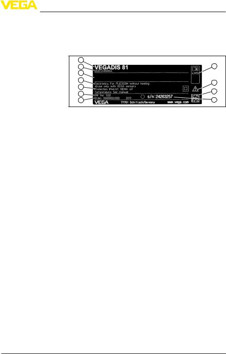
Type plate |
The type label on the housing contains the most important data for |
|
identification and use of the instrument: |
1 |
11 |
2 |
|
3 |
|
4 |
10 |
|
5 |
||
9 |
||
6 |
||
7 |
8 |
Fig. 1: Layout of the type label (example)
1Instrument version
2Product code
3Approval
4Electronics/Voltage supply
5Protection rating
6Hardware version
7Order number
8Serial number of the instrument
9Data-Matrix-Code for Smartphone-App
10Note to observe the instrument documentation
11ID numbers, instrument documentation
Device data |
With the instrument serial number on the type label, you can (depend- |
|
ing on the instrument) gain access e.g. to the following data on our |
|
website: |
•Article number of the instrument (HTML)
•Delivery date (HTML)
•Order-specific instrument features (HTML)
•Operating instructions at the time of shipment (PDF)
Go to www.vega.com, "VEGA Tools" and "Instrument search". Enter the serial number.
As an alternative, you have access to these data via your Smartphone:
•Download the Smartphone-App "VEGA Tools" from the "Apple App Store " or the "Google Play Store"
•Scan the Data-Matrix-Code on the type label of the instrument or
•Enter the serial number manually into the App
Instrument versions |
TheVEGADIS 81 is available in different housing materials, see |
|
chapter "Technical data". |
The instrument is optionally available with or without display and adjustment module.
The display and adjustment module can be optionally equipped with heating to ensure good readability at low temperatures down to -40 °C (-40 °F).
VEGADIS 81 • |
7 |

3 Product description
Scope of delivery |
The scope of delivery encompasses: |
||||||||||
|
• |
Display and adjustment unit VEGADIS 81 |
|||||||||
|
• |
Cable entry M20 x 1 for the sensor |
|||||||||
|
• |
Documentation |
|||||||||
|
–– |
this operating instructions manual |
|||||||||
|
|
|
–– Operating instructions manual 27835 "Display and adjustment |
||||||||
|
|
|
–– |
module PLICSCOM" (optional) |
|||||||
|
|
|
Ex-specific "Safety instructions" (with Ex versions) |
||||||||
|
|
|
–– |
if necessary, further certificates |
|||||||
|
3.2 |
Principle of operation |
|||||||||
Application area |
The VEGADIS 81 is an external measured value indicating unit that |
||||||||||
|
can also be used to adjust the sensors. |
||||||||||
|
Depending on the sensor, it can be mounted up to 25 m or 50 m away |
||||||||||
|
from the sensor and is directly powered by the sensor. A separate |
||||||||||
|
voltage supply is not required. |
||||||||||
|
If the sensor is difficult to access, it can be mounted at a more favour- |
||||||||||
|
able location. |
||||||||||
Application example |
The measured value indication and the sensor adjustment are carried |
||||||||||
|
out via the display and adjustment module integrated in VEGADIS 81. |
||||||||||
|
|
|
|
2 |
|
|
|
|
|
|
|
|
|
|
|
|
|
|
|
|
|
|
|
|
|
|
|
|
|
|
|
|
|
|
|
|
|
|
|
|
|
|
|
|
|
|
|
|
|
|
|
|
|
|
|
|
|
|
|
|
|
|
|
|
|
|
3 |
|
4 |
||
|
|
|
|
|
|
|
|
||||
|
|
|
|
|
|
||||||
|
|
|
|
4 |
|
||||||
|
|
|
|
|
|
|
|||||
|
|
|
|
1 |
|
|
|
|
|
|
|
|
|
|
|
|
|
|
|
|
|
|
|
|
|
|
|
|
|
|
|
|
|
|
|
Application example - with heating
Fig. 2: Connection of VEGADIS 81 to the sensor
1Voltage supply/Signal output sensor
2Sensor
3Connection cable, sensor - VEGADIS 81
4VEGADIS 81
Measured value indication and sensor adjustment are carried out via the display and adjustment module integrated in VEGADIS 81.
Due to the low ambient temperatures, the version with heated display and adjustment module is selected for this example.
130502-EN-43814
8 |
VEGADIS 81 • |

3 Product description
43814-EN-130502
Application example - Adjustment via PC with PACTware
Packaging
2
3
4
4
1 
 5
5
Fig. 3: Connection of VEGADIS 81 to the sensor
1Voltage supply/Signal output sensor
2Sensor
3Connection cable, sensor - VEGADIS 81
4VEGADIS 81 with integrated heating
5Voltage supply, heating
The sensor adjustment is carried out via the VEGADIS 81, the VEGACONNECT as well as a PC with PACTware.
|
2 |
|
|
3 |
|
|
4 |
|
1 |
4 |
|
5 |
||
|
Fig. 4: Connection of VEGADIS 81 to the sensor and the PC
1Voltage supply/Signal output sensor
2Sensor
3Connection cable VEGADIS 81 - Sensor
4VEGADIS 81
5VEGACONNECT
6PC with PACTware
3.3Packaging, transport and storage
Your instrument was protected by packaging during transport. Its capacity to handle normal loads during transport is assured by a test based on ISO 4180.
The packaging of standard instruments consists of environmentfriendly, recyclable cardboard. For special versions, PE foam or PE foil is also used. Dispose of the packaging material via specialised recycling companies.
VEGADIS 81 • |
9 |

3 Product description
Transport |
Transport must be carried out under consideration of the notes on the |
|
transport packaging. Nonobservance of these instructions can cause |
|
damage to the device. |
Transport inspection |
The delivery must be checked for completeness and possible transit |
|
damage immediately at receipt. Ascertained transit damage or con- |
|
cealed defects must be appropriately dealt with. |
Storage
Storage and transport temperature
Display and adjustment module
10
Up to the time of installation, the packages must be left closed and stored according to the orientation and storage markings on the outside.
Unless otherwise indicated, the packages must be stored only under the following conditions:
•Not in the open
•Dry and dust free
•Not exposed to corrosive media
•Protected against solar radiation
•Avoiding mechanical shock and vibration
•Storage and transport temperature see chapter "Supplement - Technical data - Ambient conditions"
•Relative humidity 20 … 85 %
3.4Accessories and replacement parts
The display and adjustment module PLICSCOM is used for measured value indication, adjustment and diagnosis. It can be inserted into the sensor or the external display and adjustment unit and removed at any time.
You can find further information in the operating instructions "Display and adjustment module PLICSCOM" (Document-ID 27835).
130502-EN-43814
VEGADIS 81 •
 Loading...