


 Loading...
Level and Pressure
Operating instructions
VEGABAR 20
+ |
- |
- |
DISPLAY |
4 ¼ 20 mA |
+ |
VEGADIS 10 |
|
|
12 ¼ 36 V DC |
E12 |
|
0 - 20 bar
p

Safety information
Safety information
The described module must only be installed and operated as described in these operating instructions. Please note that other action can cause damage for which VEGA does not take responsibility.
Note Ex-area
Please note the approval documents attached (yellow binder), and especially the safety data sheet included .
2 |
VEGABAR 20 |

Contents
Contents
|
Safety information ........................................................................ |
2 |
|
|
Note Ex-area ................................................................................ |
2 |
|
1 |
Product description |
|
|
|
1.1 |
Function and configuration .................................................. |
4 |
|
1.2 |
Self-monitoring ..................................................................... |
4 |
|
1.3 |
Technical data ....................................................................... |
5 |
|
1.4 |
Approvals ............................................................................. |
9 |
|
1.5 |
Dimensions ......................................................................... |
10 |
2 |
Mounting ................................................................................... |
11 |
|
3 |
Electrical connection |
|
|
|
3.1 |
Connection information ...................................................... |
11 |
|
3.2 |
Connection plan ................................................................. |
12 |
|
3.3 |
Connection examples ........................................................ |
13 |
4 |
Set-up |
|
|
|
4.1 |
Adjustment of the basic functions .................................... |
14 |
|
4.2 |
Menu-guided adjustment with additional functions ......... |
15 |
|
4.3 |
Indicating module ............................................................... |
20 |
5 |
Diagnosis |
|
|
|
5.1 |
Maintenance ....................................................................... |
21 |
|
5.2 |
Failure removal ................................................................... |
21 |
6 |
Instrument modification |
|
|
|
6.1 |
Interchanging adjustment modules .................................. |
23 |
VEGABAR 20 |
3 |

Product description
1 Product description
1.1 Function and configuration
The VEGABAR 20 process pressure transmitters are efficient instruments for process pressure measurement. The dry ceramiccapacitive measuring cell CERTEC® is used as a pressure sensor element. The process pressure causes a capacitance change within the measuring cell via the diaphragm. This capacitance change is detected by an ASIC (application specific integrated circuit) and converted into a pressure proportional signal by an integrated oscillator with microcomputer. Precise digital processing of measured data with highest resolution ensures excellent technical data.
The oscillator is powered by a separate VEGA-signal conditioning instrument, a stabilised power supply unit or a PLC (active input). After adjustment, a standardised current signal of 4 … 20 mA is available which can be displayed (e.g. in PLC-sys- tems) or further processed.
Four versions are available for adjustment:
-adjustment module directly on VEGABAR
-adjustment module in external housing (VEGADIS 10)
-via PC with adjustment software (see manual "VEGA Visual Operating (VVO)“)
-in the control room on the signal conditioning instrument
1.2 Self-monitoring
Important electronic components are checked for their function, while internal parameters, such as sensor value, temperature and operating voltage, are monitored to increase reliability.
VEGABAR 20 with the ceramic CERTEC®- measuring cell offers the advantage of continuous self-monitoring. The measuring and reference capacitances of the measuring cell are in a defined ratio over the complete measuring range. Any deviation from these data is a reliable indicator for a malfunction of the measuring cell.
If failures or malfunctions are detected during these routines, a fault signal is triggered via the 4 … 20 mA-output (current jump to
3,6 mA or 22 mA).
4 |
VEGABAR 20 |

Product description
1.3 Technical data
Mechanical data
Materials, wetted parts
Process connection |
brass 2.040, stainless steel 1.4571 |
||
Diaphragm |
ceramic (99,5 % Oxydeceramic) |
||
Measuring cell seal |
Viton, Kalrez |
||
Materials, non-wetted parts |
|
|
|
Housing |
high resistance plastic PBT (Polyester) |
||
Earth terminal |
stainless steel 1.4305 |
||
Indicating module window |
glass |
||
Weight |
|
|
|
VEGABAR |
approx. 0,8 kg |
||
Adjustment and indicating elements |
|
|
|
Adjustment of the basic functions |
2 keys, 1 rotating switch |
||
Menu-guided adjustment with |
|
|
|
additional function |
|
|
|
- |
adjustment elements |
4 keys |
|
- |
indicating elements |
DOT-matrix display, 3 lines with 7 figures each |
|
Indicating module |
LC-display with |
||
|
|
- |
bargraph (20 segments) |
|
|
- |
digital value (4-digits) |
|
|
- |
tendency indicators for raising or lowering |
|
|
|
values |
Electrical data
Connection
Cable entry |
Pg 13,5 (for cable-ø 5 … 10 mm) |
Screw terminals |
for conductor cross-sections of up to |
|
2,5 mm2 |
Protective measures |
|
Protection 1) |
IP 65 |
Protection class |
III |
Overvoltage category |
III |
CE-conformity
VEGABAR 20 corresponds to the requirements of EMC (89/336/EWG) and NSR (73/23/EWG). The conformity has been judged acc. to the following standards:
EMC |
Emission |
EN 50 081 - 1: 1992 |
|
Susceptibility |
EN 50 082 - 2: 1995 |
NSR |
|
EN 61 010 - 1: 1993 |
1)Use of a suitable seal for the cable in the PG is necessary for maintaining the housing protection. If the seal used does not fit the cable, it should be replaced by a suitable one.
VEGABAR 20 |
5 |
Product description
NAMUR-regulations
The NAMUR-regulations NE 21, May 1993 are met.
Supply and signal circuit |
|
|
|
Supply voltage |
12 … 36 V DC |
||
Permissible residual ripple |
USS - 1 V |
||
Output signal |
|
|
|
- |
range |
3,8 … 20,5 mA |
|
- |
resolution |
6 µA |
|
Current limitation |
approx. 22 mA |
||
Fault signal |
22 mA (3,6 mA) |
||
Integration time |
0 … 10 s adjustable |
||
Average delay time |
150 ms |
||
Connection cable |
2-wire |
||
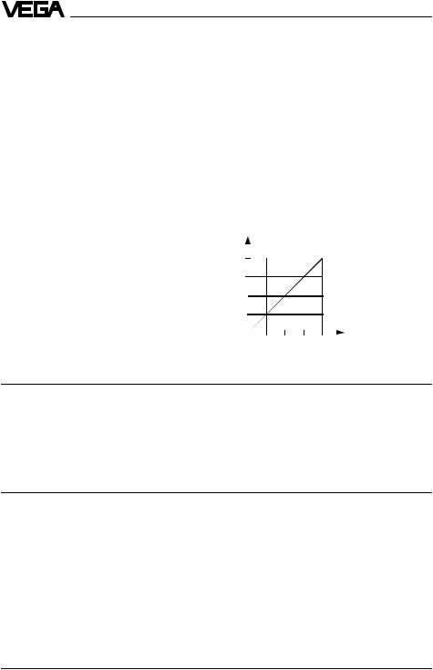
Max. permissible load |
dependent on the supply voltage |
||
|
|
(see load diagram) |
|
|
|
in Ohm |
1000 |
|
|
750 |
|
Load RL total
500
250
0 
12 18 24 30 36
|
Voltage of the external energy UH in Volts |
Indicating and adjustment circuit |
|
For connection to |
VEGADIS 10 and/or the indicating module |
Data transmission |
digital |
Connection cable |
4-wire (standard cable) |
Cable length |
max. 25 m |
Transmission reaction
Measuring ranges |
|
|
Min. pressure |
10 mbarabs |
|
Zero |
-20 % … +95 % adjustable of nominal range |
|
Span |
3,3 % … 120 % adjustable of nominal range |
|
Turn up |
up to +95 % |
|
Turn down |
up to 1 |
: 30 |
Recommended turn down: |
|
|
Accuracy class 0,25 |
up to 1 |
: 5 |
Accuracy class 0,1 |
up to 1 |
: 10 |
6 |
VEGABAR 20 |

Product description
Measuring range
Nominal measuring |
Gauge pressure |
|
Low pressure |
||
|
|||||
range |
resistance 1) |
|
resistance |
||
Gauge pressure |
|
|
|
|
|
0 |
… 0,1 bar |
10 |
bar |
|
-0,1 bar |
0 |
… 0,2 bar |
15 |
bar |
|
-0,2 bar |
|
|
|
|
|
|
0 |
… 0,4 bar |
20 |
bar |
|
-0,4 bar |
0 |
… 1,0 bar |
25 |
bar |
|
-1,0 bar |
0 |
… 2,5 bar |
35 |
bar |
|
-1,0 bar |
0 |
… 5,0 bar |
45 |
bar |
|
-1,0 bar |
0 |
… 10,0 bar |
60 |
bar |
|
-1,0 bar |
|
|
|
|
|
|
0 |
… 20,0 bar |
90 |
bar |
|
-1,0 bar |
0 |
… 40,0 bar |
140 bar |
|
-1,0 bar |
|
|
|
|
|
|
|
0 |
… 60,0 bar |
200 bar |
|
-1,0 bar |
|
-0,05 … 0,05 bar |
10 |
bar |
|
-0,1 bar |
|
-0,1 … +0,1 bar |
15 |
bar |
|
-0,2 bar |
|
-0,2 … +0,2 bar |
20 |
bar |
|
-0,4 bar |
|
-0,5 … +0,5 bar |
25 |
bar |
|
-1,0 bar |
|
-1,0 … +0,0 bar |
25 |
bar |
|
-1,0 bar |
|
|
|
|
|
|
|
-1,0 … +1,5 bar |
35 |
bar |
|
-1,0 bar |
|
-1,0 … +4,0 bar |
45 |
bar |
|
-1,0 bar |
|
|
|
|
|
|
|
-1,0 … +10,0 bar |
60 |
bar |
|
-1,0 bar |
|
-1,0 … +20,0 bar |
90 |
bar |
|
-1,0 bar |
|
-1,0 … +40,0 bar |
140 bar |
|
-1,0 bar |
||
-1,0 … +60,0 bar |
200 bar |
|
-1,0 bar |
||
Absolute pressure |
|
|
|
|
|
0 |
… 1,0 bar |
25 |
bar |
|
|
0 |
… 2,5 bar |
35 |
bar |
|
|
0 |
… 5,0 bar |
45 |
bar |
|
|
0 |
… 10,0 bar |
60 |
bar |
|
|
0 |
… 20,0 bar |
90 |
bar |
|
|
0 |
… 40,0 bar |
140 bar |
|
|
|
|
|
|
|
|
|
0 |
… 60,0 bar |
200 bar |
|
|
|
1) Note nominal pressure stage of the process connection!
VEGABAR 20 |
7 |

Product description
Measuring accuracy (similar to DIN 16 086, DIN V 19 259 - 1 and IEC 770)
Deviation
Reference conditions (acc. to IEC 770)
-temperature
-air pressure
Determination of characteristics Characteristics
Deviation in characteristics 1)
-accuracy class 0,25
-accuracy class 0,1 Hysteresis 1) Repeatability 1)
Influence of the ambient temperature
18°C … 30°C rel. humidity 860 kPa … 1060 kPa
limit point adjustment acc. to DIN 16 086 linear
<0,25 %
<0,1 %
<0,02 %
<0,02 %
Average temperature coefficient |
|
|
of the zero signal 1) 2) |
|
|
- |
accuracy class 0,25 |
< 0,15 %/10 K |
- |
accuracy class 0,1 |
< 0,05 %/10 K |
Long-term stability |
|
|
Long-term drift of the zero signal 1) 3) |
< 0,1 % |
|
Other actuating variables |
|
|
Calibration position |
standing, diaphragm points downwards |
|
Influence of the installation position |
< 0,2 mbar |
|
Vibration resistance |
mechanical vibrations with 4 g and |
|
|
|
5 … 100 Hz, tested acc. to the regulations of |
|
|
German Lloyd GL-characteristics 2 |
Operating conditions
Product
Aggregate conditions |
gas, steam, liquid up to high viscosity |
|
also abrasive and aggressive with suitable |
|
material selection of wetted parts |
|
acc. to order code |
Ambient conditions |
|
Ambient temperature |
-40°C … +85°C |
- indicating module |
-20°C … +70°C |
Storage and transport temperature |
-40°C … +85°C |
Product temperature |
-40°C … +100°C |
1)Relating to the nominal measuring range.
2)In the compensated temperature range of 0°C … +80°C, reference temperature 20°C.
3)Acc. to IEC 770, point 6.1.2 relating to the nominal measuring range.
8 |
VEGABAR 20 |
Loading...