


 Loading...
Operating Instructions
VEGADIS 62
Document ID:
36469
Indication and adjustment

Contents
Contents
1About this document
|
F |
|
4 |
1.1 |
|
unction. . . . . . . . . . . . . . . . . . . . . . . . . . . . . . . . . . |
|
|
T |
|
4 |
1.2 |
|
arget group . . . . . . . . . . . . . . . . . . . . . . . . . . . . . . |
|
|
S |
4 |
|
1.3 |
|
ymbolism used. . . . . . . . . . . . . . . . . . . . . . . . . . . . |
|
2For your safety
|
A |
|
|
5 |
2.1 |
uthorised personnel . |
. . . . . . . . . . . . . . . . . . . . . . . |
|
|
|
A |
|
|
5 |
2.2 |
ppropriate use . . . . . |
. . . . . . . . . . . . . . . . . . . . . . . |
|
|
|
W |
|
|
5 |
2.3 |
arning about misuse |
. . . . . . . . . . . . . . . . . . . . . . . |
|
|
2.4 |
General safety instructions . . . . . . . . . . . . . . . . . . . . |
5 |
||
2.5 |
CE conformity . . . . . . |
. . . . . . . . . . . . . . . . . . . . . . . |
6 |
|
|
F fi |
NAMUR |
|
6 |
2.6 |
ul llment of |
|
recommendations . . . . . . . . . . |
|
|
E |
|
|
6 |
2.7 |
nvironmental instructions. . . . . . . . . . . . . . . . . . . . . |
|
||
3Product description
|
S |
7 |
|
3.1 |
|
tructure . . . . . . . . . . . . . . . . . . . . . . . . . . . . . . . . . |
|
|
P |
|
8 |
3.2 |
|
rinciple of operation . . . . . . . . . . . . . . . . . . . . . . . . |
|
|
P |
|
9 |
3.3 |
|
ackaging, transport and storage . . . . . . . . . . . . . . . |
|
4Mounting
4.1 General instructions . . . . . . . . . . . . . . . . . . . . . . . . . 11 4.2 Instructions for installation . . . . . . . . . . . . . . . . . . . . . 11
5Connecting to power supply
|
P |
|
|
|
13 |
5.1 |
reparing the connection . . . . . . . . . . . . . . . . . . . . . |
|
|||
|
C |
|
|
|
14 |
5.2 |
|
onnection technology and steps . . . . . . . . . . . . . . . |
|
||
|
W |
|
|
17 |
|
5.3 |
|
iring plan. |
. . . . . |
. . . . . . . . . . . . . . . . . . . . . . . . . . |
|
|
C |
|
HART |
|
17 |
5.4 |
|
onnection |
|
standard. . . . . . . . . . . . . . . . . . . . |
|
|
C |
|
HART |
|
18 |
5.5 |
|
onnection |
|
multidrop . . . . . . . . . . . . . . . . . . . |
|
|
C |
|
|
|
20 |
5.6 |
|
onnection signal conditioning instruments . . . . . . . . |
|
||
|
S |
|
|
|
21 |
5.7 |
witch-on phase. . |
. . . . . . . . . . . . . . . . . . . . . . . . . . |
|
||
6Set parameters
6.1 Adjustment system . . . . . . . . . . . . . . . . . . . . . . . . . . 22 6.2 Modes . . . . . . . . . . . . . . . . . . . . . . . . . . . . . . . . . . . 23 6.3 Parameter description . . . . . . . . . . . . . . . . . . . . . . . . 24
7Set up sensors
7.1 Adjust the sensor . . . . . . . . . . . . . . . . . . . . . . . . . . . 35 7.2 Scale the indication . . . . . . . . . . . . . . . . . . . . . . . . . 35 7.3 Correct sensor adjustment . . . . . . . . . . . . . . . . . . . . 37 7.4 PACTware/DTM and PLICSCOM . . . . . . . . . . . . . . . 37
8Diagnosis and service
8.1 Maintenance . . . . . . . . . . . . . . . . . . . . . . . . . . . . . . 39 8.2 Error messages . . . . . . . . . . . . . . . . . . . . . . . . . . . . 39 8.3 Remove interferences . . . . . . . . . . . . . . . . . . . . . . . . 40 8.4 How to proceed in case of repair. . . . . . . . . . . . . . . . 40
2 |
VEGADIS 62 |
120329-EN-36469

36469-EN-120329
VEGADIS 62
Contents
9Dismounting
9.1 |
|
Dismounting steps . . . . . . . . . . . . . . . . . . . . . . . . . . |
42 |
9.2 |
Disposal . . . . . . . . . . . . . . . . . . . . . . . . . . . . . . . . . |
42 |
|
10 Supplement |
|
||
10.1 |
T |
43 |
|
echnical data . . . . . . . . . . . . . . . . . . . . . . . . . . . . . |
|
||
10.2 |
HART communication . . . . . . . . . . . . . . . . . . . . . . . . |
45 |
|
10.3 |
Dimensions . . . . . . . . . . . . . . . . . . . . . . . . . . . . . . . |
48 |
|
Safety instructions for Ex areas
Please note the Ex-specific safety information for installation and operation in Ex areas. These safety instructions are part of the operating instructions manual and come with the Ex-approved instruments.
Editing status: 2012-03-19
3
1 About this document
1 About this document
1.1 Function
This operating instructions manual provides all the information you need for mounting, connection and setup as well as important instructions for maintenance and fault rectification. Please read this information before putting the instrument into operation and keep this manual accessible in the immediate vicinity of the device.
1.2 Target group
This operating instructions manual is directed to trained qualified personnel. The contents of this manual should be made available to these personnel and put into practice by them.
1.3 Symbolism used
Information, tip, note
This symbol indicates helpful additional information.
Caution: If this warning is ignored, faults or malfunctions can result.
Warning: If this warning is ignored, injury to persons and/or serious damage to the instrument can result.
Danger: If this warning is ignored, serious injury to persons and/or destruction of the instrument can result.
Ex applications
This symbol indicates special instructions for Ex applications.
•List
The dot set in front indicates a list with no implied sequence.
àAction
This arrow indicates a single action.
1Sequence
Numbers set in front indicate successive steps in a procedure.
120329-EN-36469
4 |
VEGADIS 62 |

36469-EN-120329
VEGADIS 62
2 For your safety
2 For your safety
2.1 Authorised personnel
All operations described in this operating instructions manual must be carried out only by trained specialist personnel authorised by the plant operator.
During work on and with the device the required personal protective equipment must always be worn.
2.2 Appropriate use
The VEGADIS 62 is an indicating and adjustment unit without external energy for looping into 4 … 20 mA/HART circuits.
You can find detailed information on the application range in chapter
"Product description".
Operational reliability is ensured only if the instrument is properly used according to the specifications in the operating instructions manual as well as possible supplementary instructions.
2.3 Warning about misuse
Inappropriate or incorrect use of the instrument can give rise to application-specific hazards, e.g. vessel overfill or damage to system components through incorrect mounting or adjustment.
2.4 General safety instructions
This is a state-of-the-art instrument complying with all prevailing regulations and guidelines. The instrument must only be operated in a technically flawless and reliable condition. The operator is responsible for the trouble-free operation of the instrument.
During the entire duration of use, the user is obliged to determine the compliance of the necessary occupational safety measures with the current valid rules and regulations and also take note of new regulations.
The safety instructions in this operating instructions manual, the national installation standards as well as the valid safety regulations and accident prevention rules must be observed by the user.
For safety and warranty reasons, any invasive work on the device beyond that described in the operating instructions manual may be carried out only by personnel authorised by the manufacturer. Arbitrary conversions or modifications are explicitly forbidden.
The safety approval markings and safety tips on the device must also be observed.
5

2 For your safety
2.5 CE conformity
The device fulfills the legal requirements of the applicable EC guidelines. By a xing the CE marking, we confirm successful testing of the product.
You can find the conformity certificate in the download section under www.vega.com.
2.6 Fulfillment of NAMUR recommendations
The device fulfills the requirements of the applicable NAMUR recommendations.
2.7 Environmental instructions
Protection of the environment is one of our most important duties. That is why we have introduced an environment management system with the goal of continuously improving company environmental protection. The environment management system is certified according to DIN EN ISO 14001.
Please help us fulfil this obligation by observing the environmental instructions in this manual:
•Chapter "Packaging, transport and storage"
•Chapter "Disposal"
120329-EN-36469
6 |
VEGADIS 62 |
36469-EN-120329
|
|
3 Product description |
|
|
3 Product description |
|
|
3.1 Structure |
Constituent parts |
The indicating and adjustment unit VEGADIS 62 consists of a housing |
|
|
|
with a terminal insert as well as an integrated indicating and |
|
|
adjustment module. Dependent on the order specification, a mounting |
|
|
adapter for wall, carrier rail or tube mounting belongs to the housing. |
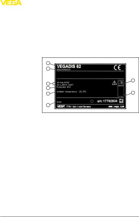
Type label |
The type label on the housing contains the most important data for |
|
|
|
identification and use of the instrument: |
Serial number
Scope of the operating instructions manual
1 |
2 |
3 |
4 |
8 |
5 |
7 |
|
6 |
Fig. 1: Structure of the type label (example)
1 Instrument type
2Product code
3 Voltage supply/Signal output
4Protection rating
5 Ambient temperature
6Order number
7 Serial number of the instrument
8Document ID
With the serial number of the instrument on the type label you have access to the following data on our homepage:
•Article number of the instrument (HTML)
•Delivery date (HTML)
•Order-specific instrument features (HTML)
•Operating instructions at the time of shipment (PDF)
•Order-specific sensor data for an electronics exchange (XML)
•Test certificate "Measuring Accuracy" (PDF)
Go to www.vega.com, "Service" "VEGA Tools" and "serial number search".
This operating instructions manual applies to the following instrument versions:
•Software from 2.00
•Software from 2.10 (with the functions Password and Logout)
VEGADIS 62 |
7 |
3 Product description
Scope of delivery |
The scope of delivery encompasses: |
|
• Indicating and adjustment unit |
|
• Documentation |
|
- this operating instructions manual |
|
- Ex-specific "Safety instructions" (with Ex versions) |
|
- if necessary, further certificates |
|
3.2 Principle of operation |
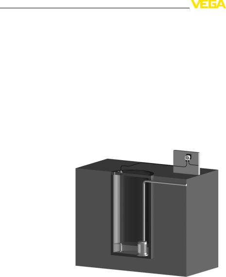
Application area |
The VEGADIS 62 is an external indicating and adjustment unit without |
|
external energy for 4 … 20 mA/HART sensors. The instrument is used |
|
for remote measured value indication and adjustment. It is looped in |
|
any position directly into the signal cable. |
|
The housing of VEGADIS 62 contains a filter element for ventilation. |
|
Hence the insturment is also used for atmospheric pressure |
|
compensation of a connected suspension pressure transmitter |
|
VEGAWELL 52. |
|
|
|
|
|
Fig. 2: Connection of the VEGADIS 62 to a suspension pressure transmitter |
|
The VEGADIS 62 can be also used as external indication for a four- |
|
wire sensor or a VEGAMET signal conditioning instrument with active |
|
4 … 20 mA output. |
Operation |
The VEGADIS 62 is suitable for operation of all continuously |
|
measuring VEGA sensors with HART output > 5.0: |
|
|
8 |
VEGADIS 62 |
120329-EN-36469

Modes
Packaging
36469-EN-120329
VEGADIS 62
3 Product description
•Radar and ultrasonic sensors
•Sensors with guided microwave
•Capacitive probes
•Pressure transmitter
•Previous instrument versions (replacement for VEGADIS 12)
The operation of respective sensors from other manufacturers is also possible.
The VEGADIS 62 acts like a HART handheld with limited functions. The following adjustment functions are available:
•Min./Max. adjustment
•zero/span adjustment (live adjustment)
•Damping
Basic mode: when used in a 4 … 20 mA signal cable, the VEGADIS 62 works as a pure indicating instrument. It measures the current in the current loop and shows it as digital value as well as via a bargraph. All settings of VEGADIS 62 are carried out manually via the buttons in the front.
Adjustment volume: Indication scaling
HART standard: when used with a 4 … 20 mA/HART sensor, the VEGADIS 62 operates as automatic indicating and HART adjustment instrument. The VEGADIS 62 powered via the current loop listens continuously to the HART communication of the control system with the sensor. Changes of unit and/or measuring range are adapted automatically.
The parameter adjustment of the sensor is carried out via HART communication. During the parameter adjustment, the VEGADIS 62 operates as a Secondary Master to the sensor.
Adjustment volume: Sensor functions, indication scaling
HART multidrop: The VEGADIS 62 can also be used as indicator for a bus participant on a HART multidrop system. For this purpose, it is looped into the bus and the address of the participant is set in the VEGADIS 62. The instrument reads out the measured values with unit via the HART signal and displays them.
Adjustment volume: Sensor function damping, indication scaling
3.3 Packaging, transport and storage
Your instrument was protected by packaging during transport. Its capacity to handle normal loads during transport is assured by a test according to DIN EN 24180.
The packaging of standard instruments consists of environmentfriendly, recyclable cardboard. For special versions, PE foam or PE foil is also used. Dispose of the packaging material via specialised recycling companies.
9

3 Product description
Transport |
Transport must be carried out under consideration of the notes on the |
|
transport packaging. Nonobservance of these instructions can cause |
|
damage to the device. |
Transport inspection |
The delivery must be checked for completeness and possible transit |
|
damage immediately at receipt. Ascertained transit damage or |
|
concealed defects must be appropriately dealt with. |
Storage |
Up to the time of installation, the packages must be left closed and |
|
stored according to the orientation and storage markings on the |
|
outside. |
|
Unless otherwise indicated, the packages must be stored only under |
|
the following conditions: |
|
• Not in the open |
|
• Dry and dust free |
|
• Not exposed to corrosive media |
|
• Protected against solar radiation |
|
• Avoiding mechanical shock and vibration |
Storage and transport |
• Storage and transport temperature see chapter "Supplement - |
temperature |
Technical data - Ambient conditions" |
|
• Relative humidity 20 … 85 % |
120329-EN-36469
10 |
VEGADIS 62 |

|
|
4 Mounting |
|
4 |
Mounting |
|
4.1 |
General instructions |
Moisture |
Use the recommended cables (see chapter "Connecting to power |
|
|
supply") and tighten the cable gland. |
|
|
You can give your instrument additional protection against moisture |
|
|
penetration by leading the connection cable downward in front of the |
|
|
cable entry. Rain and condensation water can thus drain o . This |
|
|
applies mainly to outdoor mounting as well as installation in areas |
|
|
where high humidity is expected (e.g. through cleaning processes) or |
|
|
on cooled or heated vessels. |
|
|
4.2 |
Instructions for installation |
Wall mounting |
VEGADIS 62 for wall mounting is supplied with a mounting socket. |
|
36469-EN-120329
mm7 |
(0.28") |
12 mm |
|
(0.47") |
|
62 mm |
(2.44") |
85 mm (3.35") |
Fig. 3: VEGADIS 62 for wall mounting, bottom view of mounting plate.
1Drilling dimensions
Carrier rail mounting VEGADIS 62 for mounting on carrier rail is supplied with a mounting adapter.
1 2
Fig. 4: VEGADIS 62 for carrier rail mounting
1 Carrier rail adapter
2Carrier rail
VEGADIS 62 |
11 |
4 Mounting
Tube mounting |
VEGADIS 62 for tube mounting is supplied with a meas. instrument |
|
holder and four screws M5 x 12 as mounting accessory. The meas. |
|
instrument holder is mounted to the socket of VEGADIS 62. |
|
3 |
1 |
2 |
Fig. 5: VEGADIS 62 for tube mounting
14 screws M5 x 12
2 Measuring instrument holder
3Tube
120329-EN-36469
12 |
VEGADIS 62 |

36469-EN-120329
|
|
5 Connecting to power supply |
|
|
5 Connecting to power supply |
|
|
5.1 Preparing the connection |
Safety instructions |
Always keep in mind the following safety instructions: |
|
|
|
• Connect only in the complete absence of line voltage |
|
|
• If voltage surges are expected, install overvoltage arresters |
Voltage supply |
Power supply and current signal are carried on the same two-wire |
|
|
|
cable. The voltage supply range can di er depending on the sensor. |
|
|
The data for power supply are specified in chapter "Technical data". |
|
|
Provide a reliable separation between the supply circuit and the mains |
|
|
circuits according to DIN VDE 0106 part 101. |
|
|
Keep in mind the following additional factors that influence the |
|
|
operating voltage: |
|
|
• Output voltage of the power supply unit can be lower under |
|
|
nominal load (with a sensor current of 20.5 mA resp. 22 mA in |
|
|
case of fault message) |
|
|
• Influence of additional instruments in the circuit (see load values in |
|
|
chapter "Technical data") |
|
|
Operation of VEGADIS 62 in a HART multidrop system with the signal |
|
|
conditioning instruments VEGAMET 625 or VEGASCAN 693 is not |
|
|
supported. |
Connection cable |
The instrument is connected with standard two-wire cable without |
|
|
|
screen. If electromagnetic interference is expected which is above the |
|
|
test values of EN 61326-1 for industrial areas, screened cable should |
|
|
be used. |
|
|
For instruments with housing and cable gland, use cable with round |
|
|
cross-section. A cable outer diameter of 5 … 9 mm (0.2 … 0.35 in) |
|
|
ensures the seal e ect of the cable gland. If you are using cable with a |
|
|
di erent diameter, exchange the seal or use a suitable cable gland. |
|
|
We generally recommend the use of screened cable for HART |
|
|
multidrop mode. |
Cable gland ½ NPT |
With plastic housing, the NPT cable gland or the Conduit steel tube |
|
|
|
must be screwed without grease into the threaded insert. |
|
|
Max. torque for all housings see chapter "Technical data" |
Cable screening and |
If screened cable is necessary, connect the cable screen on both ends |
|
grounding |
to ground potential. In the sensor, the screen must be connected |
|
|
|
directly to the internal ground terminal. The ground terminal on the |
|
|
outside of the housing must be connected to the potential equalisation |
|
|
(low impedance). |
VEGADIS 62 |
13 |
5 Connecting to power supply
|
|
|
|
|
If potential equalisation currents are expected, the connection on the |
|
|
|
|
|
processing side must be made via a ceramic capacitor (e. g. 1 nF, |
|
|
|
|
|
1500 V). The low frequency potential equalisation currents are thus |
|
|
|
|
|
suppressed, but the protective e ect against high frequency interfer- |
|
|
|
|
|
ence signals remains. |
|
|
|
|
|
Warning: |
|
|
|
|
|
Significant potential di erences exist inside galvanization plants as |
|
|
|
|
|
well as on vessels with cathodic corrosion protection. Considerable |
|
|
|
|
|
equalisation currents can flow over the cable screen if the screen is |
|
|
|
|
|
grounded on both ends. |
|
|
|
|
|
To avoid this in such applications, the cable screen must be connected |
|
|
|
|
|
to ground potential only at one end (in the switching cabinet). The |
|
|
|
|
|
cable screen must not be connected to the internal ground terminal in |
|
|
|
|
|
the sensor and the outer ground terminal on the housing must not be |
|
|
|
|
|
connected to the potential equalisation! |
|
|
|
|
|
Information: |
|
|
|
|
|
The metal parts of the instrument (antenna, transmitter, concentric |
|
|
|
|
|
tube, etc.) are conductive connected with the inner and outer ground |
|
|
|
|
|
terminal on the housing. This connection exists either directly metallic |
|
|
|
|
|
or with instruments with external electronics via the screen of the |
|
|
|
|
|
special connection cable. |
|
|
|
|
|
You can find specifications to the potential connections within the |
|
|
|
|
|
instrument in chapter "Technical data". |
|
|
|
|
|
5.2 Connection technology and steps |
Connection technology |
The connection of the signal cable is carried out via spring-loaded |
||||
|
|
|
|
|
terminals in the housing. |
|
|
|
|
|
The indicating and adjustment module is connected via a cable with |
|
|
|
|
|
coupling to the housing. |
Connection procedure |
Proceed as follows: |
||||
|
|
|
|
|
1 Unscrew the housing cover |
120329-EN-36469
14 |
VEGADIS 62 |
5 Connecting to power supply
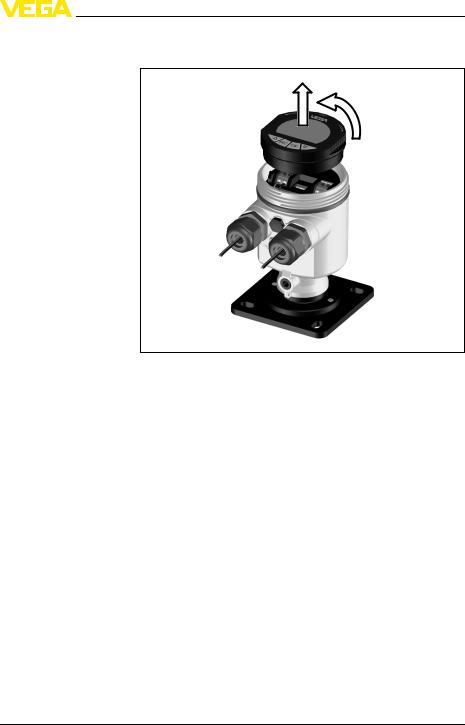
2Remove the indicating and adjustment module by turning it slightly to the left
Fig. 6: Dismounting of the indicating and adjustment module
3Loosen compression nut of the cable glands
4Remove approx. 10 cm (4 in) of the signal cable mantle, strip approx. 1 cm (0.4 in) insulation from the ends of the individual wires
36469-EN-120329
VEGADIS 62 |
15 |
5 Connecting to power supply
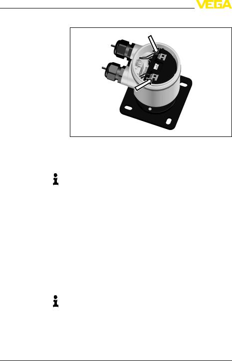
5Insert the cable into the sensor through the cable entry
Fig. 7: Connection steps 5 and 6
6Insert the wire ends into the terminals according to the wiring plan
Note:
Solid cores as well as flexible cores with cable end sleeves are inserted directly into the terminal openings. In case of flexible cores without end sleeves, press the terminal with a small screwdriver; the terminal opening is freed. When the screwdriver is released, the terminal closes again.
7Check the hold of the wires in the terminals by lightly pulling on them
8Connect the screen to the internal ground terminal, connect the outer ground terminal to potential equalisation
9Attach the indicating and adjustment module again and turn it slightly to the right
10Tighten the compression nut of the cable glands. The seal ring must completely encircle the cable
11Screw the housing cover back on
The electrical connection is finished.
Note:
The terminal block is pluggable and can be removed from the electronics. To do this, lift the terminal block with a small screwdriver and pull it out. When inserting the terminal block again, you should hear it snap in.
16 |
VEGADIS 62 |
120329-EN-36469
Loading...