


Model IP-2002
Radio Control Console
Technical Manual
P.N. 804004 REV A
July 27, 2004
Remote Control Console |
I |
|||
Table of Contents |
|
|||
1 |
INTRODUCTION ............................................................................................................................................... |
1 |
||
2 |
HARDWARE OVERVIEW ............................................................................................................................... |
1 |
||
|
2.1 MAIN PROCESSOR PCB .................................................................................................................................. |
1 |
||
|
2.2 |
KEYPAD PCB AND DISPLAY........................................................................................................................... |
1 |
|
3 |
CONTROLS AND INDICATORS..................................................................................................................... |
2 |
||
|
3.1 |
FRONT PANEL................................................................................................................................................. |
2 |
|
|
3.1.1 |
Common Controls and Indicators ......................................................................................................... |
2 |
|
|
|
3.1.1.1 |
VU Meter: .......................................................................................................................................................... |
2 |
|
|
3.1.1.2 |
Program 1-4: ...................................................................................................................................................... |
3 |
|
|
3.1.1.3 |
DTMF Keypad:.................................................................................................................................................. |
3 |
|
|
3.1.1.4 |
Supervisory button:............................................................................................................................................ |
3 |
|
|
3.1.1.5 |
Menu button:...................................................................................................................................................... |
3 |
|
|
3.1.1.5.1 Cross Patch.................................................................................................................................................. |
3 |
|
|
|
3.1.1.6 Channel UP/DOWN buttons (C▲& C▼): ........................................................................................................ |
3 |
|
|
|
3.1.1.7 |
Scan button: ....................................................................................................................................................... |
3 |
|
|
3.1.1.8 |
Channel button:.................................................................................................................................................. |
3 |
|
|
3.1.1.9 Group UP/DOWN buttons (G▲& G▼):........................................................................................................... |
4 |
|
|
|
3.1.1.10 |
Function Buttons F1-F4:................................................................................................................................ |
4 |
|
|
3.1.1.11 |
Line Buttons LN1-LN2: ................................................................................................................................ |
4 |
|
|
3.1.1.12 |
Volume Control:............................................................................................................................................ |
4 |
|
|
3.1.1.13 |
Monitor:......................................................................................................................................................... |
4 |
|
|
3.1.1.14 |
Intercom (IC):................................................................................................................................................ |
4 |
|
|
3.1.1.15 |
Panel PTT Pushbutton: .................................................................................................................................. |
4 |
|
|
3.1.1.16 |
Transmit LED:............................................................................................................................................... |
4 |
|
3.2 REAR PANEL CONNECTIONS ........................................................................................................................... |
4 |
||
|
3.2.1 |
Rear Panel Ports ................................................................................................................................... |
5 |
|
4 |
OPERATION....................................................................................................................................................... |
5 |
||
|
4.1 |
RADIO LINES .................................................................................................................................................. |
5 |
|
|
4.1.1 |
Selecting: ............................................................................................................................................... |
5 |
|
|
4.1.2 |
Changing Function Tones: .................................................................................................................... |
5 |
|
|
4.1.3 |
Muting Unselected Lines: ...................................................................................................................... |
5 |
|
|
4.1.4 |
Releasing a Line: ................................................................................................................................... |
6 |
|
|
4.1.5 |
Supervisory Control Button:.................................................................................................................. |
6 |
|
|
4.1.6 |
TX ALL Function (No button): .............................................................................................................. |
6 |
|
|
4.1.7 |
Intercom to parallel console:................................................................................................................. |
6 |
|
|
4.1.8 |
Answering a Phone call......................................................................................................................... |
6 |
|
|
4.1.9 |
Placing a call......................................................................................................................................... |
6 |
|
|
4.1.10 |
Putting a Phone line On-Hold ............................................................................................................... |
6 |
|
|
4.1.11 |
Muting a phone Line: ............................................................................................................................ |
6 |
|
|
4.1.12 |
Sending a Hook-Flash ........................................................................................................................... |
6 |
|
|
4.1.13 |
Releasing a Phone Line:........................................................................................................................ |
6 |
|
|
4.1.14 |
General Display Indications: ................................................................................................................ |
6 |
|
5 |
PROGRAMMING............................................................................................................................................... |
7 |
||
|
5.1 ENTERING THE SETUP MODE .......................................................................................................................... |
7 |
||
|
5.2 SETTING THE SYSTEM CLOCK......................................................................................................................... |
7 |
||
|
5.3 |
SETTING THE PIN NUMBER............................................................................................................................. |
7 |
|
|
5.4 |
SETTING THE BASIC IP INFORMATION ............................................................................................................. |
8 |
|
|
5.5 |
ENTERING IP-2002 WEB SETUP ..................................................................................................................... |
9 |
|
|
5.5.1 |
Orange Crossover Cable ....................................................................................................................... |
9 |
|
|
5.6 BASIC ETHERNET SETUP............................................................................................................................... |
10 |
||
|
5.6.1 |
Use DHCP Server: .............................................................................................................................. |
10 |
|
|
5.6.2 |
Unit IP Address: .................................................................................................................................. |
10 |
|
|
5.6.3 |
Subnet Mask: ....................................................................................................................................... |
11 |
|
|
5.6.4 |
Gateway Address:................................................................................................................................ |
11 |
|
II |
|
|
Vega’s IP-2002 |
5.6.5 |
|
DNS Addresses 1-2:............................................................................................................................. |
11 |
5.6.6 |
|
SNTP Address:..................................................................................................................................... |
11 |
5.6.7 |
|
SNTP Update Interval: ........................................................................................................................ |
11 |
5.6.8 |
|
SNTP Local Time Offset: ..................................................................................................................... |
11 |
5.6.9 |
|
Packet Delay Before Playback: ........................................................................................................... |
11 |
5.6.10 |
QOS Bits:............................................................................................................................................. |
11 |
|
5.6.11 |
Local IP Addresses:............................................................................................................................. |
12 |
|
5.7 |
MULTICAST SETUP ....................................................................................................................................... |
12 |
|
5.7.1 |
|
Enable via Ethernet: ............................................................................................................................ |
12 |
5.7.2 |
|
Channel Name: .................................................................................................................................... |
12 |
5.7.3 |
|
Multicast Address: ............................................................................................................................... |
12 |
5.7.4 |
|
RX and TX Ports:................................................................................................................................. |
12 |
5.7.5 |
|
Channel Hops:..................................................................................................................................... |
12 |
5.8 |
ANI DIRECTORY SETUP ............................................................................................................................... |
13 |
|
5.9 |
PER LINE SETUP PARAMETERS ..................................................................................................................... |
13 |
|
5.9.1 |
|
Line Enabled: ...................................................................................................................................... |
14 |
5.9.2 |
|
Duplex Enable: .................................................................................................................................... |
14 |
5.9.3 |
|
Crosspatch Open Time: ....................................................................................................................... |
14 |
5.9.4 |
|
Select Call String:................................................................................................................................ |
14 |
5.9.5 |
|
Select Call Open Time:........................................................................................................................ |
14 |
5.9.6 |
|
Disable Mute: ...................................................................................................................................... |
14 |
5.9.7 |
|
Min Mute Level:................................................................................................................................... |
14 |
5.9.8 |
|
TX Enabled:......................................................................................................................................... |
14 |
5.9.9 |
|
Network Phone Enable:....................................................................................................................... |
14 |
5.9.10 |
Local Phone Line: ............................................................................................................................... |
14 |
|
5.9.11 |
F-Tone 1-100 Enable: ......................................................................................................................... |
14 |
|
5.9.12 |
Ftone1-100 Alphanumeric:.................................................................................................................. |
14 |
|
5.9.13 |
RX Block:............................................................................................................................................. |
14 |
|
5.9.14 |
TX Block: ............................................................................................................................................. |
15 |
|
5.9.15 |
Pairs/Wildcard: ................................................................................................................................... |
15 |
|
5.10 GENERAL GAIN SETUP.................................................................................................................................. |
15 |
||
5.11 GLOBAL SYSTEM SETUP 1 ............................................................................................................................ |
16 |
||
5.11.1 |
Supervisor Enable: .............................................................................................................................. |
16 |
|
5.11.2 |
Supervisor Timeout: ............................................................................................................................ |
16 |
|
5.11.3 |
TX Delay:............................................................................................................................................. |
16 |
|
5.11.4 |
Auto Monitor Enable:.......................................................................................................................... |
16 |
|
5.11.5 |
CRP Timeout: ...................................................................................................................................... |
16 |
|
5.11.6 |
Console Name: .................................................................................................................................... |
17 |
|
5.11.7 |
CRP Delay:.......................................................................................................................................... |
17 |
|
5.11.8 |
Mute UNSEL w/ PTT:.......................................................................................................................... |
17 |
|
5.11.9 |
Line Tape Output Mix:......................................................................................................................... |
17 |
|
5.11.10 |
Line Tape with Volume:................................................................................................................... |
17 |
|
5.11.11 |
Handset or Headset RX routing: ..................................................................................................... |
17 |
|
5.11.12 |
Summed RX to Handset or Headset: ............................................................................................... |
17 |
|
5.11.13 |
Network Phone Ring Type:.............................................................................................................. |
17 |
|
5.11.14 |
Panel PTT Default Mic:................................................................................................................... |
17 |
|
5.11.15 |
DTMF Keypad Enable:.................................................................................................................... |
17 |
|
5.11.16 |
DTMF Flywheel: ............................................................................................................................. |
17 |
|
5.11.17 |
DTMF On Time: .............................................................................................................................. |
18 |
|
5.11.18 |
DTMF Off Time: .............................................................................................................................. |
18 |
|
5.11.19 |
DTMF Level: ................................................................................................................................... |
18 |
|
5.11.20 |
DTMF Sidetone: .............................................................................................................................. |
18 |
|
5.11.21 |
DTMF Sidetone Level:..................................................................................................................... |
18 |
|
GLOBAL SYSTEM SETUP 2 ........................................................................................................................................ |
18 |
||
5.11.22 |
Alert Tone Buttons Setup:................................................................................................................ |
18 |
|
5.12 CLONE FROM OTHER CONSOLE .................................................................................................................... |
19 |
||
5.13 |
PIN CHANGE ................................................................................................................................................ |
19 |
|
5.14 SAVE TO EEPROM ...................................................................................................................................... |
20 |
||

Remote Control Console |
III |
|
5.15 |
REPROGRAMMING THE IP-2002 SOFTWARE ................................................................................................. |
20 |
6 SCHEMATICS, PARTS PLACEMENTS, AND BILLS OF MATERIAL.................................................. |
21 |
|
6.1 MAIN PROCESSOR PCB ................................................................................................................................ |
21 |
|
6.2 |
KEYPAD PCB ............................................................................................................................................... |
22 |
6.3 |
IP-2002 ASSY DRAWING ............................................................................................................................ |
23 |
7 WARRANTY, SERVICE, REPAIR AND COMMENTS.............................................................................. |
24 |
|
8 SPECIFICATIONS ........................................................................................................................................... |
25 |
|
Table of Figures |
|
|
Figure 1 Front Panel Diagram ......................................................................................................................... |
2 |
|
Figure 2 Menu Button Functions..................................................................................................................... |
3 |
|
Figure 3Cross Patch Menu .............................................................................................................................. |
3 |
|
Figure 4 Rear Panel Diagram .......................................................................................................................... |
5 |
|
Figure 5 Initial Programming Screen .............................................................................................................. |
7 |
|
Figure 6 Clock Setup Screen ........................................................................................................................... |
7 |
|
Figure 7 PIN Setup Screen .............................................................................................................................. |
7 |
|
Figure 8 PIN setup Sub-menu screens............................................................................................................ |
8 |
|
Figure 9 Main IP setup screen ......................................................................................................................... |
8 |
|
Figure 10 IP Setup Sub-menu screens............................................................................................................. |
8 |
|
Figure 11 IP-2002 Login Screen ..................................................................................................................... |
9 |
|
Figure 12 Basic Ethernet Setup Screen ......................................................................................................... |
10 |
|
Figure 13 Multicast Setup Screen.................................................................................................................. |
12 |
|
Figure 14 ANI Directory Setup Page ............................................................................................................ |
13 |
|
Figure 15 Per Line Setup Page ...................................................................................................................... |
13 |
|
Figure 16 General Gain Setup Page .............................................................................................................. |
15 |
|
Figure 17 Global System Setup Page 1 ......................................................................................................... |
16 |
|
Figure 18 Global System Setup 2 .................................................................................................................. |
18 |
|
Figure 19 Console Clone Page ...................................................................................................................... |
19 |
|
Figure 20 PIN Change Page .......................................................................................................................... |
19 |
|
Figure 21 Save To EEPROM Page................................................................................................................ |
20 |
|
VOIP Desktop Console |
1 |
1 Introduction
The IP-2002 is a unique multi-channel full-featured self-contained desktop radio control console. It will control two lines and is an Ethernet only console; you can use the Vega IP223 adapter panel enabling you to connect between the console and your base station via an Ethernet connection. The IP223 accommodates Ethernet connections for controlling two radios.
The IP-2002 sports a VF display, which provides channel alpha/numeric indication, clock and audio-level meter with a modern membrane keypad. These features allow for a more flexible dispatch environment in which the console may be installed. The dispatcher can easily operate the console while sitting or standing.
The IP-2002 will accommodate a desk microphone, along with a handset (or headset) as indicated on the side of the IP-2002 console. When a PTT occurs from either of the two microphones, the other will mute so as not to pick-up unnecessary ambient noise during transmission. When the handset is taken off hook and a line is Selected, the receive audio from that line is transferred to the earpiece. The IP-2002 also has a front panel microphone, which can be used when the handset/headset is on-hook.
The IP-2002 is a Digital Signal Processor (DSP) based design, allowing easy field programmability using a computer with installed WEB browser. Unlike other manufacturers’ equipment, no additional software is required to configure the IP-2002 console. Modifications and enhancements can generally be made via a software change only. If the user determines they require a special feature enhancement, please contact the Vega Sales Department for cost and feasibility.
2 Hardware Overview
The IP-2002 is a multi-line; multi-mode console designed specifically for medium level system requirements. All functions are housed in a single modern looking console and consist of the following sub-assemblies: Main Processing Board and Keypad/Display Board.
2.1 Main Processor PCB
The Main Processor board contains two distinct sections, the Ethernet front end and the Signal processing circuitry. The Ethernet front end consists of an ARM processor with an Ethernet MAC, connected to the Physical Interface IC and Transformer. Around the ARM processor are various peripheral devices, including FLASH and SRAM. This section controls all the Ethernet processing, such as the FTP server; web page and packet transfer for the IP-2002. The Signal processing section, featuring the TMS320C5510, is used to do all the audio. The DSP also controls all the keypad and device I/O, as well as, the LED and display drivers.
2.2 Keypad PCB and Display
The Keypad board is interfaced to the main board via a 40-pin IDC ribbon cable. The board contains the circuitry to decode the keypad matrix, and interface the DSP to the display. The display is mounted to the chassis cover with four screws and connected to Keypad PCB with a 14-pin IDC ribbon cable.

2 |
Vega’s IP-2002 |
3 Controls and Indicators
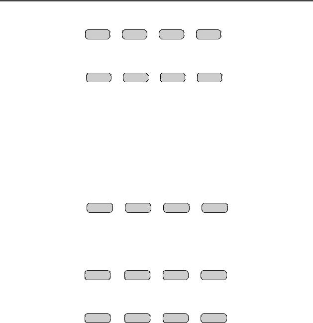
Figure 1 Front Panel Diagram
3.1 Front Panel
Figure 1 shows a view of the Front panel. The Front panel contains the user I/O. It features a Volume control, intercom and monitor functions, panel PTT with indicator, built in panel microphone, per line Select, Release and Mute functions, DTMF keypad, Supervisory, Scan, Menu and Channel which are used with the F1-F4 Function Tone selection. The IP-2002 is programmed from the front panel using the four gray soft keys located below the Vacuum Florescent LCD display. The display provides channel/numeric indication, clock and audio-level meter.
3.1.1Common Controls and Indicators
3.1.1.1 VU Meter:
Displays Selected receive and Microphone audio bus levels. This meter is shown on the top line of the display and utilizes the first 12 display elements from the upper left.

VOIP Desktop Console |
3 |
3.1.1.2 Program 1-4:
Are used as “soft” programming buttons when in the tech mode. These buttons will have different functions depending on the action required. The bottom line of the display will show their respective functions.
3.1.1.3 DTMF Keypad:
The DTMF keypad is used for transmitting DTMF digits, selecting frequencies and entering alphanumeric strings for various features.
3.1.1.4 Supervisory button:
The SUP button allows one console operator to disable any other console. The Red LED is on during supervisory and blinking when being supervised. Note, this is an IP based Supervisor mechanism. No wiring is required.
3.1.1.5 Menu button:
The Menu button will allow access to the following other features: Paging1, Instant Recall Recorder1 and CrossPatch.
M a i n M e n u |
|
|
|
PAGE |
IRR |
XP |
EXIT |
Figure 2 Menu Button Functions
3.1.1.5.1Cross Patch
Menu button used to set the single available cross patch between line 1 and 2. Pressing XP at the main menu will enable the cross patch. Once in the XP Menu, the available functions are Block and PTT.
X P M e n u |
|
|
BLK |
PTT |
EXIT |
Figure 3 Cross Patch Menu
The BLK button is used to block a receive channel that may need disabled. The PTT button is used to PTT on the cross patch. The EXIT button will exit this setup menu and disable the cross patch.
3.1.1.6 Channel UP/DOWN buttons (C▲& C▼):
Used to change selected line F-tone frequency UP or DOWN.
3.1.1.7 Scan button:
Used to turn the radios receive Scan feature on/off if available.
3.1.1.8 Channel button:
Used to change selected line F-tone frequency via the DTMF keypad. Pressing the CHAN button then two DTMF keys (0-9) changes the channel directly. Note the general sequence: CHAN,0,1 = F1; CHAN,0,2 = F2; …CHAN,9,9 = F99.
1 Not implemented on Software Version 1.0
4 |
Vega’s IP-2002 |
3.1.1.9 Group UP/DOWN buttons (G▲& G▼):
Used to change selected line Group selection UP or DOWN, Trunking feature.
3.1.1.10 Function Buttons F1-F4:
When a function button is pressed, function packet burst is sent out. When a function is selected it will light to indicate which function is chosen, a function shall remain selected until the operator changes the setting.
3.1.1.11 Line Buttons LN1-LN2:
Three buttons are available for each Line, SELect, RLS (Release) and Mute.
SELect button: When the SEL buttons is pressed that line enters the Select mode
Select LED: The Red LED under each LNx SEL Button indicates if the line is selected for transmit audio.
RLS button: The RLS button is used to release a selected line.
RLS LED: The blinking Red LED under each LNx RLS Button indicates receive audio activity on that line. A solid LED indicates that TX block is occurring.
Mute button: The Mute button is used if RX audio from that line is not to be monitored in the speaker.
Mute LED: The steady Red LED under each LNx Mute Button indicates if the line is muted from receive audio monitoring. A blinking LED indicates that RX block is occurring.
3.1.1.12 Volume Control:
Adjusts the receive speaker audio and handset earpiece level of the receive inputs of the line interfaces. A minimum volume level can be set in tech-mode, so that the console operator cannot turn the speaker volume to zero. When adjusting the level up or down, the display shows the selected level on a relative scale. If the handset is off hook, HSVOL is displayed and the handset ear volume is adjusted. Otherwise, SPKR is displayed and the speaker volume is adjusted.
Select and Unselect audio levels per line can also be set from the front panel by pressing and holding Line 1 or 2 SEL or RLS buttons and adjusting the normal volume control.
3.1.1.13 Monitor:
When the Monitor button is pressed a Monitor packet burst is sent out on the selected line. An LED indication lights while the key is pressed.
3.1.1.14 Intercom (IC):
When the Intercom button is pressed and held down the IP-2002 shall transmit audio packets marked as Intercom. Intercom is considered a Non-PTT based audio stream.
3.1.1.15 Panel PTT Pushbutton:
When pressed, audio from the Panel PTT Default microphone will be sent to all Selected lines. See Global System Setup 1 5.11.14 for programming this option.
3.1.1.16 Transmit LED:
This LED lights when any PTT source is depressed keying up the console.
3.2 Rear Panel Connections
Figure 4 shows drawing of the rear panel of the IP-2002. Each of the ports shown is discussed in detail in the following section.
VOIP Desktop Console |
5 |
Figure 4 Rear Panel Diagram
3.2.1Rear Panel Ports
Power Jack: The left most jack on the IP-2002 is the Power Jack. The power supply that is included with the unit plugs in to this location. It is a standard 2.5mm center positive plug and requires at least 12V to operate correctly.
Tape Port: This RJ-45 has Line 1 and Line 2 Tape recorder outputs. Line 1 on Pins 1,2. Line 2 on Pins 7,8. Both are 600 ohm transformer coupled outputs.
Auxiliary Port:
TX-2 and RX-2: Pins 1 and 2 provide a secondary RS-232 port.
Auxiliary PTT: Pin 3 provides and alternate or auxiliary PTT input mechanism.
Auxiliary Audio Input: Pin 4 is an audio input used as the audio source when Aux PTT is pressed. Earth Ground: Provides an Earth ground connection. Use is advised.
Data port:
TX-1 and RX-1: Pins 1 and 2 provide the primary RS-232 port for the unit. There are programming and diagnostic capabilities available when using this port. Under normal circumstances, this port is not used. No cable is provided, only the connector.
Ethernet Port: Standard RJ-45 Ethernet interface. Link and TX LED’s are built into the connector.
4 Operation
4.1 Radio Lines
4.1.1Selecting:
When the desired line Select pushbutton is momentarily pressed, the receive audio from this Selected line is placed on the speaker and the previously Selected line is disengaged. The currently Selected line name (programmable) is displayed on the screen and the line Select indicator is illuminated.
The receive audio from the selected line will be heard on the consoles speaker and can be adjusted by the selected master volume control. If the handset or headset is enabled and taken off hook, the receive audio is transferred to the earpiece, see 5.11.11.
4.1.2 Changing Function Tones:
The function tone keys are used to select a function tone for a specific line. This function tone will be remembered per line. If a group PTT is sent, the function packet that corresponds to each line will be sent on that line. If the Function button is pressed independently, a Function packet is sent. These keys are backlit with a single RED LED.
4.1.3Muting Unselected Lines:
Both lines can be Muted, when unselected, by pressing the MUTE key for that line. If the line is selected it cannot be muted. A brief line volume ON/OFF display occurs when the button is pressed.
6 |
Vega’s IP-2002 |
4.1.4Releasing a Line:
To release a radio line, simply press the RLS pushbutton for that line.
4.1.5Supervisory Control Button:
The SUP Button is used to disable all units on a particular line, by pressing the SUP Button, the Button will light and disable all connected paralleled consoles. On the consoles that are being supervised, the SUP Button will blink, if they have selected a line that the supervisor has selected
4.1.6 TX ALL Function (No button):
There is no specific button for the TX ALL function. This function is completed as follows: Press the Line 1 select button and hold, then press Line 2 select button. This will select both lines to complete the TX ALL function. No order for this press and hold sequence is required.
4.1.7Intercom to parallel console:
To intercom to a parallel console simply select a shared line and press INTERCOM.
4.1.8Answering a Phone call
To select a ringing phone line (audible and select LED blinking) simply press the desired lines Select pushbutton. The phone line will go off-hook and the receive audio is then routed to the earpiece of the handset or headset depending on which one you are currently using. Any selected radio line audio, is now routed into the speaker. If you were speaking on another selected phone line it will automatically be put on hold.
4.1.9Placing a call
To place a call, simply select a phone line and dial the number on the DTMF pad. The number dialed will be displayed.
DTMF keypad digits
0-9 = Allows direct entry of a three digit number specifying a particular phone number.
4.1.10 Putting a Phone line On-Hold
To put a line on hold simply press the select button after the call is initiated, the select button LED will blink and phone line audio will be routed to the speaker. To talk on a phone line that is already On-hold simply press the select button again.
4.1.11 Muting a phone Line:
Receive audio from phone lines On-hold are played out the speaker, undesired receiver audio may be muted by pressing that lines MUTE button. The orange LED under the MUTE pushbutton will also illuminate to indicate a muted condition.
4.1.12 Sending a Hook-Flash
To cause a hook flash (needed sometimes to transfer calls) simply press and release the RLS button.
4.1.13 Releasing a Phone Line:
To release a phone line, simply press the RLS pushbutton and hold for 1 second then release.
4.1.14 General Display Indications:
The IP-2002 will display Receive, Transmit(TX1,TX2) and Intercom(EI1,EI2) events, per line. They will appear as text on the lower right corner of the display. Receive audio will be indicated by the RLS LED flashing. The selected line will show VU indication for receive audio as well.

VOIP Desktop Console |
7 |
5 Programming
5.1 Entering the Setup Mode
Setup of the IP-2002 is almost entirely done using a web browser. The first step required during setup is to assign the IP and Mask addresses to the IP-2002. This is done through the front panel. To enter the front panel setup mode, press and hold Line 1 MUTE, and G▲, then press DTMF *. The front panel display will appear like Figure 5. From the front panel of the IP-2002, the internal clock, Ethernet parameters, and security PIN can be set.
P r o g r a m m i n g M o d e:
C L K |
IP |
PIN |
EXIT |
Figure 5 Initial Programming Screen
5.2 Setting the System Clock
Pressing PROG1 from the top-level setup menu will open the screen to set the internal Real Time Clock. Figure 6 shows the screen for the clock setup. PROG1 selects the Edit option that allows setting of the actual minutes and hours. PROG2 sets AM or PM., PROG3 selects 12 or 24-hour mode, PROG4 (back) returns to the previous setup screen in Figure 5.
C l o c k 1 2 : 0 0 A M |
12 hr |
||
E d i t |
A/P |
12/24 |
back |
Figure 6 Clock Setup Screen
5.3 Setting the PIN number
The Pin number is used to prevent unauthorized modification of operation parameters. When a PIN number is set, the IP-2002 will prompt for it before allowing entry into the setup mode. The web-based setup for the IP-2002 also has provision for a user password; it is the same four-digit value as the PIN number entered from this menu option. From Figure 5, selecting PROG3 (PIN) from the main menu will cause the IP-2002 to prompt for the new PIN number twice. If both are entered identically, the new PIN number will take affect. Figure 8 shows the two available sub-menu screen in the PIN setup.
P I N S e t u p [ -- -- -- -- |
] : |
|
N e w |
C l r |
back |
Figure 7 PIN Setup Screen
8 |
Vega’s IP-2002 |
C l e a r P I N ? |
|
YES |
NO |
N e w P I N : |
|
|
Cancel |
Figure 8 PIN setup Sub-menu screens
5.4 Setting the basic IP information
As was mentioned before, all other parameters are setup by using a browser such as Netscape or Internet Explorer. Before connecting to the console with the browser, an IP address and Mask that is compatible with the users existing network must be set. Figure 9 shows the screen selected when PROG2 (IP) is pressed from the main setup screen. See your network administrator to determine the proper values. Figure 10 shows the dotted quad editing screens for the IP and Mask.
I P S e t u p : |
|
|
|
I P |
Mask |
|
back |
|
Figure 9 Main IP setup screen |
|
|
I P : 1 7 2 . 1 9 . 1 0 0 . 1 2 3 |
|
||
Clr |
< |
> |
back |
Mask : 1 7 2 . 1 9 . 1 0 0 . 1 2 3 |
|
||
Clr |
< |
> |
back |
Figure 10 IP Setup Sub-menu screens
The following keys are used to enter the IP and Mask dotted quad once PROG1 (IP) or PROG2 (Mask) is pressed.
DTMF 0-9: |
The DTMF digits allow entry of the specific numbers. |
DTMF A: |
DTMF * or “A” is the decimal point used in dotted quad. |
PROG4: |
The “back” key is pressed when the dotted quad has been entered. |
PROG1: |
The “Clr” function clears the current entered value and starts over. |
PROG2: |
The < “backspace” function deletes the last entered number. |
PROG3: |
The > “forward space” function steps past the next number if necessary. |
VOIP Desktop Console |
9 |
Once these values have been set, the unit must be reset for them to take affect. It is now possible to connect to the IP-2002 with a computer and web browser.
5.5 Entering IP-2002 Web Setup
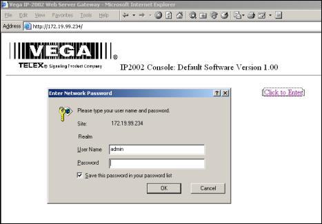
To begin setup of the IP-2002 console, the user must know the base IP address that was entered from the front panel. The address then entered into the browser is http://XXX.XXX.XXX.XXX, where the XXX’s refer to the values for the assigned IP address. Upon pressing return in the browser the opening screen should appear as shown in Figure 11.
Figure 11 IP-2002 Login Screen
Clicking on the hyperlink [Click to Enter] will open a dialog box requesting user authentication. There is only one user name defined. It is “admin”. If it is the first time the console as been started and no PIN number has been entered, no password will be required. If a PIN has been set, enter it into the password field. Once the username and password has been successfully entered, the opening web page for Basic Ethernet Setup will be displayed.
5.5.1Orange Crossover Cable
An orange crossover cable provides for direct PC to IP-2002 programming through the Ethernet port. This cable should not be used for a direct IP-2002 to Ethernet port connection.

10 |
Vega’s IP-2002 |
5.6 Basic Ethernet Setup
Figure 12 Basic Ethernet Setup Screen
The Basic Ethernet Setup Page is the default startup page when entering the setup mode, see Figure 12. Across the top of the page is a table 4x3 cells in dimension. Each of these text strings is a link to a different setup page. Clicking the mouse pointer on any of these will immediately load the page clicked on. Moving from one page to the next does not automatically save any data that has been entered. To make changes to a page and save it to memory requires that the “Submit” button at the bottom of each page be pressed. Submit has the effect of sending the contents of the web page back to the IP-2002 for storage.
The fields of the Basic Ethernet Setup page are as follows:
5.6.1Use DHCP Server:
The DHCP server check box is generally left unchecked. DHCP is the Dynamic Host Configuration Protocol. It allows the IP-2002 to require all of the information for operation on the network bypassing its manual entry. Vega does not recommend operating with DHCP on. It can cause the Base IP address to change unexpectedly making changing setup of software more difficult. It can be useful for initial setup efforts in determining some of the other parameters.
5.6.2Unit IP Address:
The Unit IP Address is the base address assigned to the IP-2002. It must be unique on the Network. It identifies the console for such operations as setup and software upgrades.
 Loading...