


 Loading...
Operating Instructions
VEGADIF 55
4 … 20 mA/HART
 p
p
Di erential pressure

Contents
Contents
1About this document
1.1 |
Function . . . . . . . . . . . . . . . . . . . . . . . . . . . . . . . . . |
4 |
1.2 |
Target group . . . . . . . . . . . . . . . . . . . . . . . . . . . . . . |
4 |
1.3 |
Symbolism used . . . . . . . . . . . . . . . . . . . . . . . . . . . |
4 |
2For your safety
2.1 |
Authorised personnel . . . . . . . . . . . . . . . . . . . . . . . . |
5 |
2.2 |
Appropriate use . . . . . . . . . . . . . . . . . . . . . . . . . . . . |
5 |
2.3 |
Warning about misuse . . . . . . . . . . . . . . . . . . . . . . . |
5 |
2.4 |
General safety instructions . . . . . . . . . . . . . . . . . . . . |
5 |
2.5 Safety approval markings and safety tips . . . . . . . . . |
6 |
|
2.6 Safety approval markings and safety tips . . . . . . . . . |
6 |
|
2.7 |
CE conformity . . . . . . . . . . . . . . . . . . . . . . . . . . . . . |
6 |
2.8 Safety instructions for Ex areas . . . . . . . . . . . . . . . . |
6 |
|
2.9 |
Environmental instructions . . . . . . . . . . . . . . . . . . . . |
6 |
3Product description
3.1 |
Configuration . . . . . . . . . . . . . . . . . . . . . . . . . . . . . . |
7 |
3.2 |
Principle of operation . . . . . . . . . . . . . . . . . . . . . . . . |
8 |
3.3 |
Operation . . . . . . . . . . . . . . . . . . . . . . . . . . . . . . . . |
9 |
3.4 |
Packaging, transport and storage . . . . . . . . . . . . . . . |
9 |
4Mounting
4.1 |
General instructions . . . . . . . . . . . . . . . . . . . . . . . . . |
11 |
4.2 Mounting instructions for flow measurement . . . . . . . |
12 |
|
4.3 Mounting instructions for level measurement . . . . . . . |
15 |
|
4.4 Mounting instructions with di erential pressure |
|
|
|
measurement . . . . . . . . . . . . . . . . . . . . . . . . . . . . . |
20 |
4.5 |
Mounting for instruments with isolating diaphragms . . |
21 |
4.6 Mounting instructions for seal with flange mounting . . |
24 |
|
4.7 Heat insulation of instruments with flange isolating |
|
|
|
diaphragm . . . . . . . . . . . . . . . . . . . . . . . . . . . . . . . . |
24 |
4.8 |
Mounting instructions for wall or tube mounting . . . . . |
26 |
4.9 |
Mounting control . . . . . . . . . . . . . . . . . . . . . . . . . . . |
26 |
5Connecting to power supply
5.1 |
Preparing the connection . . . . . . . . . . . . . . . . . . . . . |
27 |
5.2 |
Connection procedure . . . . . . . . . . . . . . . . . . . . . . . |
28 |
5.3 |
Wiring plan . . . . . . . . . . . . . . . . . . . . . . . . . . . . . . . |
28 |
5.4 Take 4 … 20 mA test signal . . . . . . . . . . . . . . . . . . . |
30 |
|
5.5 |
Load . . . . . . . . . . . . . . . . . . . . . . . . . . . . . . . . . . . . |
30 |
5.6 |
Connection control . . . . . . . . . . . . . . . . . . . . . . . . . |
30 |
5.7 |
Switch on phase . . . . . . . . . . . . . . . . . . . . . . . . . . . |
31 |
6Operation
6.1 Short description . . . . . . . . . . . . . . . . . . . . . . . . . . . 32 6.2 Local indication (optional) . . . . . . . . . . . . . . . . . . . . 32 6.3 Adjustment elements . . . . . . . . . . . . . . . . . . . . . . . . 35 6.4 Local adjustment - local indication not connected . . . 37
2 |
VEGADIF 55 • 4 … 20 mA/HART |
081119-EN-31731

31731-EN-081119
|
|
Contents |
6.5 |
Local adjustment - local indication connected . . |
. . . . 40 |
6.6 |
Data memory module (optional) . . . . . . . . . . . . . |
. . . 44 |
6.7 |
Copy configuration data . . . . . . . . . . . . . . . . . . . |
. . . 45 |
6.8 |
Adjustment via HART handheld . . . . . . . . . . . . . |
. . . 48 |
6.9 |
Lock/Unlock adjustment . . . . . . . . . . . . . . . . . . . |
. . . 48 |
6.10 |
Default setting (reset) . . . . . . . . . . . . . . . . . . . . |
. . . 49 |
6.11 |
Menu schematic . . . . . . . . . . . . . . . . . . . . . . . . |
. . . 52 |
7Set up
7.1 |
Warning instructions . . . . . . . . . . . . . . . . . . . . . . . . |
57 |
7.2 Installation and function control . . . . . . . . . . . . . . . . . |
57 |
|
7.3 Select language and measuring mode . . . . . . . . . . . |
57 |
|
7.4 |
Position correction . . . . . . . . . . . . . . . . . . . . . . . . . . |
58 |
7.5 |
Flow measurement . . . . . . . . . . . . . . . . . . . . . . . . . |
59 |
7.6 |
Level measurement . . . . . . . . . . . . . . . . . . . . . . . . . |
64 |
7.7 |
Di erential pressure measurement . . . . . . . . . . . . . . |
74 |
8Maintenance and fault rectification
8.1 |
Maintenance . . . . . . . . . . . . . . . . . . . . . . . . . . . . . . |
78 |
8.2 |
Remove interferences . . . . . . . . . . . . . . . . . . . . . . . |
78 |
8.3 |
Replacement parts . . . . . . . . . . . . . . . . . . . . . . . . . |
78 |
8.4 |
Instrument repair . . . . . . . . . . . . . . . . . . . . . . . . . . . |
79 |
9Dismounting
9.1 |
Dismounting steps . . . . . . . . . . . . . . . . . . . . . . . . . . |
80 |
9.2 |
Disposal . . . . . . . . . . . . . . . . . . . . . . . . . . . . . . . . . |
80 |
10 Supplement |
|
|
10.1 Technical data and dimensions . . . . . . . . . . . . . . . . |
81 |
|
Supplementary documentation
Information:
Supplementary documents appropriate to the ordered version come with the delivery. You can find them listed in chapter "Product
description".
VEGADIF 55 • 4 … 20 mA/HART |
3 |
1 About this document
1 About this document
1.1 Function
This operating instructions manual provides all the information you need for mounting, connection and setup as well as important instructions for maintenance and fault rectification. Please read this information before putting the instrument into operation and keep this manual accessible in the immediate vicinity of the device.
1.2 Target group
This operating instructions manual is directed to trained personnel. The contents of this manual should be made available to these personnel and put into practice by them.
1.3 Symbolism used
Information, tip, note
This symbol indicates helpful additional information.
Caution: If this warning is ignored, faults or malfunctions can result.
Warning: If this warning is ignored, injury to persons and/or serious damage to the instrument can result.
Danger: If this warning is ignored, serious injury to persons and/or destruction of the instrument can result.
Ex applications
This symbol indicates special instructions for Ex applications.
•List
The dot set in front indicates a list with no implied sequence.
àAction
This arrow indicates a single action.
1Sequence
Numbers set in front indicate successive steps in a procedure.
081119-EN-31731
4 |
VEGADIF 55 • 4 … 20 mA/HART |

31731-EN-081119
2 For your safety
2 For your safety
2.1 Authorised personnel
All operations described in this operating instructions manual must be carried out only by trained specialist personnel authorised by the plant operator.
During work on and with the device the required personal protection equipment must always be worn.
2.2 Appropriate use
VEGADIF 55 is a di erential pressure transmitter for measurement of flow, level or di erential pressure.
You can find detailed information on the application range in chapter
"Product description".
Operational reliability is ensured only if the instrument is properly used according to the specifications in the operating instructions manual as well as possible supplementary instructions.
For safety and warranty reasons, any invasive work on the device beyond that described in the operating instructions manual may be carried out only by personnel authorised by the manufacturer. Arbitrary conversions or modifications are explicitly forbidden.
2.3 Warning about misuse
Inappropriate or incorrect use of the instrument can give rise to application-specific hazards, e.g. vessel overfill or damage to system components through incorrect mounting or adjustment.
2.4 General safety instructions
This is a high-tech instrument requiring the strict observance of standard regulations and guidelines. The user must take note of the safety instructions in this operating instructions manual, the countryspecific installation standards as well as all prevailing safety regulations and accident prevention rules.
The instrument must only be operated in a technically flawless and reliable condition. The operator is responsible for trouble-free operation of the instrument.
During the entire duration of use, the user is obliged to determine the compliance of the required occupational safety measures with the current valid rules and regulations and also take note of new regulations.
VEGADIF 55 • 4 … 20 mA/HART |
5 |

2 For your safety
2.5 Safety approval markings and safety tips
The safety approval markings and safety tips on the device must be observed.
2.6 Safety approval markings and safety tips
The safety approval markings and safety tips on the device must be observed.
2.7 CE conformity
VEGADIF 55 is CE conform to EMVG (89/336/EWG), NSR (73/23/
EWG) and corresponds to NAMUR recommendation EMC (NE 21).
Conformity has been judged according to the following standards:
•EMC: Emission EN 61326 instrument B, susceptibility EN 61326 supplement A (industrial area)
•LVD: EN 61010-1
The instrument corresponds to article 3 (3) of EG directive 97/23/EG pressure device regulation and is designed according to good engineering experience. VEGADIF 55 as basic instrument with PN 420 withtout isolating diaphragm is suitable for stable gases of group 1, category 1.
2.8 Safety instructions for Ex areas
Please note the Ex-specific safety information for installation and operation in Ex areas. These safety instructions are part of the operating instructions manual and come with the Ex-approved instruments.
2.9 Environmental instructions
Protection of the environment is one of our most important duties. That is why we have introduced an environment management system with the goal of continuously improving company environmental protection. The environment management system is certified according to DIN EN ISO 14001.
Please help us fulfil this obligation by observing the environmental instructions in this manual:
•Chapter "Packaging, transport and storage"
•Chapter "Disposal"
081119-EN-31731
6 |
VEGADIF 55 • 4 … 20 mA/HART |
3 Product description
|
3 |
Product description |
|
3.1 Configuration |
|
Scope of delivery |
The scope of delivery encompasses: |
|
|
• VEGADIF 55 di erential pressure transmitter |
|
|
• Version with lateral flanges of 316L or C22.8: in addition 2 |
|
|
|
ventilation valves, 316L |
|
• Version with lateral flanges of 316L or C22.8 and lateral |
|
|
|
ventilations: in addition 4 closing screws, 316L |
|
• |
Optional accessory |
|
• |
Documentation |
|
|
- this operating instructions manual |
|
|
- Short instruction (in housing cover) |
|
|
- Final inspection protocol |
|
|
- Supplementary instructions manual - 31732 "Service instruc- |
|
|
tions for VEGADIF 55" |
|
|
- Ex-specific "Safety instructions" (with Ex-versions) |
|
|
- if necessary, further certificates |
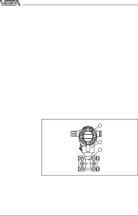
Components |
VEGADIF 55 consists of the following components: |
|
|
• Process fitting with measuring cell |
|
|
• Housing with electronics, optionally available with plug connector |
|
|
• Housing cover, optionally available with local indication |
|
|
The components are available in di erent versions. |
|
|
|
1 |
|
|
2 |
|
|
3 |
|
|
+ – |
31731-EN-081119
Fig. 1: VEGADIF 55 in basic version
1 Housing cover, optionally available with subjacent on-site indication
2Housing with electronics
3Process fitting with measuring cell
Type label |
The type label contains the most important data for identification and |
|
|
use of the instrument: |
|
|
• |
Article number |
|
• |
Serial number |
VEGADIF 55 • 4 … 20 mA/HART |
7 |
3 Product description
•Technical data
•Article numbers documentation
With the serial number, you can access the delivery data of the instrument via "www.vega.com", "VEGA Tools" and "serial number search". In addition to the type label outside, you can also find the serial number on the inside of the instrument.
Area of application
Functional principle
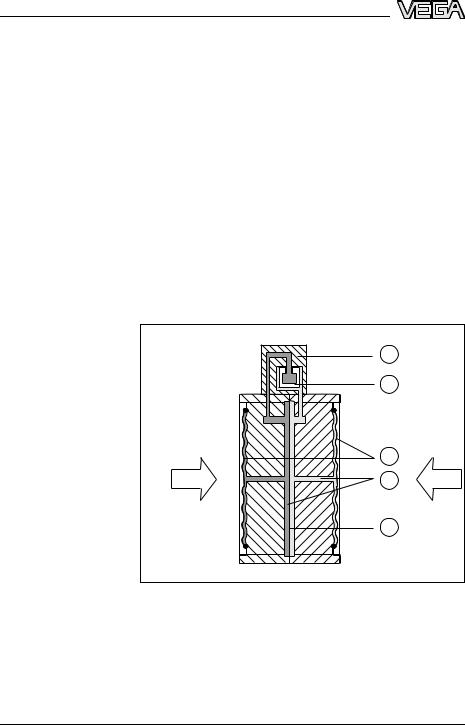
3.2 Principle of operation
VEGADIF 55 is a di erential pressure transmitter for measurement of flow, level or di erential pressure. Measured products are gases, vapours and liquids.
The sensor element is a metallic measuring cell. The process pressure is transmitted via the separating diaphragm and filling oil to the resistance measuring bridge (semi-conductor technology). The di er- ential-pressure dependent change of the bridge voltage is measured, further processed and converted into a corresponding output signal.
The configuration of the measuring cell di ers depending on the measuring range:
|
1 |
|
|
2 |
|
|
3 |
|
p1 |
4 |
p2 |
|
5 |
|
Fig. 2: Metal measuring cell 10 mbar and 30 mbar 1 Measuring element
2Silicone diaphragm
3 Separating diaphragm
4Filling oil
5Integrated overvoltage arrester
8 |
VEGADIF 55 • 4 … 20 mA/HART |
081119-EN-31731
31731-EN-081119
Voltage supply
Packaging
3 Product description
|
1 |
2 |
|
3 |
|
|
|
|
p1 |
|
p2 |
|
|
4 |
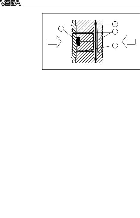
Fig. 3: Metal measuring cell from 100 mbar
1Measuring element
2 Overload diaphragm/Middle diaphragm
3Filling oil
4Separating diaphragm
Two-wire electronics 4 … 20 mA/HART for power supply and measured value transmission over the same cable.
The voltage supply range can di er depending on the instrument version. The exact range is stated in chapter "Wiring plan " or "Technical data" in the product information manual "VEGADIF 55".
3.3 Operation
VEGADIF 55 can be adjusted with di erent adjustment media:
•via integrated adjustment keys and local indication (available as options)
•an adjustment software according to FDT/DTM standard, e.g. PACTware and PC
•with manufacturer-specific adjustment programs AMS™ or PDM
•With a HART handheld
The entered parameters are generally saved in VEGADIF 55, optionally also in PACTware.
3.4 Packaging, transport and storage
Your instrument was protected by packaging during transport. Its capacity to handle normal loads during transport is assured by a test according to DIN EN 24180.
The packaging of standard instruments consists of environmentfriendly, recyclable cardboard. For special versions, PE foam or PE foil is also used. Dispose of the packaging material via specialised recycling companies.
VEGADIF 55 • 4 … 20 mA/HART |
9 |

3 Product description
Transport |
Transport must be carried out under consideration of the notes on the |
|
transport packaging. Nonobservance of these instructions can cause |
|
damage to the device. |
Transport inspection |
The delivery must be checked for completeness and possible transit |
|
damage immediately at receipt. Ascertained transit damage or |
|
concealed defects must be appropriately dealt with. |
Storage |
Up to the time of installation, the packages must be left closed and |
|
stored according to the orientation and storage markings on the |
|
outside. |
|
Unless otherwise indicated, the packages must be stored only under |
|
the following conditions: |
|
• Not in the open |
|
• Dry and dust free |
|
• Not exposed to corrosive media |
|
• Protected against solar radiation |
|
• Avoiding mechanical shock and vibration |
Storage and transport |
• Storage and transport temperature see chapter "Supplement - |
temperature |
Technical data - Ambient conditions" |
|
• Relative humidity 20 … 85 % |
081119-EN-31731
10 |
VEGADIF 55 • 4 … 20 mA/HART |
|
|
|
4 Mounting |
|
|
4 |
Mounting |
|
|
4.1 |
General instructions |
Materials, wetted parts |
Make sure that the wetted parts of VEGADIF 55, especially the seal |
||
|
|
and process fitting, are suitable for the existing process conditions |
|
|
|
such as pressure, temperature etc. as well as the chemical properties |
|
|
|
of the medium. |
|
|
|
You find the specification in the "Product information manual" |
|
|
|
VEGADIF 55 in chapter "Technical data". |
|
Mounting position |
Select such a mounting position that the instrument is in easy reach |
||
|
|
when mounting or connecting as well as for later retrofitting of the |
|
indicating and adjustment module. After loosening the pin, the housing can be rotated by 380°.
Proceed as follows:
1 Loosen the pin with a 2 mm Allen wrench 2 Rotate the housing (max. up to 380°)
3 Tighten the pin
 max. 380°
31731-EN-081119
Fig. 4: Direct the housing
Installation position Due to the installation position of VEGADIF 55, a zero point shifting can be caused, i.e. the measured values is not zero with empty vessel. You can correct this zero point shoft either directly on the instrument via the "E" key or the remote adjustment, see chapter "Operating
elements" and "Position adjustment".
E ective pressure lines You find general recommendations for wiring of e ective pressure lines in DIN 19210 "E ective pressure lines for flow systems" or the corresponding national or international standards. When wiring e ective pressure lines outdoors, keep in mind to use a suitable antifreeze, e.g. by using tube heat tracing. Wire e ective pressure lines with a monotonic decrease of at least 10 %.
Valve block |
Using a three-fold or five-fold valve block ensures easy setup, |
|
|
mounting and maintenance without interrupting the process. |
|
|
|
|
VEGADIF 55 |
• 4 … 20 mA/HART |
11 |
4 Mounting
Oxygen applications
Danger:
Instruments for oxygen applications should be unpacked just before mounting. After removing the protective cover of the process fitting, the label "O " will be visible on the process fitting. Penetration of oil, grease and dirt should be avoided. Danger of explosion!
Moisture |
Use the recommended cables (see chapter "Connecting to power |
|
supply") and tighten the cable gland. |
|
You can give your VEGADIF 55 additional protection against moisture |
|
penetration by leading the connection cable downward in front of the |
|
cable entry. Rain and condensation water can thus drain o . This |
|
applies mainly to outdoor mounting as well as installation in areas |
|
where high humidity is expected (e.g. through cleaning processes) or |
|
on cooled or heated vessels. |
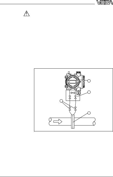
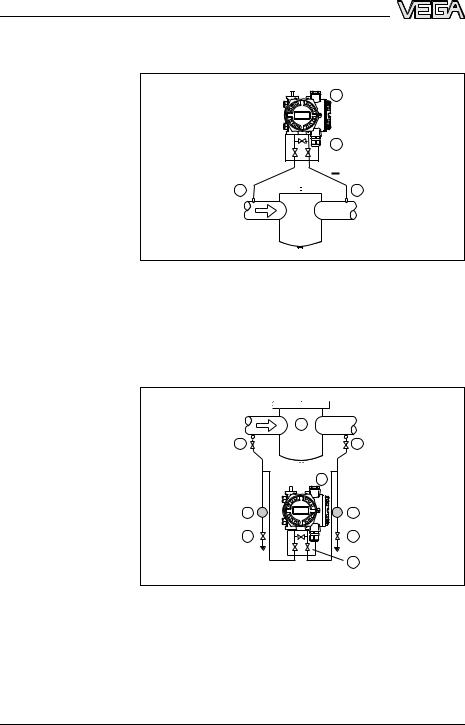
4.2 Mounting instructions for flow measurement
Flow measurement in |
|
|
gases |
|
|
|
|
1 |
|
|
2 |
3 |
|
|
+ |
– |
4 |
Fig. 5: Measurement setup, flow measurement in gases with VEGADIF 55
1VEGADIF 55
2 Three-fold valve block
3Block valves
4Orifice or impact pressure probe
àMount VEGADIF 55 above the measurement loop so that condensate can drain o in the process cable.
12 |
VEGADIF 55 • 4 … 20 mA/HART |
081119-EN-31731
4 Mounting
Flow measurement in |
1 |
||
vapours |
|||
|
|
||
|
|
|
|
|
2 |
|
3 |
|
3 |
+ |
4 |
– |
|
||
5 |
|
5 |
6 |
|
6 |
|
|
7 |
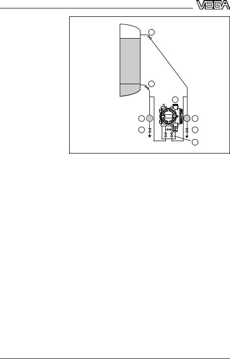
Fig. 6: Measurement setup, flow measurement in vapours with VEGADIF 55
1Condensate vessels
2 Orifice or impact pressure probe
3 Block valves
4VEGADIF 55
5 Precipitator
6Drain valves
7Three-fold valve block
àMount VEGADIF 55 below the measurement loop
àMount condensate vessels at the same height with the discharge socket and at the same distance to VEGADIF 55
àFill the e ective pressure lines to the height of the condensate vessels before setup
31731-EN-081119
VEGADIF 55 • 4 … 20 mA/HART |
13 |
4 Mounting
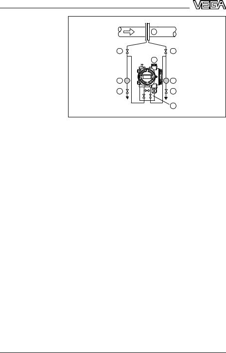
Flow measurement in liquids
|
1 |
|
2 |
|
2 |
+ |
3 |
– |
|
||
4 |
|
4 |
5 |
|
5 |
|
|
6 |
Fig. 7: Measurement setup, flow measurement in liquids with VEGADIF 55 1 Orifice or impact pressure probe
2 Block valves
3VEGADIF 55
4 Precipitator
5Drain valves
6Three-fold valve block
àMount VEGADIF 55 below the measurement loop so that the e ective pressure lines are always filled with liquid and gas bubbles can bubble up to the process line
àFor measurements in products with solid content such as e.g. dirty liquids, the installation of separators and drain valves is recommended to enable collection and removal of debris and sediment.
àFill the e ective pressure lines to the height of the condensate vessels before setup
081119-EN-31731
14 |
VEGADIF 55 • 4 … 20 mA/HART |
31731-EN-081119
4 Mounting
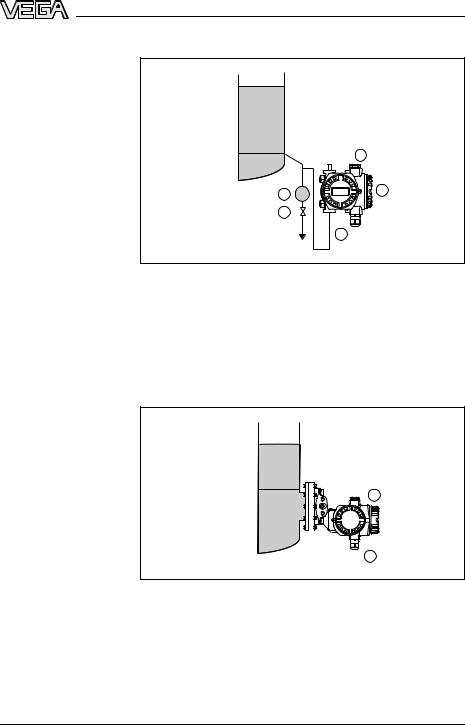
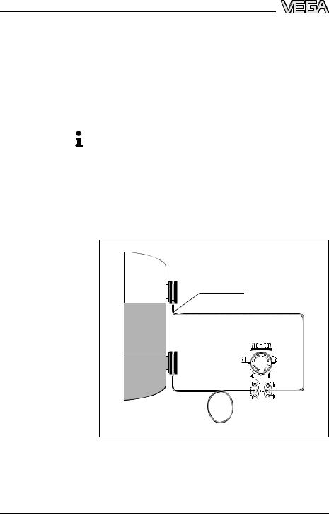
Level measurement in the open vessel with e ective pressure line
4.3 Mounting instructions for level measurement
patm
min. + patm 1
4 |
2 |
|
5
 3
3
Level measurement in the open vessel with flange
Fig. 8: Measurement setup, level measurement in the open vessel 1 Minus side is open to the atmospheric pressure
2 VEGADIF 55
3Block valve
4 Precipitator
5Drain valve
àMount VEGADIF 55 below the lower measurement connection so that the e ective pressure lines are always filled with liquid
àMinus side is open to the atmospheric pressure
patm
min.
1
– 
patm 2
Fig. 9: Measurement setup, level measurement in the open vessel
1VEGADIF 55
2Minus side is open to the atmospheric pressure
àMount VEGADIF 55 directly to the vessel
àMinus side is open to the atmospheric pressure
VEGADIF 55 • 4 … 20 mA/HART |
15 |
4 Mounting
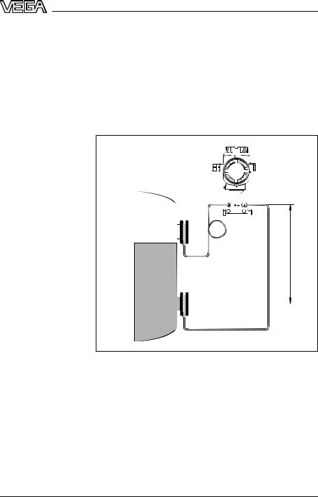
Level measurement in |
|
|
|
closed vessel with ef- |
– |
1 |
|
fective pressure line |
|||
max. |
|
||
|
|
min. 1
+ |
|
|
2 |
3 |
3 |
4 |
4 |
|
5 |
Fig. 10: Measurement setup, level measurement in closed vessel 1 Block valves
2VEGADIF 55
3 Precipitator
4Drain valves
5Three-fold valve block
àMount VEGADIF 55 below the lower measurement connection so that the e ective pressure lines are always filled with liquid
àConnect minus side always above the max. level
àFor measurements in products with solid content such as e.g. dirty liquids, the installation of separators and drain valves is recommended to enable collection and removal of debris and sediment.
081119-EN-31731
16 |
VEGADIF 55 • 4 … 20 mA/HART |
4 Mounting
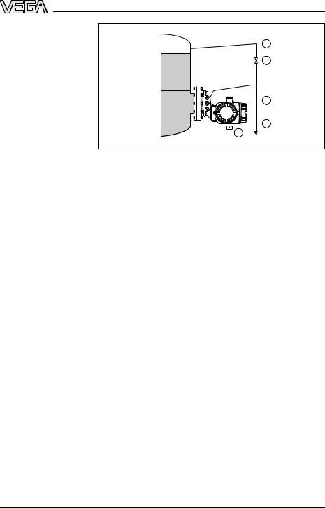
Level measurement in |
1 |
|
closed vessel with |
||
|
||
flange |
max. |
|
|
||
|
min. |
|
|
2 |

 3 4
3 4 
Level measurement in closed vessel with cell isolating diaphragms
Fig. 11: Measurement setup, level measurement in closed vessel
1Block valve
2 |
Precipitator |
3 |
Drain valve |
4VEGADIF 55
àMount VEGADIF 55 directly to the vessel
àConnect minus side always above the max. level
àFor measurements in products with solid content such as e.g. dirty liquids, the installation of separators and drain valves is recommended to enable collection and removal of debris and sediment.
–
max.
1
min.
31731-EN-081119
Fig. 12: Measurement setup, level measurement in closed vessel
1VEGADIF 55
àMount VEGADIF 55 below the lower isolating diaphragm
àThe ambient temperature should be the same for both capillaries
VEGADIF 55 • 4 … 20 mA/HART |
17 |
4 Mounting
Information:
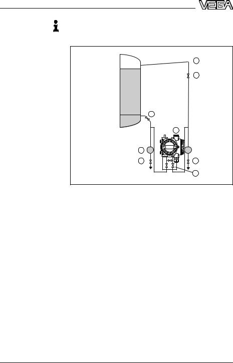
Level measurement in closed vessel with steam layer with e ective pressure line
Level measurement is only ensured between the upper edge of the lower and the lower edge of the upper pressure transmitter.
– 1
1
max.
2
min. |
+ 2 |
|
3 |
4 |
|
5 |
5 |
|
6 |
Fig. 13: Measurement setup in closed vessel with superimposed steam 1 Condensate vessel
2 Block valves
3VEGADIF 55
4 Precipitator
5Drain valves
6Three-fold valve block
àMount VEGADIF 55 below the lower measurement connection so that the e ective pressure lines are always filled with liquid
àConnect minus side always above the max. level
àThe condensate vessel ensures a constant pressure on the minus side
àFor measurements in products with solid content such as e.g. dirty liquids, the installation of separators and drain valves is recommended to enable collection and removal of debris and sediment.
081119-EN-31731
18 |
VEGADIF 55 • 4 … 20 mA/HART |
Level measurement in closed vessel with superimposed steam with flange
4 Mounting
– 1
1
max.
2
min.
 3
3
+ 


 4
4
 5
5
Fig. 14: Measurement setup in closed vessel with superimposed steam 1 Condensate vessel
2Block valve
3 |
Precipitator |
4 |
Drain valve |
5VEGADIF 55
àMount VEGADIF 55 directly to the vessel
àConnect minus side always above the max. level
àThe condensate vessel ensures a constant pressure on the minus side
àFor measurements in products with solid content such as e.g. dirty liquids, the installation of separators and drain valves is recommended to enable collection and removal of debris and sediment.
31731-EN-081119
VEGADIF 55 • 4 … 20 mA/HART |
19 |
4 Mounting
4.4 Mounting instructions with di erential pressure measurement
Di erential pressure |
|
measurement in gases |
1 |
and vapours |
|
2
+
3 

 3
3
Di erential pressure measurement in liquids
Fig. 15: Measurement setup, di erential pressure measurement in gases and vapours with VEGADIF 55
1VEGADIF 55
2 Three-fold valve block
3 Block valves
4E.g. filter
àMount VEGADIF 55 above the measurement loop so that condensate can drain o in the process cable.
1
2 |
2 |
+  –
–
|
3 |
4 |
4 |
5 |
5 |
|
6 |
Fig. 16: Measurement setup, flow measurement in liquids with VEGADIF 55
1E.g. filter
2 Block valves
3VEGADIF 55
4 Precipitator
5Drain valves
6Three-fold valve block
20 |
VEGADIF 55 • 4 … 20 mA/HART |
081119-EN-31731
4 Mounting
àMount VEGADIF 55 below the measurement loop so that the e ective pressure lines are always filled with liquid and gas bubbles can bubble up to the process line
àFor measurements in products with solid content such as e.g. dirty liquids, the installation of separators and drain valves is recommended to enable collection and removal of debris and sediment.
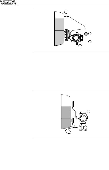
Di erential pressure |
|
1 |
measurement in gases, |
|
|
vapours and liquids |
2 |
2 |
+  –
–
3
4
31731-EN-081119
Fig. 17: Measurement setup, di erential pressure measurement in gases, vapours and liquids with VEGADIF 55
1Cell isolating diaphragm
2Capillaries
3E.g. filter
4VEGADIF 55
àMount isolating diaphragm with capillaries on top or laterally on the pipeline
àIn vacuum applications: Mount VEGADIF 55 below the measurement loop
àThe ambient temperature should be the same for both capillaries
4.5 Mounting for instruments with isolating diaphragms
Isolating diaphragm
Note these general instructions to the isolating diaphragms:
Note:
• An isolating diaphragm together with a pressure transmitter forms a closed, calibrated system which is filled through openings in the isolating diaphragm and the measuring element of the pressure transmitter. These openings are sealed and must not be opened!
•Do not clean or touch the isolating diaphragm with hard or sharp subjects
•Remove the diaphragm protection just before installation
•When using a mounting strap, there must be su cient strain relief for the capillaries to avoid bending them (bending radius ≥ 100 mm)
VEGADIF 55 • 4 … 20 mA/HART |
21 |
4 Mounting
•Remember that due to the hydrostatic pressure of the liquid columns in the capillaries, a zero point shift can occur. The zero point shift can be corrected, see also "Position adjustment".
•Keep the application limits of the isolating diaphragm filling oil in mind according to the Product Information manual VEGADIF 55,
"Planning instructions isolating diaphragms"
Capillaries
To achieve more precise measuring results and avoid instrument malfunctions, the capillaries must be mounted as follows:
Note:
• Vibration-free (to avoid additional pressure fluctuations)
•Not close to heating or cooling lines
•Insulate them in cooler or warmer environment
•Lay wire with a bend radius ≥ 100 mm
•With isolating diaphragms on both sides, the ambient temperature and length of both capillaries should be the same
•Always two identical isolating diaphragms (e.g. diameter, material etc.) should be used for the minus and plus side (standard shipment)
–
≥ 100 mm
Fig. 18: Mounting VEGADIF 55 with isolating diaphragms and capillaries with vacuum application: place the pressure transmitter below the lower isolating diaphragm
22 |
VEGADIF 55 • 4 … 20 mA/HART |
081119-EN-31731
4 Mounting
Vacuum application
In applications under vacuum, we recommend mounting the pressure transmitter below the lower isolating diaphragm. A vacuum load on the isolating diaphragm due to the filling oil in the capillaries is thus avoided.
When mounting the pressure transmitter above the lower isolating diaphragm, the max. di erence in height H1 must not be exceeded according to the following illustrations. The max. di erence in height depends on the density of the filling oil and the smallest pressure which can occur on the plus side of teh isolating diaphragm (empty vessel), see following illustration.
– 


 +
+
Fig. 19: Mounting above the lower isolating diaphragm
31731-EN-081119
VEGADIF 55 • 4 … 20 mA/HART |
23 |

4 Mounting
m |
|
|
|
|
|
|
|
|
|
|
12,0 |
|
|
|
|
|
|
|
|
|
|
|
|
|
|
|
|
|
1 |
|
|
|
10,0 |
|
|
|
|
|
2 |
|
|
|
|
|
|
|
|
|
|
|
|
|
|
|
8,0 |
|
|
|
|
|
|
|
|
|
|
6,0 |
|
|
|
|
|
|
3 |
|
|
|
|
|
|
|
|
|
|
|
|
|
|
4,0 |
|
|
|
|
|
|
|
|
|
|
|
|
|
|
|
|
|
4 |
|
|
|
2,0 |
|
|
|
|
|
|
|
|
|
|
0,0 |
|
|
|
|
|
|
|
|
|
mbar |
50 100 |
200 |
300 |
400 |
500 |
600 |
700 |
800 |
900 |
1000 |
Fig. 20: Diagram max. mounting height above the lower isolating diaphragm in vacuum applications depending on the pressure on the isolating diaphragm on the plus side
1 Vegetable oil
2Silicone oil
3 High temperature oil
4Inert oil
4.6 Mounting instructions for seal with flange mounting
1 |
2 |
Fig. 21: Mounting the versions with flange or isolating diaphragm 1 Diaphragm
2Seal
4.7 Heat insulation of instruments with flange isolating diaphragm
VEGADIF 55 with unilateral flange isolating diaphragm must only be isolated up to a certain height. The max. permissible isolating heigth is marked on the instruments and applies to an isolating material with a heat conductance ≤ 0.04 W/(m x K) and fa max. permitted ambient
24 |
VEGADIF 55 • 4 … 20 mA/HART |
081119-EN-31731

|
4 |
Mounting |
temperature TU ≤ 70 °C (158 °F) and process temperature TP < 350 °C |
||
(662 °F). The data were determined under the critical application |
||
"resting air". |
|
|
TA |
|
W |
|
λ ≤ 0,04 m•K |
|
|
TP |
|
Fig. 22: Max. permissible isolating height |
|
|
31731-EN-081119
VEGADIF 55 • 4 … 20 mA/HART |
25 |
4 Mounting
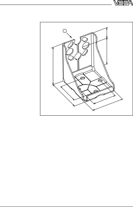
4.8 Mounting instructions for wall or tube mounting
1 |
37,5 |
|
|
|
97,5 |
135 |
|
74 |
|
124 |
|
|
74 |
|
106 |
Fig. 23: Mounting strap for wall or tube mounting
Take note of the following when mounting:
•Instruments with capillary lines: Mount capillaries with a bending radius of ≥ 100 mm
•Slightly grease the mounting screws so that the threaded connetion remains detachable
•For tube mounting, tighten the nuts on the strap with a torque of at least 30 Nm
4.9 Mounting control
Check the following after mounting the instrument:
•Did you tighten all screws?
•Housing cover tightened?
•Did you tighten the closing screws and the ventilation valves?
081119-EN-31731
26 |
VEGADIF 55 • 4 … 20 mA/HART |
Loading...