


FLEX61
Table of contents
 Loading...
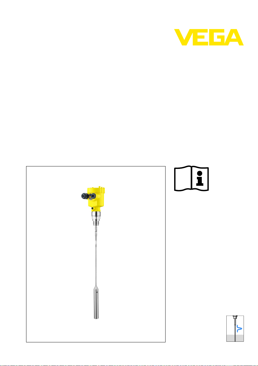
Ope
rating Instructions
VEGAFLEX 61
4 … 20 mA/HART two-wire
Document ID:
31833
uided Microwave
G

Contents
Conten
1 About this document
2 For your safety
3 Product description
4 Mounting
5 Connecting to power supply
ts
1.1 Function. . . . . . . . . . . . . . . . . . . . . . . . . . . . . . . . . .
1.2 Target group . . . . . . . . . . . . . . . . . . . . . . . . . . . . . .
1.3 Symbolism used. . . . . . . . . . . . . . . . . . . . . . . . . . . .
2.1 Authorised personnel . . . . . . . . . . . . . . . . . . . . . . . .
2.2 Appropriate use . . . . . . . . . . . . . . . . . . . . . . . . . . . .
2.3 Warning about misuse . . . . . . . . . . . . . . . . . . . . . . .
2.4 General safety instructions . . . . . . . . . . . . . . . . . . . .
2.5 Safety label on the instrument . . . . . . . . . . . . . . . . . .
2.6 CE conformity . . . . . . . . . . . . . . . . . . . . . . . . . . . . .
2.7 Fulfillment of NAMUR recommendations . . . . . . . . . .
2.8 Safety instructions for Ex areas . . . . . . . . . . . . . . . . .
2.9 Environmental instructions. . . . . . . . . . . . . . . . . . . . .
3.1 Structure . . . . . . . . . . . . . . . . . . . . . . . . . . . . . . . . .
3.2 Principle of operation . . . . . . . . . . . . . . . . . . . . . . . .
3.3 Operation. . . . . . . . . . . . . . . . . . . . . . . . . . . . . . . . .
3.4 Packaging, transport and storage . . . . . . . . . . . . . . .
4.1 General instructions . . . . . . . . . . . . . . . . . . . . . . . . .
4.2 Mounting instructions . . . . . . . . . . . . . . . . . . . . . . . .
5.1 Preparing the connection . . . . . . . . . . . . . . . . . . . . .
5.2 Connection procedure. . . . . . . . . . . . . . . . . . . . . . . .
5.3 Wiring plan, single chamber housing . . . . . . . . . . . . .
5.4 Wiring plan, double chamber housing . . . . . . . . . . . .
5.5 Wiring plan with double chamber housing Ex d . . . . .
5.6 Wiring plan - version IP 66/IP 68, 1 bar . . . . . . . . . . .
4
4
4
5
5
5
5
6
6
6
6
6
7
8
9
9
11
12
18
19
20
21
23
25
6 Set up with the indicating and adjustment module PLICSCOM
6.1 Short description . . . . . . . . . . . . . . . . . . . . . . . . . . .
6.2 Insert indicating and adjustment module. . . . . . . . . . .
6.3 Adjustment system . . . . . . . . . . . . . . . . . . . . . . . . . .
6.4 Setup steps . . . . . . . . . . . . . . . . . . . . . . . . . . . . . . .
6.5 Menu schematic. . . . . . . . . . . . . . . . . . . . . . . . . . . .
6.6 Saving the parameter adjustment data . . . . . . . . . . . .
7 Set up with PACTware and other adjustment programs
7.1 Connecting the PC . . . . . . . . . . . . . . . . . . . . . . . . . .
7.2 Parameter adjustment with PACTware. . . . . . . . . . . .
7.3 Parameter adjustment with AMS™ and PDM . . . . . . .
7.4 Saving the parameter adjustment data . . . . . . . . . . . .
2 VE
26
26
28
29
35
37
31833-EN-100426
38
39
40
40
GAFLEX 61 • 4 … 20 mA/HART two-wire
Contents
8 Maint
enance and fault rectification
8.1 Maintenance . . . . . . . . . . . . . . . . . . . . . . . . . . . . . .
8.2 Rectify malfunctions . . . . . . . . . . . . . . . . . . . . . . . . .
8.3 Exchange or shorten cable/rod . . . . . . . . . . . . . . . . .
8.4 Exchanging the electronics module . . . . . . . . . . . . . .
8.5 Software update. . . . . . . . . . . . . . . . . . . . . . . . . . . .
8.6 Instrument repair . . . . . . . . . . . . . . . . . . . . . . . . . . .
9 Dismounting
9.1 Dismounting steps . . . . . . . . . . . . . . . . . . . . . . . . . .
9.2 Disposal . . . . . . . . . . . . . . . . . . . . . . . . . . . . . . . . .
10 Supplement
10.1 Technical data . . . . . . . . . . . . . . . . . . . . . . . . . . . . .
10.2 Dimensions . . . . . . . . . . . . . . . . . . . . . . . . . . . . . . .
41
41
43
44
45
46
47
47
48
59
31833-EN-100426
VEGAFLEX 61 • 4 … 20 mA/HAR
Supplementary documentation
tion:
Informa
Supplementary documents a ppropriate to the ordered version come
with the delivery. You can find them listed in chapter "Product
description".
Instructions manuals for accessories and replacement parts
p:
Ti
To ensure reliable setup and operation of your VEGAFLEX 61, we
offer accessories and replacement parts. The corresponding documentations are:
l 27720 - VEGADIS 61
l 30207 - Electronics module VEGAFLEX series 60
l 34296 - Protective cover
l 31088 - Flanges according to DIN-EN-ASME-JIS-GOST
l 30391 - Spacer
T two-wire 3
1 Abou
t this document
1 Abou
t this document
1.1 Function
This operating instructions manual provides all the information you
need for mounting, connection and setup as well as important
instructions for maintenance and fault rectification. Please read this
information before putting the instrument into operation and keep this
manual accessible in the immediate vicinity of the device.
1.2 Target group
This operating instructions manual is directed to trained qualified
personnel. The contents of this manual should be made available to
these personnel and put into practice by them.
1.3 Symbolism used
Inform
ation, tip, note
This symbol indicates helpful additional information.
Cauti
on: If this warning is ignored, faults or malfunctions can
result.
Warning: If this warning is ignored, injury to persons and/or serious
damage to the instrument can result.
Danger: If this warning is ignored, serious injury to persons and/or
destruction of the instrument can result.
applications
Ex
This symbol indicates special instructions for Ex applications.
l List
The dot set in front indicates a list with no implied sequence.
à Action
Th
is arrow indicates a single action.
1 Sequence
Numbers set in front indicate successive steps in a procedure.
4 VE
31833-EN-100426
GAFLEX 61 • 4 … 20 mA/HART two-wire

your safety
2 For
or your safety
2 F
2.1 Authorised personnel
All operations described in this operating instructions manual must be
carried out only by trained specialist personnel authorised by the plant
operator.
During work on and with the device the required personal protective
equipment must always be worn.
2.2 Appropriate use
VEGAFLEX 61 is a sensor for continuous level measurement.
You can find detailed information on the application range in chapter
"Product description".
Operational reliability is ensured only if the instrument is properly used
according to the specifications in the operating instructions manual as
well as possible supplementary instructions.
For safety and warranty reasons, any invasive work on the device
beyond that described in the operating instructions manual may be
carried out only by personnel authorised by the manufacturer. Arbitrary
conversions or modifications are explicitly forbidden.
2.3 Warning about misuse
Inappropriate or incorrect use of the instrument can give rise to
application-specific hazards, e.g. vessel overfill or damage to system
components through incorrect mounting or adjustment.
31833-EN-100426
VEGAFLEX 61 • 4 … 20 mA/HAR
2.4 General safety instructions
This is a high-tech instrument requiring the strict observance of
standard regulations and guidelines. The user must take note of the
safety instructions in this operating instructions manual, the countryspecific installation standards as well as all prevailing safety
regulations and accident prevention rules.
The instrument must only be operated in a technically flawless and
reliable condition. The operator is responsible for trouble-free
operation of the instrument.
During the entire duration of use, the user is obliged to determine the
compliance of the required occupational safety measures with the
current valid rules and regulations and also take note of new
regulations.
T two-wire 5

2 For
your safety
2.5 Safety
The safety approval markings and safety tips on the device must be
observed.
label on the instrument
2.6 CE conformity
This device fulfills the legal requirements of the applicable EC
guidelines. By attaching the CE mark, VEGA provides a confirmation
of successful testing. You can find the CE conformity declaration in the
download area of
2.7 Fulfillmen
With respect to compatibility, the NAMUR recommendation NE 53 is
fulfilled. This applies also to the corresponding indicating and
adjustment components. VEGA instruments are generally upward and
downward compatible.
l Sensor software to DTM VEGAFLEX 61
l DTM VEGAFLEX 61 for adjustment software PACTware
l Indicating and adjustment module for sensor software
The parameter adjustment of the basic sensor functions is independent of the software version. The range of available functions depends
on the respective software version of the individual components.
www.vega.com.
t of NAMUR recommendations
2.8 Safety instructions for Ex areas
Please note the Ex-specific safety information for installation and
operation in Ex areas. These safety instructions are part of the
operating instructions manual and come with the Ex-approved
instruments.
2.9 Environmental instructions
Protection of the environment is one of our most important duties. That
is why we have introduced an environment management system with
the goal of continuously improving company environmental protection.
The environment management system is certified according to DIN
EN ISO 14001.
Please help us fulfil this obligation by observing the environmental
instructions in this manual:
l Chapter "Packaging, transport and storage"
l Chapter "Disposal"
6 VE
31833-EN-100426
GAFLEX 61 • 4 … 20 mA/HART two-wire

3 Produc
t description
Scope of delivery
Constituent parts
3 Produc
t description
3.1 Structure
The scope of delivery encompasses:
l VEGAFLEX 61 level sensor
l Documentation
- this operating instructions manual
- Safety Manual 31339 "VEGAFLEX series 60 - 4 … 20 mA/
HART" (optionally)
- Operating instructions manual 27835 "Indicating and adjust-
ment module PLICSCOM" (optional)
- Supplementary instructions manual 31708 "Heating for in-
dicating and adjustment module" (optional)
- Supplementary instructions manual "Plug connector for con-
tinuously measuring sensors" (optional)
- Ex-specific "Safety instructions" (with Ex versions)
- if necessary, further certificates
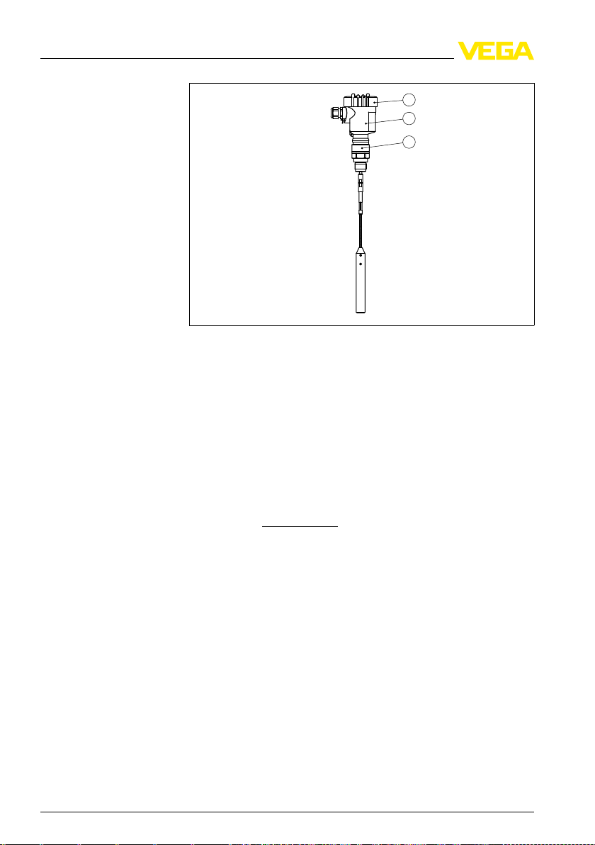
The VEGAFLEX 61 consists of the components:
l Process fitting with probe
l Housing with electronics
l Housing cover, optionally available with indicating and adjustment
module
31833-EN-100426
VEGAFLEX 61 • 4 … 20 mA/HAR
T two-wire 7
1
2
3
3 Produc
t description
Type label
Application area
Functional principle
Fig. 1: VEGAFLEX 61 in
1 Housing cover with integrated indicating and adjustment module (optional)
2 Housing with electronics
3 Process fitting
cable version with plastic housing
The type label contains the most important data for identification and
use of the instrument:
l Article number
l Serial number
l Technical data
l Article numbers, documentation
l SIL identification (with SIL rating ex works)
With the serial number, you can access the delivery data of the
instrument via
www.vega.com, "VEG
A Tools" and "serial number
search". In addition to the type label outside, you can also find the
serial number on the inside of the instrument.
3.2 Principle of operation
VEGAFLEX 61 is a level sensor with cable or rod probe for continuous
level measurement.
It is designed for industrial use in all areas of process technology and
can be used equally well in liquids or solids.
High frequency microwave pulses are guided along a steel rope or a
rod. Upon reaching the product surface, the microwave pulses are
reflected. The running time is evaluated by the instrument and
outputted as distance.
31833-EN-100426
Voltage supply
Two-wire electronics 4 … 20 mA/HART for power supply and
measured value transmission over the same cable.
8 VE
GAFLEX 61 • 4 … 20 mA/HART two-wire

3 Produc
e supply voltage range can differ depending on the instrument
Th
t description
version.
The data for power supply are specified in chapter "Technical data".
The optional background lighting of the indicating and adjustment
module is powered by the sensor. A certain level of operating voltage
is required for this. You can find the exact voltage specifications in
chapter "Technical data".
The optional heating requires its own operating voltage. You can find
details in the supplementary instructions manual "Heating for indicat-
ing and adjustment module".
This function is generally not available for approved instruments.
3.3 Operation
VEGAFLEX 61 can be adjusted with different adjustment media:
l with indicating and adjustment module
l with the suitable VEGA DTM in conjunction with an adjustment
software according to the FDT/DTM standard, e.g. PACTware and
PC
l with manufacturer-specific adjustment programs AMS™ or PDM
l With a HART handheld
3.4 Packaging, transport and storage
Packaging
Transport
Transport inspection
Storage
31833-EN-100426
VEGAFLEX 61 • 4 … 20 mA/HAR
Your instrument was protected by packaging during transport. Its
capacity to handle normal loads during transport is assured by a test
according to DIN EN 24180.
The packaging of standard instruments consists of environmentfriendly, recyclable cardboard. For special versions, PE foam or PE foil
is also used. Dispose of the packaging material via specialised
recycling companies.
Transport must be carried out under consideration of the notes on the
transport packaging. Nonobservance of these instructions can cause
damage to the device.
The delivery must be checked for completeness and possible transit
damage immediately at receipt. Ascertained transit damage or
concealed defects must be appropriately dealt with.
Up to the time of installation, the packages must be left closed and
stored according to the orientation and storage markings on the
outside.
Unless otherwise indicated, the packages must be stored only under
the following conditions:
l Not in the open
T two-wire 9

3 Produc
t description
Storage and transport
temperature
and dust free
l Dry
l Not exposed to corrosive media
l Protected against solar radiation
l Avoiding mechanical shock and vibration
l Storage and transport temperature see chapter "Supplement -
Technical data - Ambient conditions"
l Relative humidity 20 … 85 %
10 VE
31833-EN-100426
GAFLEX 61 • 4 … 20 mA/HART two-wire

4 M
ounting
Suitability for the process conditions
Mounting position
Welding work
Handling
4 Moun
ting
4.1 General instructions
Make sure that all parts of the instrument exposed to the process, in
particular the sensor element, process seal and process fitting, are
suitable for the existing process conditions. These include above all
the process pressure, process temperature as well as the chemical
properties of the medium.
You can find the specifications in chapter "Technical data" or on the
type label.
Select an installation position you can easily reach for mounting and
connecting as well as later retrofitting of an indicating and adjustment
module. The housing can be rotated by 330° without the use of any
tools. You can also install the indicating and adjustment module in four
different positions (each displaced by 90°).
Before beginning the welding work, remove the electronics module
from the sensor. By doing this, you avoid damage to the electronics
through inductive coupling.
With threaded versions, the housing must not be used to screw in the
instrument! Applying tightening forces on the housing can damage its
internal parts.
Use the hexagon for screwing in.
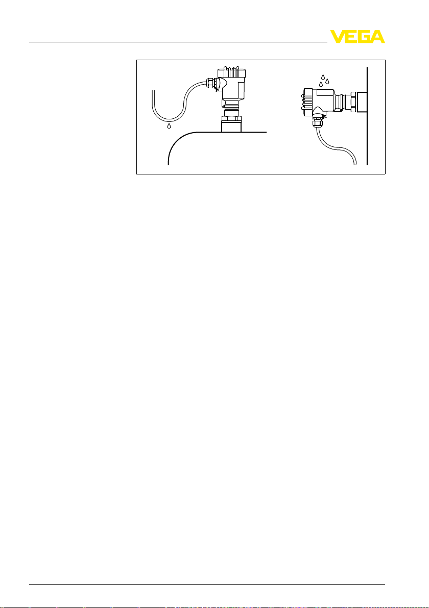
Moisture
31833-EN-100426
VEGAFLEX 61 • 4 … 20 mA/HAR
Use the recommended cables (see chapter "Connecting to power
supply") and tighten the cable gland.
You can give your instrument additional protection against moisture
penetration by leading the connection cable downward in front of the
cable entry. Rain and condensation water can thus drain off. This
applies mainly to outdoor mounting as well as installation in areas
where high humidity is expected (e.g. through cleaning processes) or
on cooled or heated vessels.
T two-wire 11
4 M
ounting
Measuring range
Pressure
Mounting position
Fig. 2: Measures
The reference plane for the measuring range of the sensors is the
sealing surface of the thread or flange.
Keep in mind that a min. distance must be maintained below the
reference plane and possibly also at the end of the probe measurement in these areas is not possible (dead band). Keep in mind
that the cable length cannot be used all the way to the end because
measurement in the area of the gravity weight is not possible. These
dead bands are listed in chapter "Technical data". Keep in mind for the
adjustment that the default setting for the measuring range refers to
water.
The process fitting must be sealed if there is gauge or low pressure in
the vessel. Before use, check if the seal material is resistant against
the measured product and the process temperature.
The max. permissible pressure is specified in chapter "Technical data"
or on the type label of the sensor.
against moisture penetration
4.2 Mounting instructions
Mount VEGAFLEX 61 in such a way that the distance to vessel
installations or to the vessel wall is at least 300 mm (12 in).
During operation, the probe must not touch any installations or the
vessel wall. If necessary, fasten the probe end.
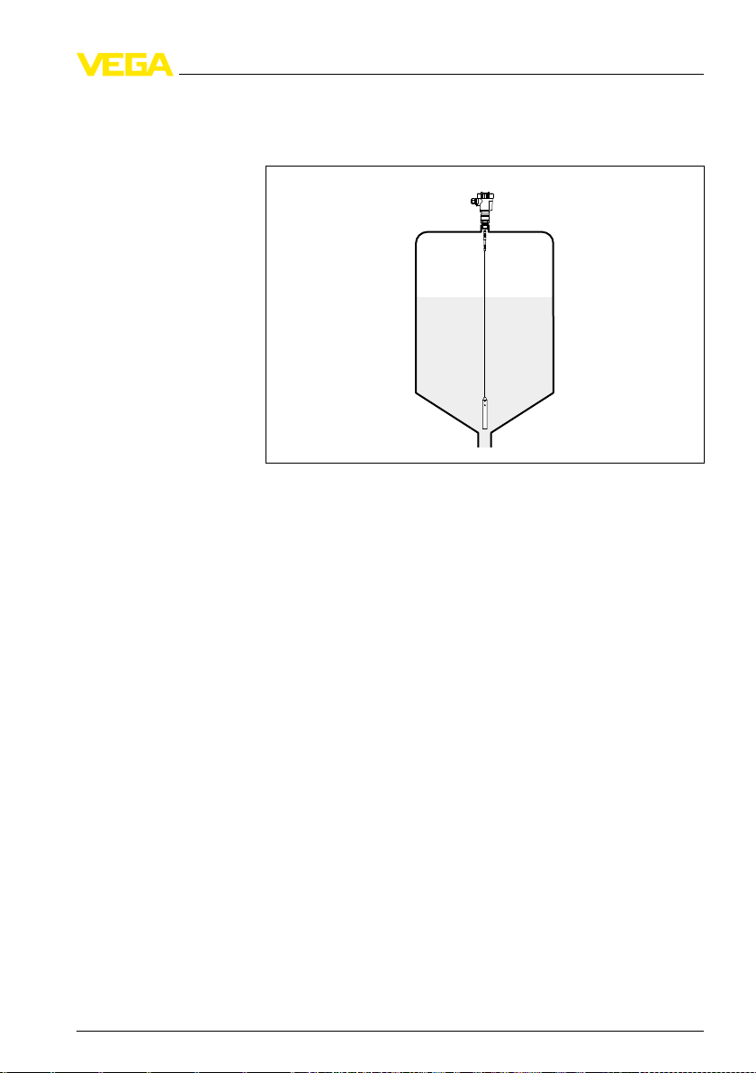
In vessels with conical bottom it can be advantageous to mount the
sensor in the center of the vessel, as measurement is then possible
down to the lowest point of the bottom. When using the cable version,
12 VE
31833-EN-100426
GAFLEX 61 • 4 … 20 mA/HART two-wire
ounting
4 M
keep in mind that measurement down to the tip of the probe is not
ble. The exact value of the min. distance (lower dead band) is
possi
stated in chapter "Technical data".
Vessel type
Fig. 3: Vessel
with conical bottom
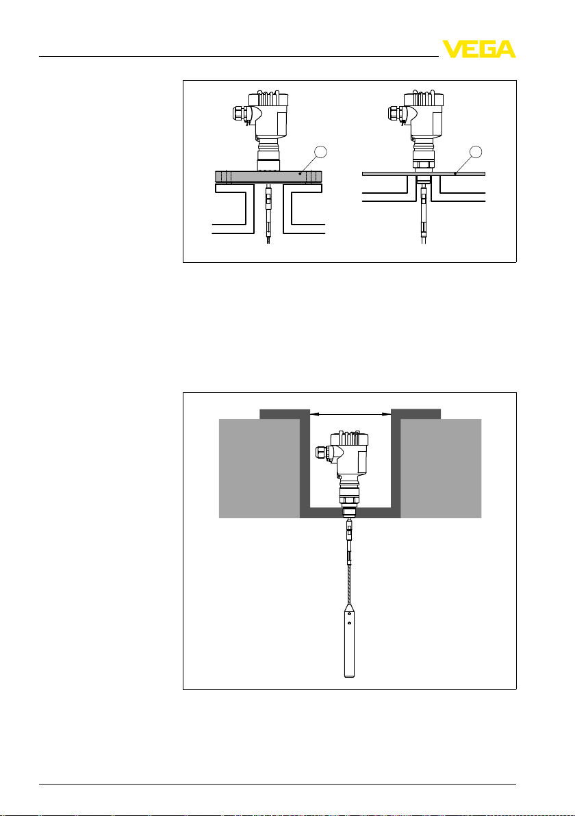
Plastic vessel/Glass vessel
The guided microwave principle requires a metal surface on the
process fitting. Therefore use in plastic vessels etc. an instrument
version with flange (from DN 50) or place a metal sheet (ø > 200 mm/
8 in) beneath the process fitting when screwing it in.
Make sure that the plate has direct contact with the process fitting.
In bypass tubes of plastic, a metal screen must be provided on the
outside. You can glue metal foil, for example, on the outside along the
entire length of the tube. This metal screen must be connected to the
ground terminal on the instrument.
When installing rod or cable probes without metal vessel wall, e.g. in
plastic vessels, the measured value can be influenced by strong
electromagnetic fields (emitted interference according to EN 61326:
class A).
In this case, use a probe in coax version.
31833-EN-100426
VEGAFLEX 61 • 4 … 20 mA/HAR
T two-wire 13
1 2
ø >160mm
(ø >6.3")
4 M
ounting
Fig. 4: Installation
1 Flange
2 Metal sheet
in plastic silo
Concrete vessel
When installed in thick concrete ceilings, VEGAFLEX 61 should be
mounted front flush to the lower edge. In concrete silos, the distance to
the wall should be at least 500 mm (20 in).
Fig. 5: Installation
in concrete silo
14 VE
31833-EN-100426
GAFLEX 61 • 4 … 20 mA/HART two-wire
h
d
d h
DN40 ... DN150 £ 150
> DN150 ... DN200 £ 100
1 2
4 M
ounting
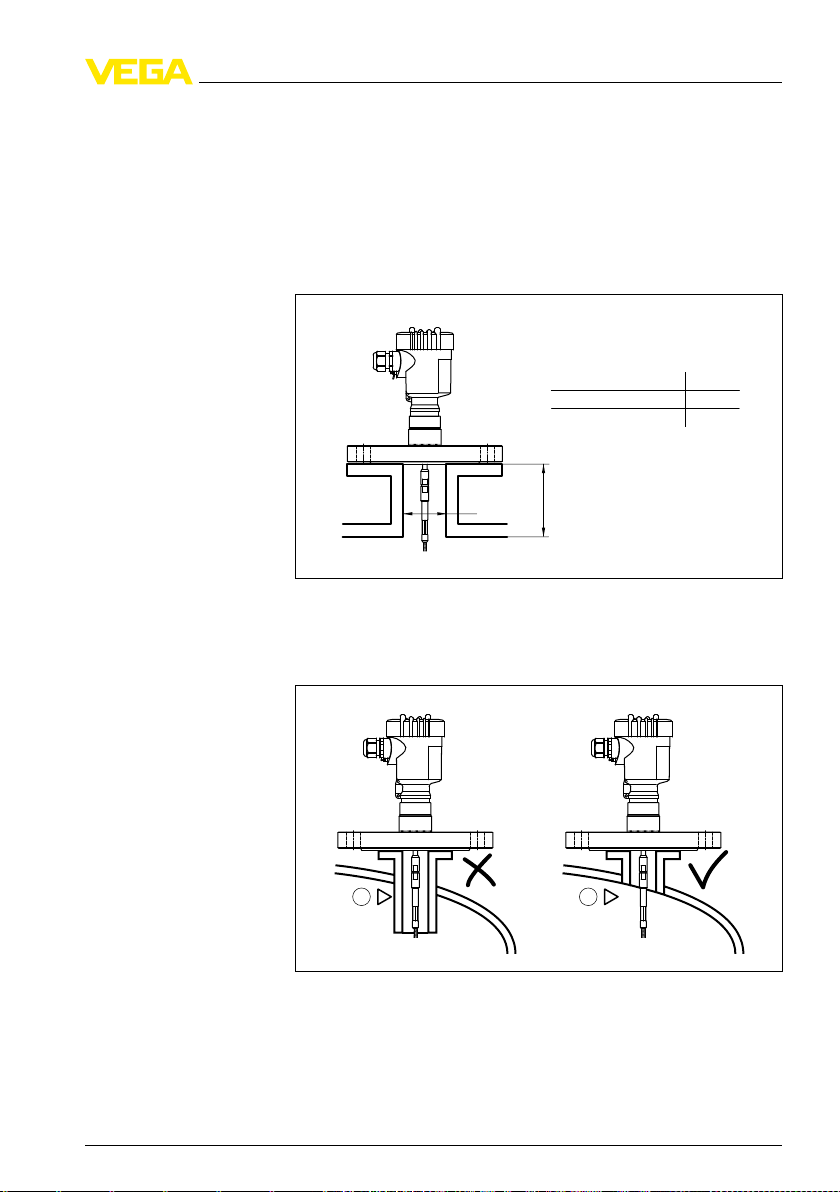
Socket
possible, avoid sockets. Mount the sensor flush with the vessel top. If
If
this is not possible, use short sockets with small diameter.
Higher sockets or sockets with a bigger diameter can generally be
used. They simply increase the upper dead band. Check if this is
relevant for your measurement.
In such cases, always carry out a gating out of false signals after
installation. You can find further information under "Setup procedure".
Fig. 6: Mounting
socket
When welding the socket, make sure that the socket is flush to the
vessel wall.
31833-EN-100426
VEGAFLEX 61 • 4 … 20 mA/HAR
Fig. 7: Socket
1 Unfavourable installation
2 Socket flush - optimum installation
must be installed flush
T two-wire 15
1
ounting
4 M
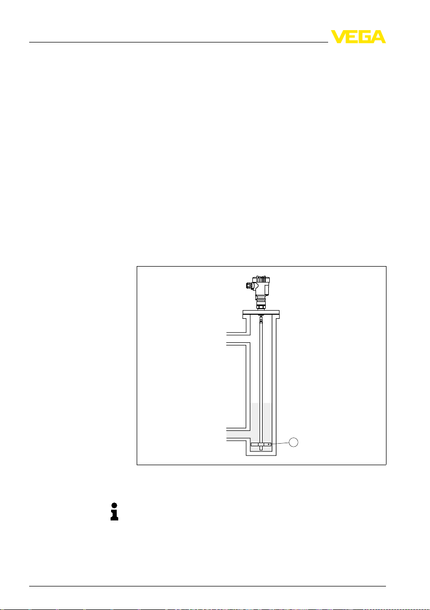
Standpipes or bypass
tubes
pes or bypass tubes are normally metal tubes with a diameter
Standpi
of 30 … 200 mm (1.18 … 7.87 in). In measurement technology such a
tube corresponds to a coax probe. It does not matter if the standpipe is
perforated or slotted for better mixing. Lateral inlets with bypass tubes
also do not influence the measurement.
Measuring probes can be mounted in bypass tubes up to DN 200.
If VEGAFLEX 61 is used in standpipes or bypass tubes, contact with
the tube wall should be avoided. We offer spacers as accessories for
fastening the probe in the middle of the tube.
Depending on the tube diameter or tube length, one or several spacers
can be mounted. With cable probes, the cable can also be strained to
avoid contact with the tube.
Keep in mind that buildup can form on the spacers. Strong buildup can
influence the measurement.
Microwaves can penetrate plastics. For process technical reasons,
plastic standpipes are problematic. If durability is no problem, then we
recommend the use of metal standpipes.
Fig. 8: Position
1 Spacer
of the spacer
Note:
Measu
rement in a standpipe is not recommended for very adhesive
products.
16 VE
31833-EN-100426
GAFLEX 61 • 4 … 20 mA/HART two-wire
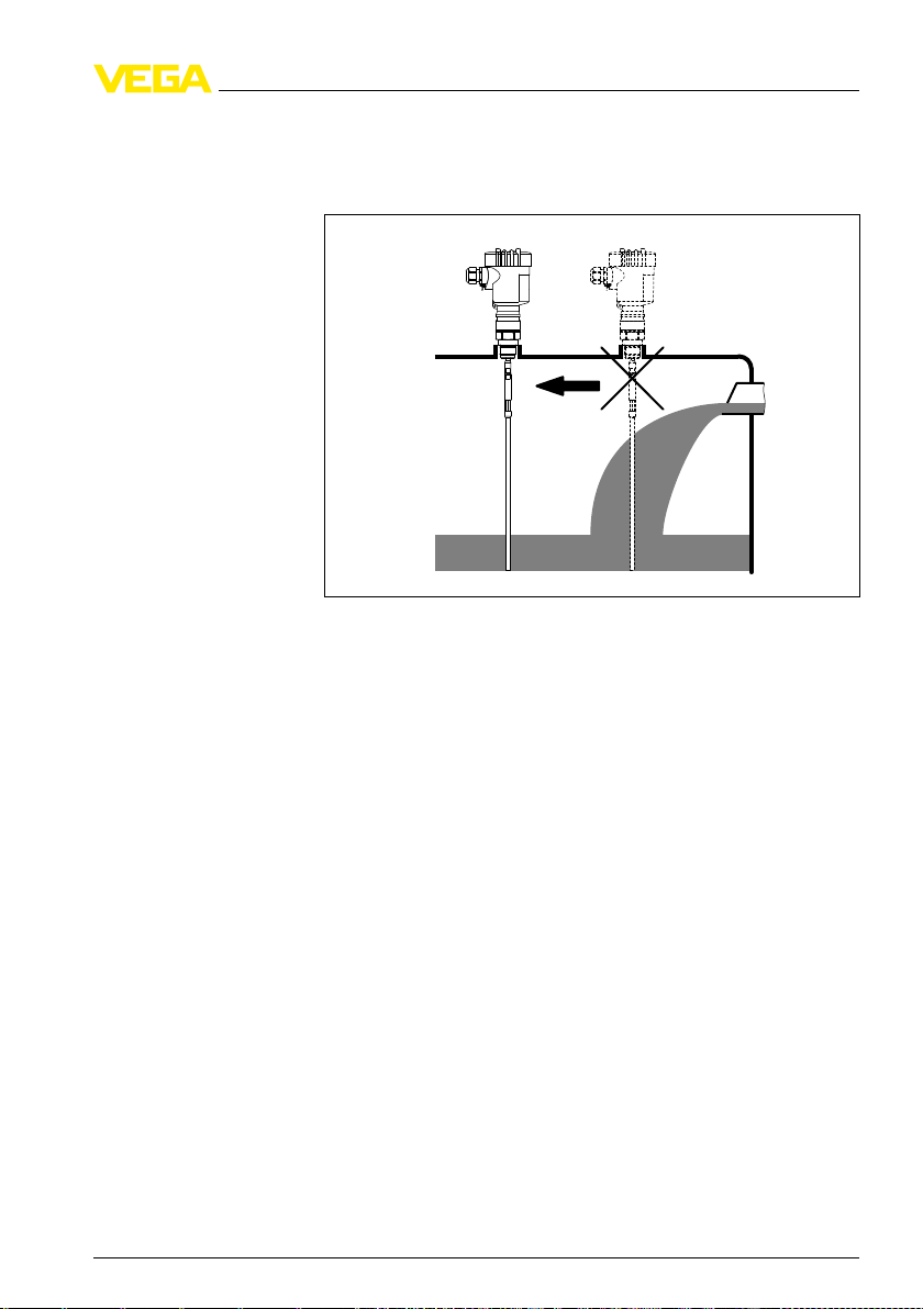
Inflowing medium
ounting
4 M
e sure that the probe is not subjected to strong lateral forces.
Mak
Mount VEGAFLEX 61 at a position in the vessel where no
disturbances, e.g. from filling openings, agitators, etc., can occur.
Fixing
31833-EN-100426
VEGAFLEX 61 • 4 … 20 mA/HAR
Fig. 9: Lateral
load
If there is a danger of the probe touching the vessel wall during
operation due to product movements or agitators etc., the measuring
probe should be securely fixed.
In the gravity weight there is a thread (M12), e.g. for a ring bolt
(optionally) - (article no. 2.27424).
Make sure that the probe cable is not completely taut. Avoid tensile
loads on the cable.
Avoid undefined cable-vessel connections, i.e. the connection must be
either grounded reliably or isolated reliably. Any deviation from this
requirement can lead to measurement errors.
T two-wire 17
ecting to power supply
5 Conn
Safety instructions
Voltage supply
Connection cable
5 Conn
ecting to power supply
5.1 Preparing the connection
Always keep in mind the following safety instructions:
l Connect only in the complete absence of line voltage
l If overvoltage surges are expected, overvoltage arresters should
be installed
Ti
p:
We recommend using VEGA overvoltage arresters B63-48 and
ÜSB 62-36G.X.
In
hazardous areas you should take note of the appropriate regulations,
conformity and type approval certificates of the sensors and power
supply units.
Power supply and current signal are carried on the same two-wire
cable. The voltage supply range can differ depending on the
instrument version.
The data for power supply are specified in chapter "Technical data".
Provide a reliable separation between the supply circuit and the mains
circuits according to DIN VDE 0106 part 101. The VEGA power supply
units VEGATRENN 149A Ex, VEGASTAB 690 as well as all
VEGAMETs and VEGASCANs meet this requirement.
Keep in mind the following additional influences on the operating
voltage:
l Output voltage of the power supply unit can be lower under
nominal load (with a sensor current of 20.5 mA or 22 mA in case of
fault message)
l Influence of additional instruments in the circuit (see load values in
chapter "Technical data")
The instrument is connected with standard two-wire cable without
screen. If electromagnetic interference is expected which is above the
test values of EN 61326 for industrial areas, screened cable should be
used.
Use cable with round cross-section. A cable outer diameter of 5 … 9 mm
(0.2 … 0.35 in) ensures the seal effect of the cable gland. If you are
using cable with a different diameter or cross-section, exchange the
seal or use a suitable cable gland.
We generally recommend the use of screened cable for HART
multidrop mode.
31833-EN-100426
Cable gland ½ NPT
18 VE
On the instrument with cable entry ½ NPT and plastic housing there is
a metallic ½" threaded insert moulded into the plastic housing.
GAFLEX 61 • 4 … 20 mA/HART two-wire
ecting to power supply
5 Conn
Caution:
grease should be used when screwing the NPT cable gland or
No
steel tube into the threaded insert. Standard grease can contain
additives that corrode the connection between threaded insert and
housing. This would influence the stability of the connection and the
tightness of the housing.
Cable screening and
grounding
If screened cable is necessary, connect the cable screen on both ends
to ground potential. In the sensor, the screen must be connected
directly to the internal ground terminal. The ground terminal on the
outside of the housing must be connected to the potential equalisation
(low impedance).
If potential equalisation currents are expected, the connection on the
processing side must be made via a ceramic capacitor (e. g. 1 nF,
1500 V). The low frequency potential equalisation currents are thus
suppressed, but the protective effect against high frequency interference signals remains.
Ta
ke note of the corresponding installation regulations for Ex
applications. In particular, make sure that no potential equalisation
currents flow over the cable screen. In case of grounding on both sides
this can be achieved by the use of a capacitor or a separate potential
equalisation.
5.2 Connection procedure
Proceed as follows:
1 Unscrew the housing cover
2 If an indicating and adjustment module is installed, remove it by
turning it slightly to the left.
3 Loosen compression nut of the cable entry
4 Remove approx. 10 cm (4 in) of the cable mantle, strip approx.
1 cm (0.4 in) of insulation from the ends of the individual wires
5 Insert the cable into the sensor through the cable entry
6 Lift the opening levers of the terminals with a screwdriver (see
following illustration)
31833-EN-100426
VEGAFLEX 61 • 4 … 20 mA/HAR
T two-wire 19

ecting to power supply
5 Conn
7 Insert
Fig. 10: Connection
8 Press down the opening levers of the terminals, you will hear the
9 Check the hold of the wires in the terminals by lightly pulling on
10 Connect the screen to the internal ground terminal, connect the
11 Tighten the compression nut of the cable entry. The seal ring must
12 Screw the housing cover on
The electrical connection is finished.
the wire ends into the open terminals according to the wiring
plan
steps 6 and 7
terminal spring closing
them
outer ground terminal to potential equalisation
completely encircle the cable
5.3 Wiring plan, single chamber housing
e following illustrations apply to the non-Ex as well as to the Ex-ia
Th
version.
20 VE
31833-EN-100426
GAFLEX 61 • 4 … 20 mA/HART two-wire
Loading...