


 Loading...
C-Soft
Software Console
Administrator’s Guide
version 4.000 and later
LIT000082000 Rev B |
April 2007 |
PROPRIETARY NOTICE
The product information and design disclosed herein were originated by and are the property of Telex Communications, Inc. Telex reserves all patent, proprietary design, manufacturing, reproduction, use and sales rights thereto, and to any article disclosed therein, except to the extent rights are expressly granted to others.
COPYRIGHT NOTICE
Copyright 2007 by Telex Communications, Inc. All rights reserved. Reproduction, in whole or in part, without prior written permission from Telex is prohibited.
WARRANTY NOTICE (LIMITED)
All Telex manufactured signaling products are guaranteed against malfunction due to defects in materials and workmanship for three (3) years, beginning at the original date of purchase.If such a malfunction occurs, the product will be repaired or replaced (at our option) without charge during the three (3) year period, if delivered to the Telex factory. Warranty does not extend to damage due to improper repairs, finish or appearance items, or malfunction due to abuse or operation under other than the specified conditions, nor does it extend to incidental or consequential damages. Some states do not allow the exclusion or limitation of incidental or consequential damages. Some states do not allow the exclusion or limitation of incidental or consequential damages, so the above limitation may not apply to you. This warranty gives the customer specific legal rights, and there may be other rights which vary from state to state.
FACTORY SERVICE CENTER
Factory Service Center
Telex Communications, Inc.
Radio Dispatch Products
8601 East Cornhusker Highway
Lincoln, Nebraska, 68507
PHONE NUMBERS |
|
Sales: |
|
Phone ................................................................... |
(800) 752-7560 |
Fax........................................................................ |
(402) 467-3279 |
E-mail................................................................. |
vega@telex.com |
Customer Service Repair: ................................................. |
(800) 553-5992 |
Technical Support: |
|
Phone ................................................................... |
(800) 898-6723 |
E-mail ............................................ |
acttechsupport@us.telex.com |
Web ................................................................................... |
www.telex.com |
CLAIMS |
|
No liability will be accepted for damages directly or indirectly arising from the use of our materials or from any other causes. Our liability shall be expressly limited to replacement or repair of defective materials.

Table
of
Contents
DESCRIPTION ................................................. |
7 |
Overview ................................................................. |
7 |
COMPUTER SYSTEM REQUIREMENTS ............................. |
7 |
C-SOFT APPLICATION SOFTWARE .................................. |
7 |
CSoftDesigner Program ........................................... |
7 |
CSoftRuntime Program ............................................ |
8 |
INSTALLATION AND SETUP ........................ |
9 |
Install the Software ................................................. |
9 |
License Dongle Driver Installation ...................... |
10 |
Initial Volume Control Settings ............................ |
11 |
PLAYBACK VOLUMES ................................................... |
11 |
RECORDING VOLUMES ................................................ |
11 |
COMMUNICATIONS SYSTEM DESIGN .... 13 |
|
Network Requirements .......................................... |
13 |
BANDWIDTH ................................................................ |
13 |
MULTICAST ................................................................. |
13 |
INTERNET GROUP MANAGEMENT PROTOCOL (IGMP) 14 |
|
NETWORK PERFORMANCE ........................................... |
14 |
CSOFTDESIGNER PROGRAM .................... |
15 |
Starting the CSoftDesigner Program ................... |
15 |
CSoftDesigner Window ......................................... |
15 |
TITLE BAR ................................................................... |
16 |
MENU BAR .................................................................. |
16 |
TOOLBAR .................................................................... |
16 |
CONSOLE WINDOW ..................................................... |
18 |
STATUS BAR ................................................................ |
18 |
Interface Element Manipulation ........................... |
19 |
File Menu .............................................................. |
22 |
OPEN .......................................................................... |
22 |
SAVE ........................................................................... |
22 |
EXIT ............................................................................ |
23 |
Edit Menu ............................................................. |
24 |
SETUP PER LINE PARAMETERS .................................... |
24 |
Line Number Field ................................................. |
25 |
Line Type Drop-down Menu .................................. |
25 |
Line Name Field ..................................................... |
25 |
RX and TX Multicast Address Fields ..................... |
25 |
RX and TX Port Fields ........................................... |
25 |
Base Radio IP Field ............................................... |
25 |
TTL (Time To Live) Field ....................................... |
26 |
Packet Delay Field ................................................. |
26 |
TxMon Enable Check Box ...................................... |
26 |
Scannable Check Box ............................................. |
26 |
Echo Packets Enable Check Box ............................ |
26 |
Backup IP Setup Button .......................................... |
27 |
BACKUP IP PARAMETERS WINDOW ............................. |
28 |
RX Multicast Address and Port Fields ................ |
28 |
TX Multicast Address and Port Fields ................ |
28 |
Base Radio IP Field ............................................ |
28 |
OK Button ............................................................ |
28 |
Cancel Button ...................................................... |
28 |
Freqs Button ........................................................... |
28 |
Per Line Frequency Setup Window 28 |
|
Enable Check Box ............................................... |
29 |
Frequency Name Field ........................................ |
29 |
Pair Mode Setup Check Boxes ............................ |
29 |
RX Block Lines Display Box ................................ |
30 |
Close Button ........................................................ |
30 |
Signal Setup Button ................................................ |
30 |
SIGNALING SETUP PARAMETERS .................................. |
30 |
Per Line Console ID field ....................................... |
31 |
Auto Ack Setup Group Box ..................................... |
31 |
Auto Ack Type drop down menu .......................... |
31 |
Auto Ack Delay field ............................................ |
31 |
Signaling Delays Group Box .................................. |
31 |
Initial Delay field ................................................ |
31 |
End Delay field .................................................... |
31 |
Global Group Box .................................................. |
31 |
Set All Lines check box ........................................ |
31 |
Single Tone Auto Ack Setup Group Box ................. |
31 |
Frequency field .................................................... |
31 |
Duration field ...................................................... |
32 |
Level field ............................................................ |
32 |
Signaling Setup Group Box .................................... |
32 |
Signaling Type drop-down menu ......................... |
32 |
Digit Duration field ............................................. |
32 |
Interdigit Duration field ...................................... |
32 |

Table
of
Contents
Pause Duration field ........................................... |
32 |
Preamble Duration field ..................................... |
32 |
Level field ............................................................ |
33 |
Twist Level field .................................................. |
33 |
Group Digit field ................................................. |
33 |
Repeat Digit ........................................................ |
33 |
Call Setup Group Box ............................................ |
33 |
Auto Ack field ...................................................... |
33 |
Emerg Resolved field ........................................... |
33 |
PTT BOT field ..................................................... |
34 |
PTT EOT field ..................................................... |
34 |
Call 1 through Call 10 Format field ................... |
34 |
Call 1 through Call 10 Label field ...................... |
35 |
AUTOFILL LINE PROPERTIES ....................................... |
36 |
OK Button ............................................................... |
36 |
Cancel Button ......................................................... |
36 |
SETUP GLOBAL PARAMETERS ...................................... |
37 |
DTMF Setup Group Box ........................................ |
37 |
Flywheel Field ..................................................... |
37 |
Level Field ........................................................... |
38 |
Supervisor Group Box ............................................ |
38 |
Timeout Field ...................................................... |
38 |
HB3 Serial Port Drop-down menu ......................... |
38 |
Local Console IP Address Fields ........................... |
38 |
IP Address or Name of License Server Field ......... |
38 |
Window Controls Check Boxes .............................. |
39 |
IP Interface Spin Box ............................................. |
39 |
Ring Sound Drop-down Menu ................................ |
39 |
Background Color .................................................. |
39 |
Logo Fields ............................................................. |
39 |
Bitmap Filename Field ........................................ |
39 |
Position Drop-down Menu .................................. |
39 |
Audio Routing and Muting Check Boxes ............... |
40 |
Kill Lines on Crosspatch Check Box ...................... |
40 |
Enable Sticky ANI Check Box ................................ |
40 |
Enable Residue ANI Check Box ............................. |
40 |
Allow Freq Update Anytime Check Box ................. |
40 |
Disable Local iDEN Tones Check Box .................. |
40 |
Radio Ping Interval Field ....................................... |
40 |
RX Block Delay Field ............................................. |
41 |
Tones/DTMF Sidetone Level Field ........................ |
41 |
MIC AGC Enabled Check Box .............................. |
41 |
Target Level Field .............................................. |
41 |
Min Active Field ................................................. |
41 |
Phone Ring Multicast and Port Fields .................. |
41 |
NEO-10 Update Multicast and Port Fields ........... |
41 |
Positional Recording Group Box ........................... |
41 |
OK Button .............................................................. |
42 |
Cancel Button ........................................................ |
42 |
SETUP GLOBAL CALL PARAMETERS ............................ |
42 |
Window Titles Group Box ...................................... |
42 |
Active Emergency Field ...................................... |
42 |
Emergency History Field .................................... |
43 |
Per Line Call History Field ................................ |
43 |
Call List Field ..................................................... |
43 |
Manual Call List Field ....................................... |
43 |
Status List Field .................................................. |
43 |
Call Options Group Box ........................................ |
43 |
Call-to-Console Color Field ............................... |
43 |
Change Color Button .......................................... |
43 |
Date Format Drop Down Menu ......................... |
43 |
Display All Calls Check Box .............................. |
44 |
Per Line Call History Window Lines Field ........ |
44 |
Per Line Call History Font Size Field ................ |
44 |
Emergency Call History Window Lines Field .... |
44 |
Emergency Call History Font Size Field ............ |
44 |
Active Emergency Font Size Field ...................... |
44 |
Call List Font Size Field ..................................... |
44 |
Status List Font Size Field .................................. |
44 |
Labels on Buttons Group Box ................................ |
44 |
ACK Field ........................................................... |
44 |
Resolved Field .................................................... |
44 |
Done Field .......................................................... |
44 |
Set Status Field ................................................... |
45 |
Clear Field .......................................................... |
45 |
Cancel Field ....................................................... |
45 |
Backspace Field .................................................. |
45 |
Digit A-F Fields .................................................. |
45 |
Labels on Column Headings and |
|
Static Text Group Box ........................................... |
45 |
Date Field ........................................................... |
45 |
Time Field ........................................................... |
45 |

Table
of
Contents
Channel Field ...................................................... |
45 |
Freq Field ........................................................... |
45 |
Status Field ......................................................... |
45 |
User ID Field ...................................................... |
45 |
Calling ID Field .................................................. |
46 |
Status ID Field .................................................... |
46 |
Alias Field ........................................................... |
46 |
ID Type Field ...................................................... |
46 |
OK Button .............................................................. |
46 |
Cancel Button ......................................................... |
46 |
Defaults Button ...................................................... |
46 |
PAGER SETUP ............................................................. |
47 |
Pager Number Field .............................................. |
47 |
Setup Button ........................................................... |
47 |
Send Sequentially Check box ................................. |
47 |
Correct Low Freq Tone Levels |
|
(Flatten Levels) Check box .................................... |
48 |
OK Button .............................................................. |
48 |
2 TONE 100 PAGE SETUP WINDOW ............................. |
48 |
Page Name Field .................................................... |
48 |
Page Level Field .................................................... |
48 |
Initial Delay Field .................................................. |
49 |
Tone 1 Group and Tone 2 Group Fields ................ |
49 |
Tone 1 Time Field .................................................. |
49 |
Gap Duration Field ................................................ |
49 |
Tone 2 Time Field .................................................. |
49 |
Group Tone Time Field .......................................... |
49 |
Enable Diagonal Check Box .................................. |
49 |
Diag Tone Freq Field ............................................ |
49 |
Diag Location Check Box ...................................... |
49 |
OK Button .............................................................. |
49 |
Cancel Button ......................................................... |
49 |
2 TONE 1000 SETUP WINDOW ..................................... |
51 |
Page Name Field .................................................... |
51 |
Page Level Field .................................................... |
51 |
Initial Delay Field .................................................. |
51 |
Tone Plan Number Field ........................................ |
51 |
Tone 1 Time Field .................................................. |
52 |
Gap Duration Field ................................................ |
52 |
Tone 2 Time Field .................................................. |
52 |
Group Tone Time Field .......................................... |
52 |
Enable Diagonal Check Box |
..................................52 |
Diag Tone Freq Field ............................................. |
52 |
Diag Location Check Box ...................................... |
52 |
OK Button ............................................................... |
53 |
Cancel Button ......................................................... |
53 |
DTMF PAGING SETUP WINDOW ................................. |
54 |
Page Name Field .................................................... |
54 |
Page Level Field ..................................................... |
54 |
Initial Delay Field .................................................. |
54 |
DTMF On Time Field ............................................. |
54 |
DTMF OFF Time Field .......................................... |
54 |
DTMF Digits Field ................................................. |
54 |
OK Button ............................................................... |
54 |
Cancel Button ......................................................... |
55 |
EDIT USER ID LIST ..................................................... |
55 |
Name Field ............................................................. |
55 |
Cancel Button ......................................................... |
55 |
EDIT USER ID LIST ..................................................... |
55 |
Name Field ............................................................. |
55 |
User ID Field ......................................................... |
56 |
Load File Button ..................................................... |
56 |
Save File Button ..................................................... |
56 |
Close Button ........................................................... |
56 |
EDIT GROUP ID LIST .................................................. |
57 |
Group Field ............................................................ |
57 |
Group ID Field ....................................................... |
57 |
Set Color Check Box .............................................. |
57 |
Set Color Button ..................................................... |
58 |
Load File Button ..................................................... |
58 |
Save File Button ..................................................... |
58 |
Uncheck All Button ................................................. |
58 |
Reset Colors ........................................................... |
58 |
Close Button ........................................................... |
58 |
EDIT STATUS MESSAGE ID LIST .................................. |
58 |
Status Message Field .............................................. |
59 |
Status ID Field ....................................................... |
59 |
Set Color Check Box .............................................. |
59 |
Set Color Button ..................................................... |
60 |
Load File Button ..................................................... |
60 |
Save File Button ..................................................... |
60 |
Uncheck All Button ................................................. |
60 |

Table
of
Contents
Reset Colors ........................................................... |
60 |
Close Button ........................................................... |
60 |
SCREEN DESIGN EDIT COMMANDS .............................. |
61 |
Insert Menu .......................................................... |
62 |
UI Element Setup window ...................................... |
62 |
TYPE TAB .................................................................... |
64 |
UI Element Function Drop-down Menu ................ |
64 |
Line to Associate Function With |
|
Drop-down Menu ................................................... |
64 |
OK Button ............................................................... |
64 |
COLORS TAB ............................................................... |
65 |
Button Up and Button Down Group Boxes ............ |
65 |
Button Drop-down Menu ..................................... |
65 |
Text Drop-down Menu ........................................ |
65 |
Button Bitmaps Fields ......................................... |
65 |
Up Position and Down Position Bitmap Fields .. |
66 |
Button Up Text Field .............................................. |
66 |
Button Down Text Field ......................................... |
66 |
Border Color Drop-down Menu ............................. |
66 |
Set Font Button ....................................................... |
66 |
OK Button ............................................................... |
66 |
ADD UI BUTTON ......................................................... |
67 |
ACTIVE EMERGENCY WINDOW .................................... |
67 |
ALERT ......................................................................... |
68 |
Tone Type Fields .................................................... |
68 |
Low Frequency Field ............................................. |
69 |
Low/On Duration Field .......................................... |
69 |
Hi Frequency Field ................................................ |
69 |
Hi/Off Duration Field ............................................ |
69 |
Tone Level Field ..................................................... |
69 |
AUTO-DIAL STRING ENTRY .......................................... |
70 |
Enter Dial String Field ........................................... |
70 |
BACKUP LINE .............................................................. |
71 |
Allow User to Switch |
|
Primary/Backup Check Box ................................... |
71 |
PER LINE CALL HISTORY 72 |
|
Call List Window .................................................... |
73 |
CROSSPATCH ............................................................... |
74 |
CROSSPATCH BLOCK ................................................... |
75 |
CROSSPATCH CLEAR ................................................... |
75 |
CROSSPATCH PROGRAMMED ....................................... |
75 |
Select Lines for Group Field .................................. |
76 |
Group Patch Number Drop-down Menu ............... |
76 |
Autostart Crosspatch Check Box ........................... |
76 |
CROSSPATCH PTT ...................................................... |
77 |
DTMF DIGIT ............................................................. |
78 |
DTMF Digit Drop-down Menu .............................. |
78 |
EMERGENCY ACK ....................................................... |
79 |
EMERGENCY HISTORY WINDOW .................................. |
80 |
EMERGENCY RESOLVE ................................................ |
80 |
ENCRYPTION ............................................................... |
80 |
FREQUENCY CHANGE ................................................. |
81 |
Select PTT Frequency Drop-down Menu .............. |
82 |
GROUP PROGRAMMED ................................................ |
83 |
Select Lines for Group Field .................................. |
83 |
GROUP SELECT .......................................................... |
84 |
GROUP SELECT LIMITED ............................................ |
84 |
Max Number of Simultaneous |
|
Selected Lines Field ............................................... |
84 |
INPUT INDICATION ...................................................... |
85 |
Input Source and Polarity Radio Buttons .............. |
85 |
Active High Check Box ....................................... |
86 |
Annunciation of Input Change Group Box ............ |
86 |
Input Destination Radio Buttons ........................... |
86 |
NEO Settings Group Box ....................................... |
86 |
IP Field ............................................................... |
86 |
Input Drop-down Menu ...................................... |
86 |
INSTANT RECALL ......................................................... |
87 |
Audio Playback Start Field .................................... |
87 |
Audio Source Drop-down Menu ............................ |
87 |
INTERCOM .................................................................. |
88 |
INTERCOM-PER LINE .................................................. |
88 |
Manual Call List Window ...................................... |
89 |
MARKER TONE ............................................................ |
90 |
Tone Type Radio Buttons ....................................... |
90 |
Low Frequency Field ............................................. |
90 |
Low/On Duration Field ......................................... |
90 |
Hi Frequency Field ................................................ |
91 |
Hi/Off Duration Field ............................................ |
91 |
Tone Level Field .................................................... |
91 |
Keyup Duration Field ............................................ |
91 |
Time Between Tones Field ..................................... |
91 |

Table
of
Contents
MONITOR .................................................................... |
91 |
MUTE GROUP ............................................................. |
92 |
MUTE MAIN ................................................................ |
93 |
MUTE - PER LINE ....................................................... |
93 |
Mute Time Field ..................................................... |
94 |
Min Mute Level Field ............................................. |
94 |
PAGE .......................................................................... |
95 |
Format Drop-Down Menu ..................................... |
95 |
Frequency Drop-Down Menu ................................ |
95 |
Talk Time Field ...................................................... |
95 |
Page String Field ................................................... |
95 |
Send on Selected (not steered) Check Box ............. |
95 |
PAGE MANUAL ENTRY ................................................. |
96 |
Initial Lead in Delay Field ..................................... |
97 |
Frequency Drop-Down Menu ................................ |
97 |
Tone Level Field .................................................... |
97 |
Tone #/Hz Fields .................................................... |
97 |
Talk Time Field ...................................................... |
97 |
Send on Selected (not steered) Check Box ............. |
97 |
PAGE SEND ................................................................. |
98 |
PAGE STACK ............................................................... |
98 |
Unlatch Stack Button After Page Check Box ......... |
98 |
PHONE-FLASHHOOK ................................................... |
99 |
PHONE-HOLD ............................................................. |
99 |
PHONE-ON/OFFHOOK .............................................. |
100 |
Remote Phone Number Drop-down Menu ........... |
100 |
PTT - MAIN .............................................................. |
101 |
PTT - PER LINE ........................................................ |
102 |
Select PTT Frequency Drop-down Menu ............ |
102 |
PTT - TALK BACK ..................................................... |
102 |
RADIO - ON/OFFHOOK ............................................. |
103 |
RELAY CONTROL BUTTON ......................................... |
103 |
Relay Destination Radio Buttons ......................... |
104 |
Relay Behavior Radio Buttons ............................. |
104 |
HB3 Settings Radio Buttons ................................. |
104 |
NEO Settings Field .............................................. |
104 |
IP Field ............................................................. |
104 |
Relay Drop-down Menu .................................... |
104 |
RX ALL ..................................................................... |
105 |
SCAN ......................................................................... |
105 |
SELECT ..................................................................... |
106 |
DTMF Digits for Select Call Field ...................... |
106 |
Annunciation of Select Call Group Box ............... |
107 |
Action on Select Call Field ................................... |
107 |
SUPERVISOR .............................................................. |
107 |
Enter Pin Number Field ....................................... |
108 |
TX ALL ..................................................................... |
109 |
ADD UI VOL. CONTROL ............................................ |
109 |
UI Element Function ............................................ |
110 |
Volume-Master Select ....................................... |
110 |
Volume-Master Unselect ................................... |
110 |
Volume - Per Line ............................................. |
110 |
Line to Associate Function |
|
With Drop-down Menu ......................................... |
110 |
OK Button ............................................................. |
110 |
VOLUME CONTROL TAB ............................................. |
111 |
Orientation Field .................................................. |
111 |
Minimum Volume Field ........................................ |
111 |
Maximum Gain Drop-down Menu ....................... |
111 |
Slider Background Color Drop-down Menu ....... |
111 |
ADD POPUP BUTTON ................................................ |
113 |
POPUP WINDOW CONTROL ....................................... |
114 |
POPUP CALL HISTORY ............................................... |
114 |
Include Muted Calls in List Check Box ................ |
115 |
Include NEO Changes in List Check Box ............. |
115 |
Call Window Lines Field ...................................... |
115 |
Call Window Font Size Field ............................... |
115 |
POPUP WEB PAGE .................................................... |
115 |
Webpage URL Field ............................................. |
116 |
Refresh Interval Field ........................................... |
116 |
Refresh when popup button is |
|
pressed Check Box ............................................... |
116 |
ADD TEXT ................................................................. |
116 |
Horizontal Check Box .......................................... |
117 |
Enter Text Field .................................................... |
117 |
OK Button ............................................................. |
117 |
Cancel Button ....................................................... |
117 |
CSOFTRUNTIME PROGRAM .................... |
119 |
Starting the CSoftRuntime Program ................... |
119 |
OPENING FILES ......................................................... |
119 |
CSoftRuntime Window ........................................ |
122 |
WINDOW SIZES .......................................................... |
122 |

Table
of
Contents
CONSOLE SCREEN |
|
DESIGN TUTORIAL .................................... |
125 |
START THE CSOFTDESIGNER PROGRAM ................... |
125 |
SETUP BASIC IP PARAMETERS .................................. |
125 |
CREATE A MASTER PTT, MONITOR, |
|
AND INTERCOM BUTTON ........................................... |
128 |
CREATE A COLUMN OF CONTROLS ........................... |
130 |
ADD A POPUP BUTTON ............................................ |
132 |
SAVING THE DESIGN ................................................. |
135 |
COPY AND CHANGE A GROUP OF ELEMENTS ............ |
136 |
COMPLETING THE CONSOLE DESIGN ........................ |
139 |
TEST THE DESIGN .................................................... |
143 |
Notes .................................................................. |
146 |
Notes .................................................................. |
147 |

CHAPTER 1
Description
Overview
The Telex C-Soft Console Software is a Microsoft Windows™ application that enables a PC with a full-duplex sound card and a network connection to monitor and control two-way radios connected to the network. Utilized in conjunction with an infrastructure of Telex VoIP (Voice Over Internet Protocol) products, the C-Soft application offers a powerful and convenient method for controlling a radio network using standard computer equipment.
The software console can support up to 200 lines and is fully compatible with popular touch screen monitors. In addition, the use of standard desk microphones, headsets, and foot-switches are supported through the use of the HB-3 Plus headset adapter panel.
Computer System Requirements
Operating System: Microsoft Windows 2000™ or Microsoft Windows XP™ required.
Sound System: Full duplex windows compatible sound system.
Network Connection: 10 Mbps or 100 Mbps, full-duplex TCP/IP connection. Static IP address preferred.
Processor Speed: Celeron 500 or greater, especially if controlling a large number of radios.
Memory: Minimum of 256Mb recommended.
C-Soft Application Software
CSoftDesigner Program
The CSoftDesigner program provides the ability to create custom dispatch screens with only those elements required by the end user. Console Operators with differing requirements can be given different screen designs. Once the screen layout is created, the CSoftDesigner program generates a file that is read by the CSoftRuntime program.
NOTE: The license dongle is not required to operate CSoftDesigner.
7

Description
CSoftRuntime Program
The CSoftRuntime program does the actual IP communications with the other radio elements available on the network. This single screen design file makes it easy for the designer to send updates to users wherever they may be located.
A license dongle is required to run the CSoftRuntime program. The dongle does not have to be in place to install the software, but is required to run the CSoftRuntime program.
8
CHAPTER 2
Installation and Setup
This section includes information on the installation of and the initial system setup requirements for the C-Soft programs:
•Install the Software
•License Dongle Driver Installation
•Initial Volume Control Settings
Install the Software
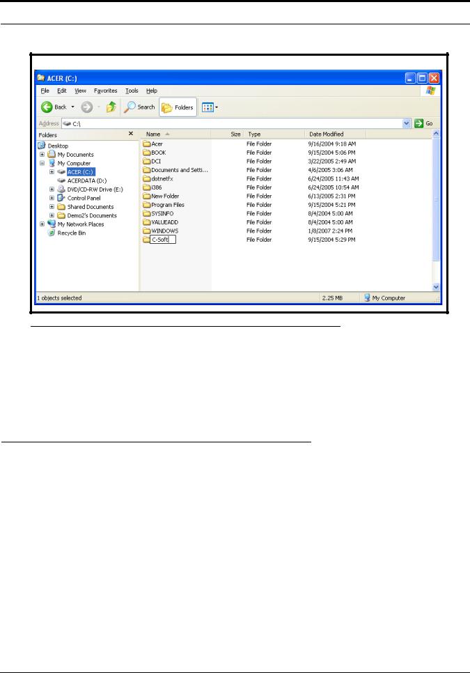
To install the CSoftDesigner and CSoftRuntime, do the following:
1.Insert the C-Soft CD into the CD/DVD drive on the computer.
2.Open Windows Explorer.
3.Select the local hard disk drive (typically drive C:\) in the left pane of Windows Explorer.
4.From the File menu, select New>Folder.
5.Rename the new folder to C-Soft.
9
Installation and Setup
FIGURE 1. Creating a C-Soft directory
6.Copy the CSoftRuntime.exe, CSoftDesigner.exe, C-Soft Administrators Guide (LIT000082000.pdf), and
C6200F_Default.veg files from the C-Soft directory on the CD.
7.Create desktop shortcuts for the CSoftRuntime.exe and CSoftDesigner.exe files.
NOTE: Adobe Reader® is required to view the C-Soft user manual. If Adobe Reader is not installed on the computer, a copy of Adobe Reader is included on the installation CD.
License Dongle Driver Installation
Before running the CSoftRuntime program, a driver must be installed that allows the program to access the license dongle.
To install the license dongle driver, do the following:
NOTE: Ensure no USB devices are installed in the USB ports on the computer during the driver installation.
1.Close all programs.
2.Insert the C-Soft CD into the CD/DVD drive on the computer.
3.From the Start menu, select Run.
The Run window opens.
4.In the Open field, type D:\SPNComboInst1.0.5.exe (substitute the appropriate letter of your CD-ROM drive for D).
5.Follow the installation wizard instructions.
6.After successful completion of the installation, restart the computer.
10

Initial Volume Control Settings
Initial Volume Control Settings
There are two sets of volume control settings on the computer that are crucial to the operation of the C-Soft programs. The first set controls playback volumes and the second set controls the recording volumes. Before operation of the C-Soft programs, these settings need to be checked and adjusted, if necessary.
Playback Volumes
The settings for playback volume should be similar to those shown in Figure 2.
To set the playback volume, do the following:
1.Double-click the speaker icon in the system tray.
The Volume Control screen appears.
FIGURE 2. Volume Control window
2.Set the Volume Control and Wave Volume to the maximum level.
3.Select the Mute checkbox for the microphone volume.
If the mute check box is not selected, the microphone audio will feedback from the speakers.
4.Close the Volume Control screen.
Recording Volumes
The settings for the recording volume should be similar to those shown in Figure 3 on page 12.
To set the recording volumes, do the following:
1.Double-click the speaker icon in the Windows tray.
The Volume Control window appears.
2.From the Options menu, select Properties.
The Properties window appears.
3.From the Adjust volume for area, select the Recording check box.
4.Select Microphone as the selected input.
11

Installation and Setup
5.Click OK.
The Recording Control window appears.
FIGURE 3. Recording Control window
6.Set the microphone volume control to approximately the second tick.
7.Close the Recording Control window.
NOTE: When using an HB-3+ with your system, you must turn OFF the Mic Boost function. On the Recording Control window, click Advanced. The Advanced Controls for Microphone window appears. Verify the Mic Boost check box is disabled.
12

CHAPTER 3
Communications System Design
Designing a C-Soft software console requires an understanding of the radio network and how the various radios and other communication equipment are connected.
The first step in designing a C-Soft dispatch screen is to create a roadmap of the radio, console, and any other communication equipment locations. This roadmap must include the following:
•Multicast addresses for each channel of TX (transmit) and RX (receive) communication.
•Port numbers for each channel of TX and RX communication.
•Base IP addresses assigned to each console or radio on the network and the number of frequencies that each radio operates on.
•The number of channels each radio may operate on.
Network Requirements
Bandwidth
Each VoIP channel requires 50kBit of bandwidth while active. Full-duplex (audio in each direction) conversation requires 100kBit of bandwidth.
Some radio systems transmit “go-ahead” beeps when it is clear to talk. In order for the console operator to hear the beeps, the system must support full-duplex communication. Full-duplex bandwidth may only be required for the first few seconds of a conversation, due to the brief nature of the “go-ahead” beeps at the beginning of the transmission.
When using a PIB-223, C-6200, or the NI-223 for a telephone connection, a full 100kBit is required since it is a full-time, fullduplex conversation.
Multicast
In general, Telex systems require multicast to function. The network must be able to create a static multicast address that is accessible at all times.
It is very common for networks to enable multicast after an IGMP (Internet Group Management Protocol) join message is sent out, and then “prune” off branches after a period of time. Due to the intermittent usage patterns of two-way radio, such a system can appear to work flawlessly for a period of time, then no longer work.
13

Communications System Design
NOTE: When using Cisco technology, IP PIM dense mode is generally recommended. Generally speaking, sparse- dense-mode can also be implemented effectively. We recommend explicitly joining the multicast group with an IP IGMP static-join X.X.X.X command. For more information on Cisco and IGMP visit www.cisco.com
Internet Group Management Protocol (IGMP)
IGMP can be used to control where multicast is allowed to propagate. This should be limited to subnets that utilize the C-Soft program as the dispatch console and only when used on an intermittent basis (when the C-Soft program is used for a period of time and then shut down). When a console on the subnet is expected to be continually operational, multicast must be active for that subnet at all times.
Network Performance
Networks should perform well under any loading conditions. The default audio delay is 120ms, plus any delay added by the network. While delay alone does not cause issues, variable delay (jitter) does. Jitter in a network cannot exceed the maximum packet buffer of any individual product buffer. Refer to the individual product manuals for these specifications. For example, the IP-223 can handle approximately 600ms of network jitter.
NOTE: Losing more than 5% of the total packets transmitted compromises audio quality and system performance. Optimally, packet loss should be less than 1%.
14

CHAPTER 4
CSoftDesigner Program
The CSoftDesigner program is a console designer application used by system specialists to design and configure custom dispatch screens. Various combinations of buttons, sliders, text, and popup windows can be included in a screen design. These elements are then configured to operate on specific lines.
The designer can place elements in any location desired, and can include or omit functions based on the requirements of the system and the console operator.
As discussed in the previous chapter, the first step in creating a user interface is defining how it will interact with an IP network. This includes knowing the TX and RX port of each radio, the multicast group(s) used, the number of radios to control, and the frequencies used by each radio.
Starting the CSoftDesigner Program
To start the CSoftDesigner program, double-click the CSoftDesigner desktop shortcut created during the installation of the program.
CSoftDesigner Window
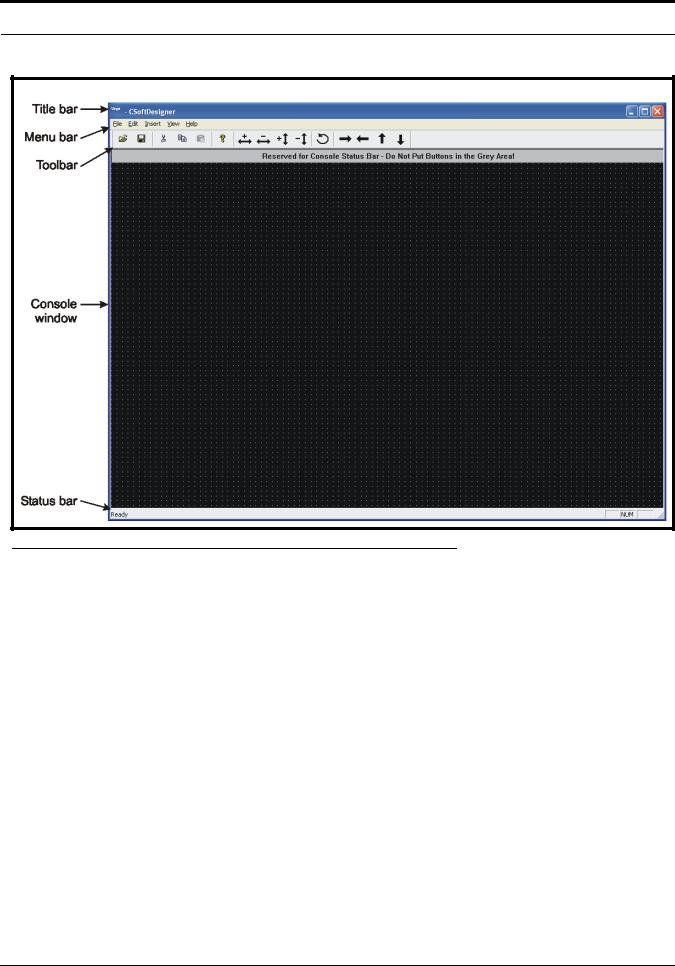
When the CSoftDesigner program is started, the console window shown in Figure 4 on page 16 is displayed. This window is the workspace. It contains the commands and tools needed to design and configure a customized software console.
The CSoftDesigner workspace includes the following components:
•Title Bar
•Menu Bar
•Toolbar
•Console Window
•Status Bar
15
CSoftDesigner Program
FIGURE 4. CSoftDesigner Workspace
Title Bar
The Title Bar is located across the top of each window. When a file is opened, the path sequence and file name are displayed on the title bar.
Menu Bar
The Menu Bar is located directly below the title bar and displays menus that contain commands for accessing the CSoftDesigner functions. For example, the Insert menu contains commands to add buttons, sliders, text, and popup windows.
Toolbar
The Toolbar is located directly below the menu bar and provides quick, easy access to commonly used tasks. See Table 1 on page 17 for a brief description of each button on the toolbar and the action taken when the button is selected.
To move the toolbar, do the following:
>Click, hold and drag the move handle on the toolbar or the title bar (blue bar) on a floating toolbar to the new location.
The toolbar can be docked on any side of the window. It can also operate as a floating toolbar, inside or outside the workspace.
16

CSoftDesigner Window
To display the toolbar, do the following:
>From the View menu, select Toolbar.
The toolbar appears in the spot where it was previously closed.
To hide the toolbar, do the following:
1.From the View menu, select Toolbar.
The toolbar closes.
2.When the toolbar is floating, click the x button in the upper right corner of the toolbar window
The toolbar closes.
TABLE 1. CSoftDesigner toolbar
Icon |
Tool Name |
|
Description |
|
Open |
Open an existing console design. You can also use File|Open. |
|
|
|
|
|
|
Save |
Save the current console design. You can also use File|Save. |
|
|
|
|
|
|
|
Delete the selected item(s). You can also use Edit|Cut or the Delete key on the |
|
|
Cut |
keyboard. |
|
|
|
|
|
|
|
NOTE: |
This does not place the cut item in the clipboard. |
|
|
|
|
|
Copy |
Copy the selected item(s). You can also use Edit|Copy. |
|
|
NOTE: |
This places the copied item in the clipboard. |
|
|
|
||
|
|
|
|
|
Paste |
Insert the item(s) on the clipboard into the console design. You can also use |
|
|
Edit|Paste. |
|
|
|
|
|
|
|
|
|
|
|
About |
Display the software version, company contact information, and various statistics |
|
|
about the console design. You can also use Help|About CSoftDesigner. |
||
|
|
||
|
|
|
|
|
|
Increase the width of the selected element. Proportionally increase the size of the |
|
|
|
selected text. |
|
|
|
|
|
|
|
Decrease the width of the selected element. Proportionally decrease the size of |
|
|
|
the selected text. |
|
|
|
|
|
17

CSoftDesigner Program
TABLE 1. CSoftDesigner toolbar
Icon |
Tool Name |
Description |
|
|
Increase the height of the selected element. Proportionally increase the size of the |
|
|
selected text. |
|
|
|
|
|
Decrease the height of the selected element. Proportionally decrease the size of |
|
|
the selected text. |
|
|
|
|
|
Rotate the selected popup window 90° counter-clockwise around the selected |
|
|
popup button. Rotate the selected text 90° counter-clockwise. |
|
|
|
|
|
Move the selected item(s) to the right. |
|
|
|
|
|
Move the selected item(s) to the left. |
|
|
|
|
|
Move the selected item(s) up. |
|
|
|
|
|
Move the selected item(s) down. |
|
|
|
Console Window
The Console Window displays the open console design. The console window contains a grid for easy alignment of elements on the screen. The grid is a screen alignment tool and is not displayed on the dispatch screen.
Status Bar
The Status Bar is located at the bottom of the workspace window. Positioning the mouse over a tool or menu command displays information about the tool or menu command on the status bar.
To display or hide the status bar, do the following:
>From the View menu, select Status Bar.
18
Interface Element Manipulation
Interface Element Manipulation
The CSoftDesigner program is heavily dependent on the mouse for interacting with the elements that comprise the console screen design. The mouse is used for selecting and moving objects, to access a form or window, and to perform actions on the displayed element or text.
Several standard Windows shortcut keys are supported, and are listed next to the command on the menu. This section describes the unique features of the CSoftDesigner program that are available to assist in the manipulation of the components on the console window.
To select a single item, do the following:
>Click the desired item.
A red target is displayed on the selected element, or in the case of text, there is a bounding outline around the selected text.
To select a group items, do the following:
1.Position the mouse pointer at the top and to the side of the objects to be selected.
2.Press and hold the left mouse button while dragging the mouse over the objects to be selected.
This draws a box around the items selected.
3.When all items are included within the box, release the mouse button.
A red target appears on the selected element(s), and, in the case of text, there is a box around the selected text, as shown in Figure 5.
FIGURE 5. Selected items
Once an item(s) is selected, the screen design edit commands (see “Screen Design Edit Commands” on page 61) can be performed on the item(s).
NOTE: A group of items cannot be moved using the mouse. Once selected, the positioning tools on the toolbar must be used to move the items as a group. The arrow keys on the keyboard cannot be used to move the items.
To move an individual item, do the following:
>Select the item to be moved and then drag it to its new location on the screen.
19

CSoftDesigner Program
To copy and move an individual item at the same time, do the following:
>Select the item while holding down the CTRL key and drag the item with the mouse to the new location on the screen.
This moves the copied item into the new location with all the parameters of the copied item intact. When a popup button is copied using the CTRL key, the popup window is also copied.
Using the CTRL key to copy items allows for large sections of the console screen to be designed, copied, and then modified slightly to quickly design the console screen.
To change the line number associated with a group of items, do the following:
1.Select a group of items.
2.Right-click an element within the selected group.
A shortcut menu appears.
3.From the shortcut menu, select Group Line Number.
The UI Group Properties window appears.
4.From the Line to Associate Function With drop-down menu, select the line to associate with the selected group.
5.Click OK.
To change the font used on the elements in the group, do the following:
1.Select a group of items.
2.Right-click an element within the selected group.
A shortcut menu appears.
3.From the shortcut menu, select Group Font Change.
The Font window appears.
4.Select the Font, Font style, and Size you want to display on the elements.
A sample of the chosen style displays in the Sample field at the bottom of the Font window.
5.Click OK.
FIGURE 6. UI Group Properties and Font windows
The position of the popup window in relation to the popup button can be changed. Follow the procedure below to change the position of the popup window.
To change the position of a popup window, do the following:
1.Right-click a UI element popup button.
A shortcut menu appears.
2.From the shortcut menu, select Open Popup.
A popup window appears.
20
Interface Element Manipulation
3.Select the rotate icon  from the toolbar.
Each click on the tool rotates the window 90° counter-clockwise around the selected popup button.
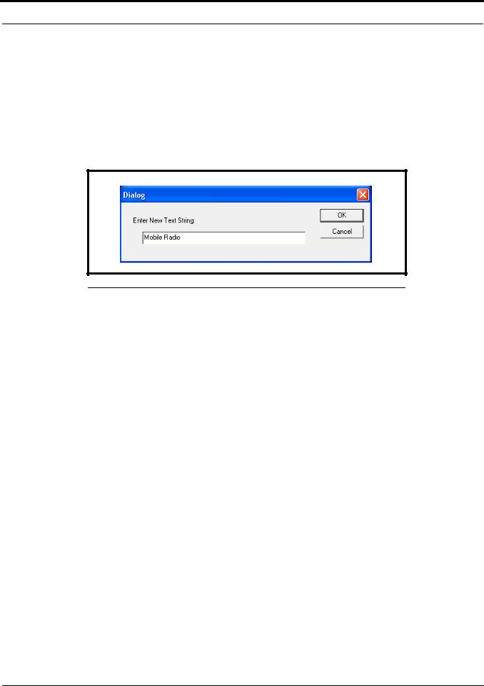
To change to a text string, do the following:
1.Select the text you want to change.
A bounding outline appears around the text.
2.Right-click on the text.
A Dialog window appears.
3.In the Enter New Text String field, make the changes to the text.
FIGURE 7. Enter New Text String window
4.Click OK to accept the changes. Otherwise, click Cancel.
The text is changed.
To change the size of a button, volume control or text string, do the following:
1.Select an item or group of items.
2.Use the increase or decrease width and height icons  to resize the selected element(s).
To change the size of a popup window, do the following:
1.Right-click a UI element popup button.
A shortcut menu appears.
2.From the shortcut menu, select Open Popup.
A popup window appears.
3.With the popup button selected (see Figure 8), use the increase or decrease width and height icons
 to resize the popup window.
21

CSoftDesigner Program
FIGURE 8. Popup Button selected while popup window open.
Additional details on editing items on the console window are provided in Screen Design Edit commands in Table 1 on page 17.
File Menu
The File menu contains commands for working with files. Each of the menu items is described below.
Open
Selecting Open from the File menu displays the Open window. Only files in the Designer file format (*.veg) can be opened by the CSoftDesigner program.
Save
Selecting Save from the File menu displays the Save As window. The CSoftDesigner program saves all files in the Designer File format (*.veg).
When a file is saved, the default name of C6200F_Default is in the File Name field in the Save As window. To use a different file name, type the desired name for the file in the File Name field. When using a file name other than C6200_Default, the file must be associated with the C-Soft program before it can be opened by the CSoftRuntime program. This is explained in detail in “CSoftRuntime Program” on page 119.
22

File Menu
When the file is saved, the CSoftDesigner program performs a validation on the console design. The results of the validation are displayed in the Design Errors window shown in Figure 9.
FIGURE 9. Design Errors window
If design errors are found, the last line of the list reads:
--------------------End of Error List--------------------
If no design errors are found, the last line of the list reads:
--------------------No Errors Found--------------------
NOTE: When all the results cannot be displayed within the window, scroll bars are provided on the window to scroll all of the test results.
Exit
Selecting Exit from the File menu closes the CSoftDesigner program.
23

CSoftDesigner Program
Edit Menu
The Edit menu contains commands for the setup and revision of the parameters for the VoIP network. This menu also contains commands for making changes to the parameters that apply to the individual elements of the console screen design. This section includes details about each of the commands that are on the Edit menu.
Setup Per Line Parameters
Selecting Setup Per Line Parameters from the Edit menu displays the Per Line Parameters window shown in Figure 10. The Per Line Parameters window is used to configure the line types, addresses, port information, and line frequencies for the VoIP network. This window allows up to 200 separate entries to be configured.
Many of the windows associated with the setup of the user interface elements depend on the entries on this setup window. The parameters for all lines that are to be included in the console design must be set up on this window, along with the frequencies associated with that line. If the line is not set up on this window, the line is not available as an option when setting up the user interface elements.
The fields on this window are described on the following pages.
NOTE: Additions and changes can be made to the Per Line Parameters window at any time. However, if any user interface elements have been placed on the console screen, the changes made to a line must also be changed on the individual elements, if needed.
FIGURE 10. Per Line Parameters window
24

Edit Menu
Line Number Field
The Line Number field displays the number of the line. This number is used for identification purposes in the design of the console screen.
Line Type Drop-down Menu
The Line Type drop-down menu identifies the type of line being configured. Once a selection is made in the line type field, the fields necessary to enter the setup information for that line type are enabled. The selections available are:
Disabled-Line is not enabled. Line 1 cannot be disabled.
Vega-Compatible with Telex radio control over IP products, such as the C-6200 or the IP-223
Not Used-
Phone- Allows the console to access a telephone line from across the network.
Line Name Field
The Line Name field is used to enter a descriptive name for the line. This name is used for identification purposes in the design of the console screen. Up to 30 characters can be entered into this field.
RX and TX Multicast Address Fields
The RX and TX Multicast Address fields identify the broadcast address for all audio traffic. This dotted quad number must be between 224.0.0.2 and 239.255.255.255. Devices can have the same or different Multicast Address for TX and RX channels. Telex VoIP enabled equipment can use one multicast address for all lines with the port number defining the TX and RX channels.
RX and TX Port Fields
The RX and TX Port fields identify the RX and TX port numbers. These numbers must be unique per channel and must be greater than 1054.
In Figure 10, the RX Port is 1054 and the TX Port is 1254 for Line 1. All consoles that want to monitor receive audio for channel 1 must share the same multicast address, as well as the same RX port number. Any console on the network that wishes to transmit must set its port number to 1254 to cause the radio to keyup.
Base Radio IP Field
The Base Radio IP field identifies the IP address of the IP-223 used by the C-Soft program to create a socket between two IP addresses. This address is required for the C-Soft program to create an internal ping command. It is also required for fullduplex mode (i.e., telephone mode) and to generate encoded message strings (i.e., 5/6 Tone, MDC 1200 and Fleetsync). We recommend you include a base radio IP address for all lines within your system design.
The base radio IP address is periodically pinged to determine if a network connection still exists for a particular radio. If there is no response received from the ping, the backup IP radio addresses are used.
A backup button is available for the console design. This button is used to force a switch, or to monitor whether the primary or backup channel is used. Additional details on this feature are provided in “Backup Line” on page 71.
25

CSoftDesigner Program
TTL (Time To Live) Field
The TTL field identifies the number of routers the multicast audio packets will go through before being stopped. The network design dictates this value. If audio is not reaching a particular node on the network, increasing this value may correct the problem.
Packet Delay Field
The Packet Delay field identifies the length of delay before playback, in 20ms packets. Some buffering of these packets must occur before playback to help absorb network delays, jitters, and lost packets. The typical entry for this field is 6, which translates to a delay of 120ms before playback (each packet is 20ms of audio). Larger values may be required for complicated networks, smaller values for simpler networks.
The variable range for this field is 4 to 27.
TxMon Enable Check Box
The TxMon Enable check box indicates whether or not TX traffic being sent from other console operators can be monitored. If selected, the console operator can monitor TX traffic from other console operators.
Scannable Check Box
The Scannable check box indicates whether or not the console operator is allowed to control the scan list of a particular radio. If selected, the console operator is allowed to control the scan list of a particular radio. The frequency buttons for the line can be used to add or delete radio channels from the scan list. Additional details on this feature are provided in “Frequency Change” on page 81.
Echo Packets Enable Check Box
The Echo Packets Enable check box indicates if the system will operate on networks that do not support multicast. If selected, the system is allowed to operate on networks that do not support multicast. The C-Soft program must be running at all times to translate and transfer packets from one IP subnet to another.
A typical application has a number of radios spread throughout a network without multicast. In this case, the radio adapters (IP-223s or C-6200s) are programmed to send packets to the IP address of the PC running the C-Soft program with Echo Packets enabled.
26
Edit Menu
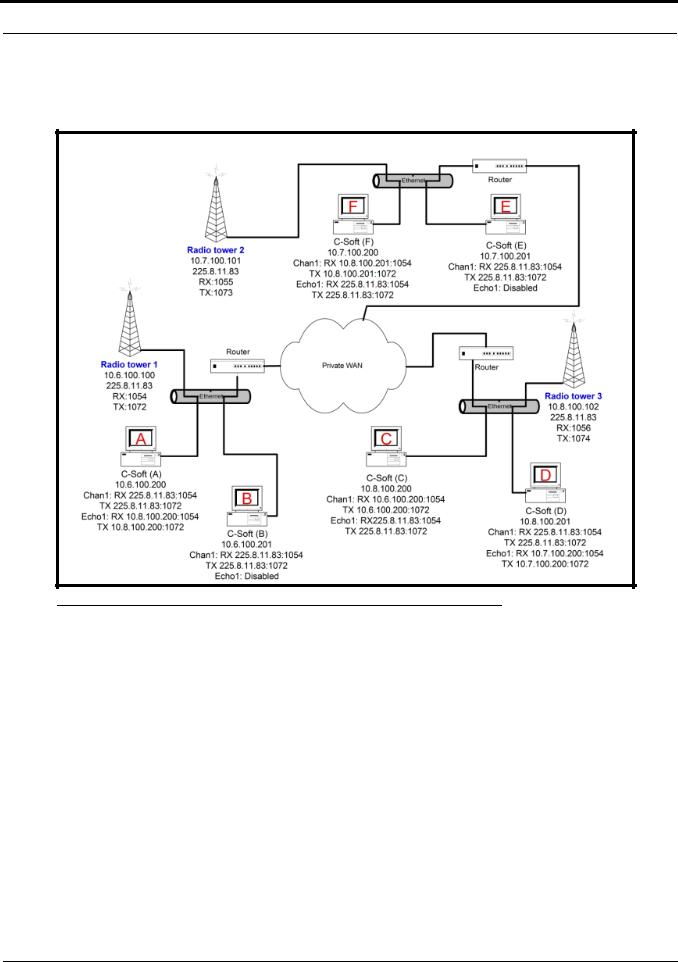
Figure 11 shows an example of an Echo Packet system where three different radios are connected through a WAN. In each of the subnets, a single copy of the C-Soft program is used to communicate to the radio in its subnet. A second console is used to echo the audio traffic to other copies of the C-Soft program. The C-Soft program also echoes all traffic to a multicast address within its subnet so that additional consoles can be added to the system by specifying the multicast address.
FIGURE 11. Echo Packet System Diagram
Traffic received on the address of the RX packet (typically multicast but under this scenario it is the unicast address of the radio remote) is copied and output to the RX echo packet address.
The echo packet RX address would typically be the multicast address. This enables the C-Soft program to function as a gateway for other consoles on the same local network segment. Local consoles transmit and receive the multicast address, and the C-Soft program translates and sends the packets to the radio directly.
The TX side works in a similar fashion, except the packets received on either address are echoed to the other address and when the C-Soft program transmits, it sends to both ports simultaneously.
NOTE: Echo packets support radio traffic only. Echo packets do not support Phone or NEO-10 functions.
Backup IP Setup Button
Selecting the Backup IP Setup button opens the Backup IP Address Setup window shown in Figure 12. If the primary radio interface identified for the line fails, the network resources identified in this window provide a backup for the line.
27
CSoftDesigner Program
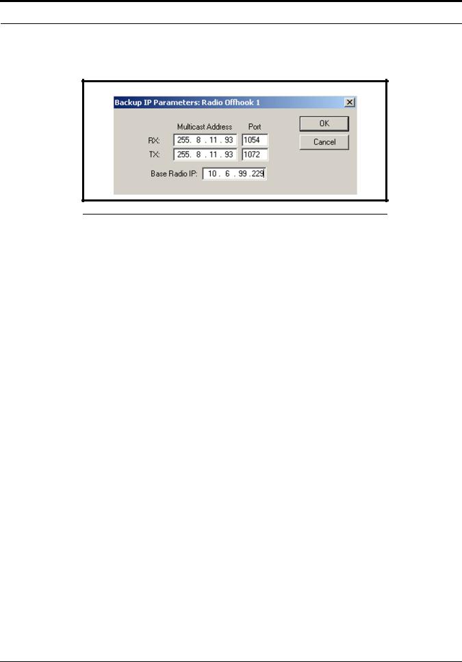
Backup IP Parameters Window
The Backup IP Parameters window identifies the network resources used if the primary radio interface identified for the line fails (see Figure 12).
FIGURE 12. Backup IP Parameters window
RX Multicast Address and Port Fields
Use the RX Multicast Address and Port fields to configure the receive multicast address and port to use if the primary receive path fails.
TX Multicast Address and Port Fields
Use the TX Multicast Address and Port fields to configure the transmit multicast address and port to use if the primary transmit path fails.
Base Radio IP Field
Use the Base Radio IP field to configure the backup IP Address of the base radio, should the primary address fail.
OK Button
Selecting the OK button saves the entries and closes the window.
Cancel Button
Selecting the Cancel button clears any entries made and closes the window.
Freqs Button
Selecting the Freqs button opens the Per Line Frequency Setup window shown in Figure 13 for the selected line.
Per Line Frequency Setup Window
The Per Line Frequency Setup window is used to enter the parameters for the individual function tones available for the line.
28
Loading...