


ISGSTM
Intelligent SwitchGear System Operator’s Manual–firmware version V3
Manual No. SG8158-00
IMPORTANT
The information contained herein is general in nature and not intended for specific application purposes. It does not relieve the user of responsibility to use sound practices in application, installation, operation, and maintenance of the equipment purchased. Siemens reserves the right to make changes at any time without notice or obligations. Should a conflict arise between the general information contained in this publication and the contents of drawings or supplementary material, or both, the latter shall take precedence.
QUALIFIED PERSON
For the purposes of this manual, a qualified person is one who is familiar with the installation, construction, or operation of the equipment and the hazards involved. In addition, this person has the following qualifications:
(a)is trained and authorized to de-energize, clear, ground, and tag circuits and equipment in accordance with established safety practices.
(b)is trained in the proper care and use of protective equipment such as rubber gloves, hard hat, safety glasses or face shields, flash clothing, etc. in accordance with established safety procedures.
(c)is trained in rendering first aid.
NOTE
These instructions do not purport to cover all details or variations in equipment, nor to provide for every possible contingency to be met in connection with installation, operation, or maintenance. Should further information be desired or should particular problems arise which are not covered sufficiently for the purchaser’s purposes, the matter should be referred to the local sales office.
The contents of the instruction manual shall not become part of or modify any prior or existing agreement, commitment or relationship. The sales contract contains the entire obligation of Siemens Energy & Automation, Inc. The warranty contained in the contract between parties is the sole warranty of Siemens Energy & Automation, Inc. Any statements contained herein do not create new warranties or modify the existing warranty.

Table
of
Contents
Siemens Energy & Automation, Inc.
Introduction
Installation
User Interface
Hardware Configuration
Protective Function Configuration
Control & Communications
Data Acquisition
ISGS Wisdom Software
Trip Curves & Equations
Metering
Menu Structure
Acceptance Test Procedures
Schematics
Settings Worksheet
Glossary
Index
1
2
3
4
5
6
7
8
A
B
C
D
E
S
G
I

Table of Contents
1 |
Introduction ............................................... |
1 |
||
|
1.1 |
About this Manual............................................. |
1 |
|
|
1.2 |
Safety................................................................ |
|
1 |
|
1.3 |
Product Description .......................................... |
2 |
|
|
|
1.3.1 |
Standard Configuration......................... |
2 |
|
|
1.3.2 |
Optional Configurations ........................ |
3 |
|
1.4 |
Wisdom Software.............................................. |
3 |
|
|
1.5 |
Technical Specifications ................................... |
4 |
|
2 |
Installation ................................................. |
5 |
||
|
2.1 |
Unpacking......................................................... |
5 |
|
|
2.2 |
Storing............................................................... |
|
5 |
|
2.3 |
Mounting........................................................... |
5 |
|
|
2.4 |
Wiring................................................................ |
|
6 |
|
2.5 |
Communications............................................... |
8 |
|
|
|
2.5.1 |
PC Communications (RS-232) .............. |
8 |
|
|
2.5.2 |
Network Communications (RS-485) ..... |
8 |
|
2.6 |
Cradle Assembly............................................... |
8 |
|
|
|
2.6.1 |
Removing .............................................. |
8 |
|
|
2.6.2 |
Inserting ................................................ |
8 |
3 |
User Interface............................................ |
9 |
||
|
3.1 |
Keypad.............................................................. |
9 |
|
|
3.2 |
Indicators .......................................................... |
9 |
|
|
|
3.2.1 |
LEDs...................................................... |
9 |
|
|
3.2.2 |
LCD ..................................................... |
10 |
|
3.3 |
Password Protection....................................... |
10 |
|
|
3.4 |
Menu ............................................................... |
|
11 |
|
3.5 |
Standard Operating Procedures ..................... |
11 |
|
4 |
Hardware Configuration......................... |
15 |
||
|
4.1 |
Startup ............................................................ |
15 |
|
|
|
4.1.1 |
Power On Display................................ |
15 |
|
|
4.1.2 Power On Meter Display ..................... |
15 |
|
|
4.2 |
Device Configuration ...................................... |
16 |
|
|
4.3 |
Setting Binary Input Voltages.......................... |
16 |
|
|
4.4 |
CT Configuration............................................. |
18 |
|
|
4.5 |
VT Configuration ............................................. |
18 |
|
5 |
Protective Function Configuration ........ |
21 |
||
|
5.1 |
Overview ......................................................... |
21 |
|
|
5.2 |
Instantaneous Phase Overcurrent (50)............ |
21 |
|
5.3High-Set Instantaneous Phase
Overcurrent (50HS) ......................................... |
22 |
5.4Instantaneous Neutral or Ground
Overcurrent (50N)............................................ |
22 |
5.5High-Set Instantaneous Neutral or
Ground Overcurrent (50HSN).......................... |
22 |
5Protective Function Configuration (cont.)
5.6 |
Phase Time Overcurrent (51)........................... |
23 |
5.7 |
Neutral Time Overcurrent (51N) ...................... |
23 |
5.8Blocking Capability for Breaker or
|
|
Interrupter Saving............................................ |
24 |
|
|
5.9 |
Directional Phase Time Overcurrent (67)......... |
24 |
|
|
5.10 |
Directional Neutral or Ground Time |
|
|
|
|
Overcurrent (67N)............................................ |
25 |
|
|
5.11 |
Overvoltage (59) .............................................. |
26 |
|
|
5.12 |
Undervoltage (27)............................................ |
26 |
|
|
5.13 |
Phase Sequence Voltage (47) ......................... |
27 |
|
|
5.14 |
Negative Sequence Voltage (47N) .................. |
27 |
|
|
5.15 |
Overfrequency (81O) ....................................... |
28 |
|
|
5.16 |
Underfrequency (81U) ..................................... |
28 |
|
|
5.17 |
Breaker Failure (50BF)..................................... |
28 |
|
|
5.18 |
Demand Setpoints .......................................... |
29 |
|
|
5.19 |
Power Setpoints.............................................. |
30 |
|
6 |
Control & Communications ................... |
31 |
||
|
6.1 |
Matrixing Events to Outputs ........................... |
31 |
|
|
6.2 |
Binary Inputs ................................................... |
33 |
|
|
6.3 |
Binary Outputs ................................................ |
33 |
|
|
6.4 |
Trip Contacts................................................... |
34 |
|
|
6.5 |
Comm Events.................................................. |
34 |
|
|
6.6 |
Breaker Monitoring.......................................... |
34 |
|
|
6.7 |
Logs and Breaker Monitor Reset .................... |
35 |
|
|
6.8 |
Breaker Operations Count .............................. |
36 |
|
|
6.9 |
Hardware Status (Relay Data) ......................... |
36 |
|
|
6.10 |
Self-Monitoring (Value Supervision) ................ |
37 |
|
|
6.11 |
Parameter Sets ............................................... |
39 |
|
|
|
6.11.1 Active Set ............................................ |
40 |
|
|
|
6.11.2 Default Set........................................... |
40 |
|
|
|
6.11.3 Switching Sets .................................... |
40 |
|
|
|
6.11.4 Copying Sets....................................... |
40 |
|
|
6.12 |
Communications Port ..................................... |
41 |
|
|
6.13 |
Passwords....................................................... |
41 |
|
|
6.14 |
Date and Time Setting .................................... |
41 |
|
7 |
Data Acquisition ..................................... |
43 |
||
|
7.1 |
Event Log ........................................................ |
43 |
|
|
7.2 |
Trip Logs ......................................................... |
43 |
|
|
7.3 |
Min/Max Logs ................................................. |
44 |
|
|
|
7.3.1 |
Current Minimum/Maximum Log ........ |
44 |
|
|
7.3.2 |
Voltage Minimum/Maximum Log ........ |
45 |
|
|
7.3.3 |
Power Minimum/Maximum Log .......... |
45 |
|
|
7.3.4 |
Frequency Minimum/Maximum Log ... |
45 |
Siemens Energy & Automation, Inc. |
i |

Table of Contents
7 |
Data Acquisition (cont.) |
|
B |
Metering .................................................. |
58 |
|||
|
7.4 |
Metered Data .................................................. |
46 |
|
B.1 |
Accuracy |
58 |
|
|
|
|
|
|
|
|||
|
|
7.4.1 |
Current Values ..................................... |
46 |
|
B.2 |
Power Conventions |
59 |
|
|
|
|
|
|
|||
|
|
7.4.2 |
Voltage Values ..................................... |
46 |
C |
Menu Structure |
60 |
|
|
|
7.4.3 |
Power Values |
46 |
||||
|
|
|
|
|
|
|||
|
|
7.4.4 |
Frequency Values ................................ |
46 |
D |
Acceptance Test Procedures ................ |
63 |
|
|
7.5 |
Meter Display .................................................. |
47 |
E |
Schematics |
79 |
||
|
7.6 |
Waveform Capture |
47 |
|||||
|
|
|
|
|
||||
8 |
ISGS Wisdom Software |
49 |
|
E.1 |
DC Trip System ................................................ |
79 |
||
|
E.2 AC (Capacitor) Trip Systems |
80 |
||||||
|
|
|
|
|
|
|||
|
8.1 |
Overview ......................................................... |
49 |
|
|
|
|
|
|
8.2 |
Setup |
|
49 |
Settings Worksheet |
|
||
|
|
|
|
|
|
|||
|
8.3 |
Menus |
............................................................. |
49 |
Glossary |
|
||
|
|
|
|
|
|
|||
|
8.4 |
Demo Mode .................................................... |
51 |
|
|
|
|
|
A |
Trip Curves & Equations |
53 |
Index |
|
|
|||
|
|
|
|
|||||
|
A.1 |
Instantaneous Curve |
53 |
Service Request Form |
|
|||
|
|
|
|
|
||||
|
A.2 Standard Time Overcurrent Equation .............. |
53 |
|
|
|
|
||
|
A.3 |
Definite Inverse Equation ................................. |
55 |
|
|
|
|
|
|
A.4 |
I-Squared-T Curve ........................................... |
56 |
|
|
|
|
|
|
A.5 |
Custom Protective Curve................................. |
56 |
|
|
|
|
|
|
A.6 |
Over/Undervoltage Curves .............................. |
56 |
|
|
|
|
|
ACCESS, CBPM, ISGS, SEAbus, WinPM, and Wisdom are trademarks of Siemens Energy & Automation, Inc. SIEMENS is a registered trademark of Siemens AG. All other brands and product names are trademarks of their respective companies.
ii |
Siemens Energy & Automation, Inc. |
Introduction  1
1
1 Introduction |
1.2 Safety |
The Intelligent SwitchGear System (ISGS™) from Siemens is a high-speed, numerical, microprocessor-based protective relay designed to be easily incorporated into a computermonitored medium voltage power system. The relay is designed and manufactured in accordance with the latest provisions of the applicable IEEE, ANSI, and NEMA standards. You must thoroughly read and understand this operator’s manual before you begin any work with the ISGS relay. Successful application and operation of this equipment depends as much upon proper installation and maintenance by the user as it does upon the careful design and fabrication by Siemens.
1.1 About this Manual
The purpose of this manual is to assist the operator in developing safe and efficient procedures for the installation, maintenance, and use of the equipment.
This manual provides the necessary information to safely install, operate, configure, maintain, and troubleshoot the ISGS relay. In addition, the manual offers worksheets for parameter settings, acceptance test procedures, and troubleshooting. For quick reference, a complete menu structure, metering accuracies, trip curves, equations, and schematics are included in the appendix.
Contact the nearest Siemens representative if any additional information is desired.
Qualified Person
For the purpose of this manual and product labels, a Qualified Person is one who is familiar with the installation, construction, and operation of this equipment, and the hazards involved. In addition, this person has the following qualifications.
•Training and authorization to energize, de-energize, clear, ground, and tag circuits and equipment in accordance with established safety practices
•Training in the proper care and use of protective equipment such as rubber gloves, hard hat, safety glasses or face shields, flash clothing, etc., in accordance with established safety procedures
•Training in rendering first aid
Siemens Energy & Automation, Inc. |
1 |

1Introduction
Signal Words
The signal words Danger, Warning, and Caution used in this manual indicate the degree of hazard that the user or operator can encounter. These words are defined as follows:
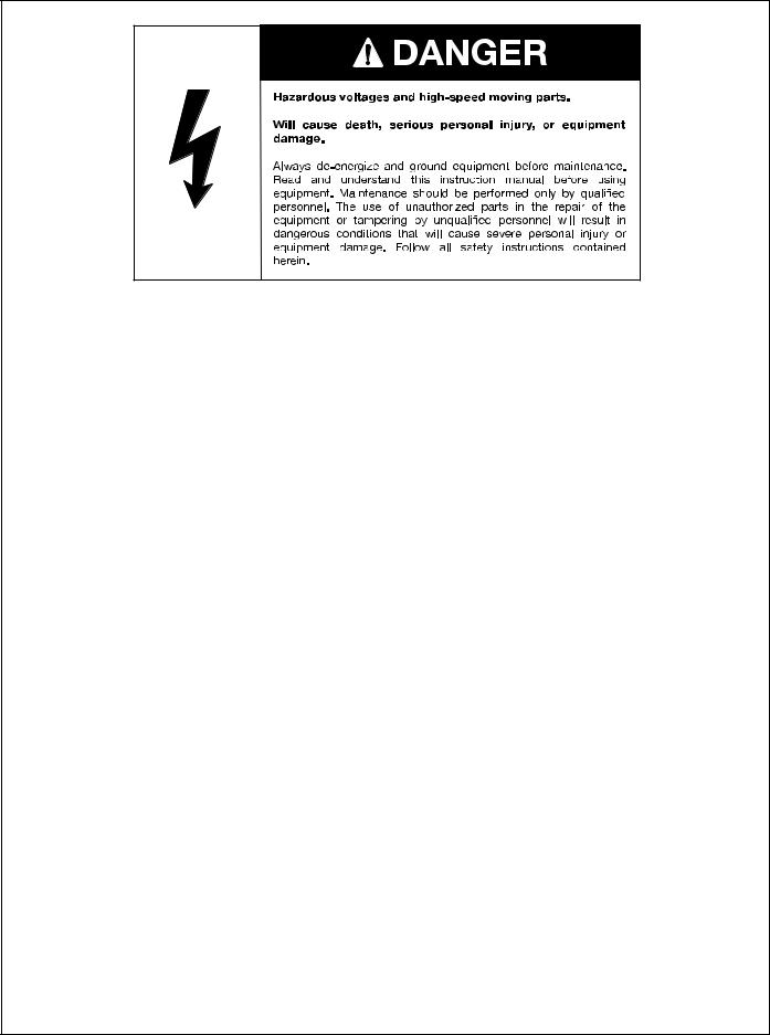
•Danger - indicates an imminently hazardous situation which, if not avoided, will result in death or serious injury
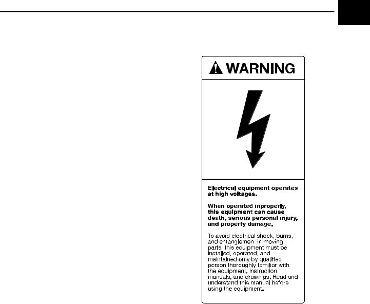
•Warning - indicates a potentially hazardous situation which, if not avoided, could result in death or serious injury
•Caution - indicates a potentially hazardous situation which, if not avoided, could result in moderate or minor injury
Required Procedures
In addition to normal safety practices, user personnel must adhere to the following procedures:
1.Always work on de-energized equipment. Always deenergize a breaker or contactor, and remove it from the equipment before performing any tests, maintenance, or repair.
2.Always perform maintenance on equipment employing springs after the spring-charged mechanisms are discharged.
3.Always let an interlock device or safety mechanism perform its function without forcing or defeating the device.
Field Service Operation
Siemens can provide competent, well-trained Field Service Representatives to provide technical guidance and advisory assistance for the installation, overhaul, repair, and maintenance of Siemens equipment, processes, and systems. Contact regional service centers, sales offices, or the factory for details.
1.3 Product Description
The ISGS relay is a general purpose, multifunction, micropro- cessor-based protective relay. It performs protection, metering, and monitoring for three phase current transformer (CT) inputs and one ground CT input.
The ISGS relay provides two breaker tripping contacts and one relay disabled (alarm) contact. The relay disabled contact is a normally closed contact which opens when the relay is functioning properly.
1.3.1Standard Configuration
The ISGS relay base unit includes the following standard protection, metering, and monitoring features:
•Instantaneous Phase Overcurrent (50) protection
•Instantaneous Neutral or Ground Overcurrent (50N) protection
•Phase Time Overcurrent (51) protection
•Neutral or Ground Time Overcurrent (51N) protection
|
|
|
|
|
|
ISGS |
|
|
|
|
|
|
System |
|
|
|
|
|
|
Pickup |
|
|
|
|
|
|
Trip |
|
Pass |
Direct |
7 |
8 |
9 |
|
|
word |
Addr |
||||
Target |
Target |
Trip |
4 |
5 |
6 |
|
Reset |
Reset |
Log |
||||
|
|
|
|
1 |
2 |
3 |
|
|
|
|
|
0 |
-/+ |
|
|
|
F |
Pass |
∞ Enter |
|
|
|
|
word |
|||
|
|
|
|
Yes |
No |
|
|
|
|
|
|
Data Port |
|
|
|
ISGS |
LR |
|
|
|
|
Cat# C552-100V-5D0-000 |
|
|
|
||
|
VPSn 120VAC/250VDC |
|
|
|
||
|
IPH |
5A |
IC 5A |
|
|
|
|
Ser# |
Beta05HW15W2.XX |
|
|
|
|
Figure 1.1 Intelligent SwitchGear System (ISGS) Relay
•Nine selectable time overcurrent curves and one custom curve
•Breaker Failure (50BF) protection
•Phase and neutral current as well as average current metering
•Minimum/maximum logs for storing metering data
•Waveform capture
•Trip log for recording information on last eight trip events
•Event log for monitoring and recording relay functions for status changes
•2-line by 16-character liquid crystal display (LCD) for viewing measured data
•26-key membrane keypad for local access and selected manual data entry.
•LED indicators for general relay status information
•Standard RS-232 communications port for local access to all parameter settings using a personal computer (PC) and Wisdom™ software
•Password security
The ISGS relay is supplied in an M1-size drawout case with dust tight front cover. The case is compatible with XLA connecting plugs that are commonly used to test relays.
2 |
Siemens Energy & Automation, Inc. |

Introduction  1
1
1.3.2Optional Configurations
The ISGS relay is a dynamic, feature-rich device that can be used in numerous industrial and utility applications. It allows the addition of options or configuration changes at any time without discarding the basic hardware.
There are four optional configurations that can be added to the ISGS relay base unit.
Metering
Adding metering to the ISGS relay provides the relay with three inputs for the connection of VTs. Each input can be set from 100 V to 120 V. These inputs extend metering capabilities as follows:
•Rms and average rms voltages
•Active and apparent power
•Kilowatt demand and kilowatt demand hours
•Power factor
•Frequency
The installation of the voltage input card now also allows the setting of these protective functions:
•High-Set Instantaneous Phase Overcurrent (50HS)
•High-Set Instantaneous Neutral or Ground Overcurrent (50HSN)
The metering option is also a prerequisite for the next two options: additional protective functions and remote communications.
Additional Protective Functions
For an ISGS relay with the metering option installed, the following additional protective functions offer a powerful extension of its protection capabilities:
•Under/Overvoltage (27/59)
•Phase Sequence Voltage (47)
•Negative Sequence Voltage (47N)
•Directional Time Overcurrent (67/67N)
•Over/Underfrequency (81U/O)
Communications
Adding communications to the ISGS relay provides the relay with an RS-485 port. Using the SEAbus™ communications protocol, this port allows remote communications and control via the ACCESS™ electrical distribution and communication system (ACCESS system).
Communications allows configuration, measurement, and protection functions to be performed or reviewed easily from a remote location using Wisdom software.
1.4 Wisdom Software
While it is possible to completely set up and configure the ISGS relay using the front panel keyboard and display, the free Wisdom software package provided with the relay reduces the complexity of configuring the relay, reading metered values, and retrieving stored data. For more information on Wisdom software, refer to Chapter 8.
Siemens Energy & Automation, Inc. |
3 |

1Introduction
1.5 |
Technical Specifications |
||||||||||||||
|
|
|
|
|
|
|
|
|
|
|
|
|
|
|
|
|
Applicable Standards |
||||||||||||||
ANSI / IEEE C37.90-1989 |
IEEE Standard Relays and Relay |
||||||||||||||
|
|
Systems Associated With Elec- |
|||||||||||||
|
|
tric Power Apparatus |
|||||||||||||
|
|
|
|
|
|
|
|
|
|
|
|
|
|
|
|
IEC 255-4 |
Single Input Energizing Quantity |
||||||||||||||
|
|
Measuring Relays With Depen- |
|||||||||||||
|
|
dent or Independent Time |
|||||||||||||
|
|
|
|
|
|
|
|
|
|
|
|
|
|
|
|
|
General Technical Data |
||||||||||||||
Operating ambient temperature |
-20°C to +55°C (-4°F to +131°F) |
||||||||||||||
|
|
|
|
|
|
|
|
|
|
|
|
|
|
|
|
Storage temperature |
-40°Cto+75°C (-40°F to+167°F) |
||||||||||||||
|
|
|
|
|
|
|
|
|
|
|
|
|
|
|
|
Relative humidity |
The average relative humidity |
||||||||||||||
|
|
may be up to 55% outside of |
|||||||||||||
|
|
enclosure for temperatures up to |
|||||||||||||
|
|
40°C, with excursions up to |
|||||||||||||
|
|
95% for a maximum of 96 |
|||||||||||||
|
|
hours, without condensation. |
|||||||||||||
|
|
|
|
|
|
|
|
|
|
|
|
|
|
|
|
Altitude |
< 1500 meters |
||||||||||||||
|
|
|
|
|
|
|
|
|
|
|
|
|
|
|
|
Frequency |
50 Hz or 60 Hz, software select- |
||||||||||||||
|
|
able |
|||||||||||||
|
|
|
|
|
|
|
|
|
|
|
|
|
|
|
|
|
Power Supply AC/DC |
||||||||||||||
DC |
Rated voltages |
48 V (19-56 V), |
|||||||||||||
|
|
125 V (46-144 V), |
|||||||||||||
|
|
250 V (92-288 V) |
|||||||||||||
|
|
|
|
|
|
|
|
|
|
|
|
|
|
|
|
|
Permissible ripple |
<10% |
|
|
|
|
|
|
|
|
|
|
|||
|
|
|
|
|
|
|
|
|
|
|
|
|
|
|
|
AC |
Rated voltage |
120 V rms (102-132 V, 50-60 Hz) |
|||||||||||||
|
|
|
|
|
|
|
|
|
|
|
|
|
|
|
|
|
Power consumption |
<15W |
|||||||||||||
|
|
|
|
|
|
|
|
|
|
|
|
|
|
|
|
|
Input Circuit Ratings |
||||||||||||||
Rated current (In) |
1 or 5 A, independently for |
||||||||||||||
|
|
phase and ground inputs |
|||||||||||||
|
|
|
|
|
|
|
|
|
|
|
|
|
|
|
|
Maximum input current |
4 x In continuous |
||||||||||||||
|
|
10 x In for 10 s |
|||||||||||||
|
|
100 x In for 1 s |
|||||||||||||
CT burden |
<0.1 VA for 1A CT |
||||||||||||||
|
|
|
|
|
|
|
|
|
|
|
|
|
|
|
|
|
|
<0.5 VA for 5A CT |
|||||||||||||
|
|
|
|
|
|
|
|
|
|
|
|
|
|
|
|
Rated voltage (Vn) |
115 or 120 volts |
||||||||||||||
Maximum input voltage |
for measurement: 1.25 x Vn |
||||||||||||||
|
|
MOV protected at: 2.5 x Vn |
|||||||||||||
VT burden |
150kW |
||||||||||||||
|
|
|
|
|
|
|
|
|
|
|
|
|
|
|
|
|
Trip Circuit |
||||||||||||||
Tripping relays |
2 or 3 |
||||||||||||||
|
|
|
|
|
|
|
|
|
|
|
|
|
|
|
|
Contact configuration |
|
|
|
|
|
|
|
|
|
|
|
|
|
|
|
(Trip 1, Trip 2, Trip 3) |
|
|
|
|
|
|
|
|
|
|
|
|
|
|
|
|
|
|
|
|
|
|
|
|
|
|
|
|
|
||
|
|
|
|
|
|
|
|
|
|
|
|
|
|
|
|
|
|
|
|
|
|
|
|
|
|
|
|
|
|
|
|
|
|
|
|
|
|
|
|
|
|
|
|
|
|
|
|
|
|
|
|
|
|
|
|
|
|
|
|
|
|
|
|
Contact rating |
IEEE/ANSI C37.90-1989, Sec- |
||||||||||||||
|
|
tion 6.7 (Make and carry 30 A for |
|||||||||||||
|
|
at least 2000 duty cycles, resis- |
|||||||||||||
|
|
tive load, interrupted by indepen- |
|||||||||||||
|
|
dent means. Duty cycle: |
|||||||||||||
|
|
200 ms on, 15 s off, 250 V) |
|||||||||||||
|
|
|
|
|
|
|
|
|
|
|
|
|
|
|
|
Trip Circuit (continued)
Binary output contacts |
2 x N.O. (independent, |
(BO1 and BO2) |
not rated for tripping) |
|
|
Maximum switching voltage |
300 VDC, 250 VAC |
|
|
Maximum switching current |
8 A |
|
|
Maximum switching capac- |
DC: voltage dependent; |
ity (for currents not inter- |
50 W at V ³70 VDC |
rupted by independent |
100 W at 48 VDC |
means) |
270 W at 35 VDC |
|
AC: 2000 VA |
|
|
Trip source monitor |
215 mA for 48 VDC supply |
|
63 mA for 125 VDC supply |
|
36 mA for 250 VDC supply |
|
Source quality checked approxi- |
|
mately every 4 minutes |
|
|
Isolation |
|
Applicable standards |
ANSI/IEEE C37.90-1989, |
|
IEC 255-4, IEC 255-5 |
|
|
Between all circuits (except |
2 kV rms, 50/60 Hz, 1 minute |
communications interfaces, ana- |
|
log inputs and outputs) and |
|
ground, and between these cir- |
|
cuits. |
|
|
|
Between communications inter- |
500 VDC, 1 minute |
faces, analog inputs and outputs |
|
and ground, and between these |
|
circuits |
|
|
|
Across open contacts rated for |
1500 V rms, 50/60 Hz, 1 minute |
tripping |
|
|
|
Across open contacts not rated |
1000 V rms, 50/60 Hz, 1 minute |
for tripping |
|
|
|
Impulse |
|
Applicable standards |
IEC 255-4, IEC 255-5 |
|
|
For all circuits (except communi- |
class 3, 5 kV, 1.2/50 ms, 0.5 J |
cations interfaces, analog |
|
inputs and outputs), transverse |
|
and common mode |
|
|
|
RS-485 and local communica- |
class 1, 0 kV |
tions interfaces, analog I/Os |
|
|
|
Electrostatic Discharge |
|
Applicable standards |
IEC 801-2 (test without cover) |
|
|
Contact discharge |
class 3, 6 kV |
|
|
Air discharge |
class 3, 8 kV |
|
|
Surge Withstand Capability |
|
Applicable standards |
ANSI/IEEE C37.90-1989, |
|
IEC 255-4, IEC 255-22-1, |
|
IEC 41B (CO) 53 |
|
|
For all circuits except communi- |
ANSI: Oscillatory and Fast Tran- |
cations interfaces, analog |
sient, transverse and common |
inputs and outputs |
mode |
|
IEC: Class 3, 2.5 kV |
|
|
For RS-485 interface, analog |
IEC: Class 1, 0.5 kV |
inputs and outputs |
|
|
|
Electromagnetic Field |
|
Applicable standards |
ANSI/IEEE C37.90.2 |
|
|
All six faces |
10 V/m (+100%, -0%), |
|
2-1000 MHz |
4 |
Siemens Energy & Automation, Inc. |
Installation
2 Installation |
2.3 Mounting |
|
2 |
This chapter explains the installation of the ISGS relay and |
The ISGS relay is typically installed in a switchgear unit or |
||
includes procedures for unpacking, storing, mounting, and |
relay panel. The required panel opening and a side view of |
|
|
|
|
||
wiring the relay. Prior to installation, ensure that the system |
the relay are shown in Figure 2.2. |
|
|
power is off and that you have all required tools and test equipment available.
|
|
5.69 |
|
2.1 |
Unpacking |
(144.5) |
4X .25 (6.4) DIA |
2.84 |
|||
|
|
(72.1) |
|
Upon receipt of the relay, inspect the carton for signs of dam- |
|
|
|
age. If the carton has been opened or damaged, carefully |
|
|
|
inspect and verify the contents against the packing list. If |
|
|
|
pieces are missing or damaged, contact the shipping agent |
|
|
|
or your Siemens representative. Refer to Figure 2.1 to iden- |
|
|
|
tify the different parts of the relay. |
|
|
|
|
Note: To avoid damage to the relay, transport or |
|
|
|
store the relay in the original packing mate- |
14.63 |
|
|
rial. Always transport the cradle assembly |
14.25 |
|
|
(371.5) |
||
|
(362.0) |
||
|
inside the case. |
|
|
|
|
|
|
. |
|
|
|
|
|
7.31 |
7.13 |
|
|
(181.0) |
|
|
|
(185.7) |
|
|
|
|
|
|
|
3.03 |
|
|
|
(77.0) |
|
|
|
6.06 |
|
|
|
(154.0) |
|
|
|
6.19 |
.63 |
|
|
(157.2) |
(16.0) |
|
|
|
10-32 |
|
|
|
SCREWS |
Figure 2.1 Case, Cradle, Paddles, and Cover of ISGS Relay |
.31 |
|
|
|
|
(7.9) |
|
2.2 |
Storing |
7.06 |
|
(179.4) |
|
||
Extended storage of the relay should adhere to the following |
|
|
|
guidelines: |
|
|
|
• Store the relay in a clean, dry location in the original |
|
|
|
|
packing material |
|
|
• Storage temperature range is -40°F to +167°F |
|
|
|
|
(-40°C to +75°C) |
|
|
|
|
7.06 |
|
|
|
(179.4) |
|
|
Note: This device contains electrolytic capacitors, |
|
|
|
which can degrade over time when stored |
.31 |
|
|
at temperatures over 86°F (30°C). Take care |
|
|
|
(7.9) |
10-32 |
|
|
not to store the relay at high temperatures |
|
|
|
|
SCREWS |
|
|
for extended periods. |
|
|
|
|
.63 |
|
After extended storage, connect the relay to its auxiliary volt- |
(16.0) |
|
|
MOUNTING PANEL |
|
||
age source for one or two days prior to taking it into actual |
|
|
|
service. This serves to regenerate the electrolytic capacitors |
Figure 2.2 Mounting Dimensions |
|
|
of the auxiliary supply. |
|
||
|
|
||
Siemens Energy & Automation, Inc. |
5 |
Installation
2 |
Mount the relay using the following steps. |
IMPORTANT: |
|
Any unused terminals must remain discon- |
|
1. Install the relay M1-type case in the panel opening on |
nected. They are for factory use only. |
|
|
the switchgear equipment. |
|
|
|
2.Connect the case ground to the terminal lug on the back of the M1-type case as shown in Figure 2.3.
3.Wire as described in Section 2.4.
Use toothed washers to ensure solid metal contact through paint of cover and panel
Case ground, #12 or braided cable to good cubicle ground, as short as possible
Figure 2.3 Case Grounding
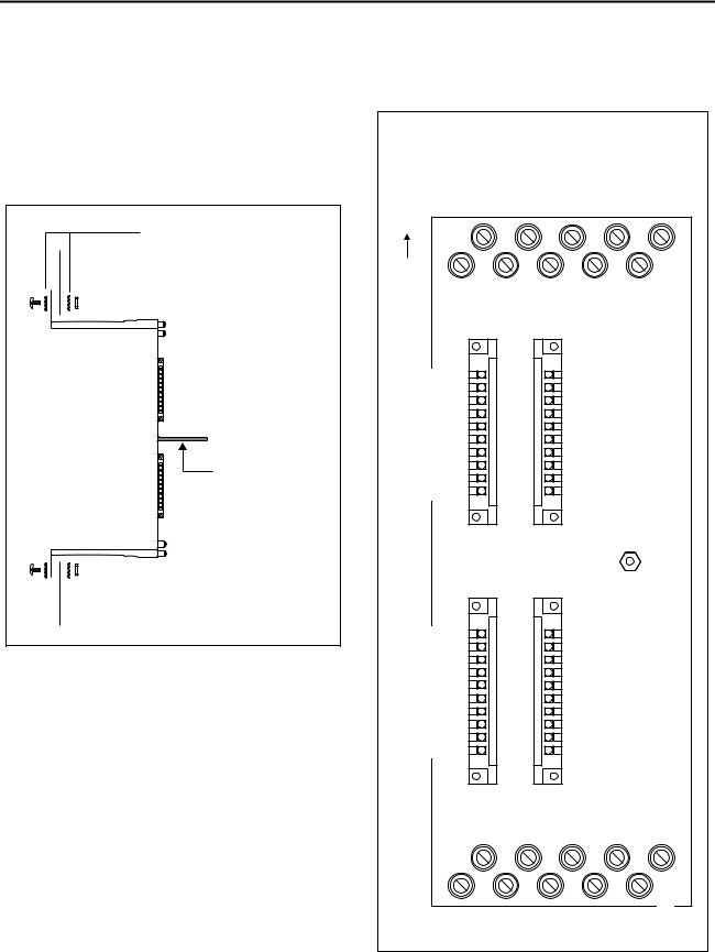
2.4 Wiring
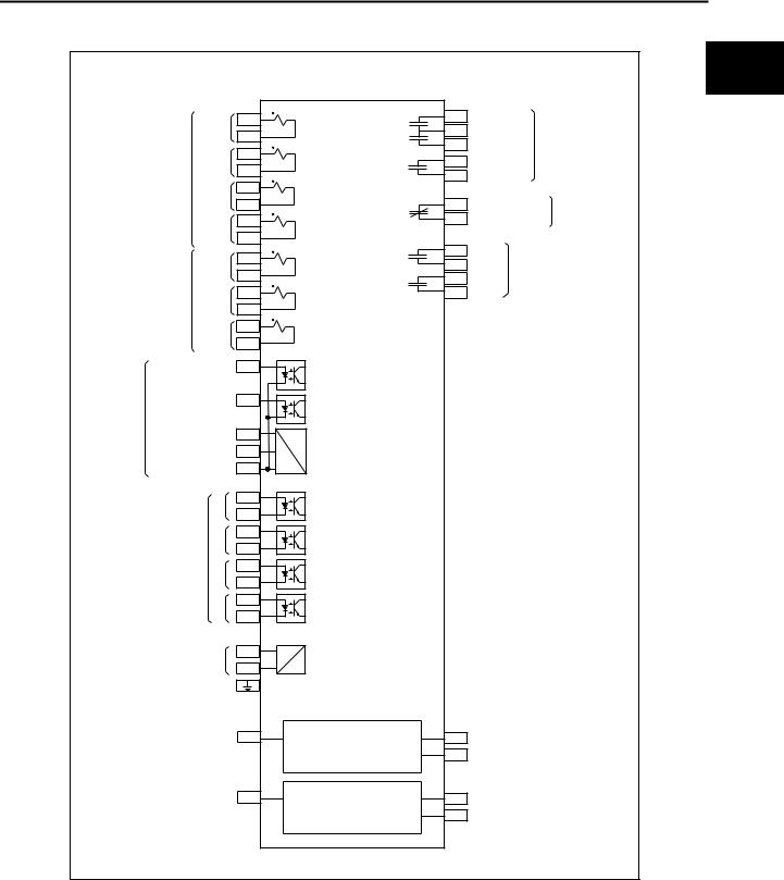
Wire the ISGS relay after the case is installed. Connect the wiring to the applicable terminals to support the desired features. Refer to Figure 2.4 for terminal locations. Figure 2.5 shows the internal connections of the ISGS relay. To avoid injury to personnel or the equipment, perform power connections after all other wiring has been completed.
Assure that all power is off before performing any wiring. Terminals 1 through 20 accept ring-tongue or forked spade terminals and are suitable for 14 AWG to 10 AWG wire. Terminals 21 through 60 are for directly inserting the appropriate wire and are suitable for 22 AWG to 14 AWG wire.
Communications connections made to terminals 48 to 50 require shielded twisted pair wire.
|
RelayDisabled2 |
RelayDisabled1 |
ImpedanceSense |
ImpedanceSource |
GroundMonitor |
BITrip |
BIBSwitch |
PowerInput+ |
PowerInput- |
Trip2 |
|
Top |
19 |
17 |
|
15 |
|
|
13 |
|
11 |
|
|
20 |
|
18 |
16 |
14 |
12 |
|
|
||||
BI1A |
21 |
|
|
|
|
41 |
|
VT1+ |
|
|
|
BI1B |
22 |
|
|
|
|
42 |
|
VT1- |
|
|
|
BI2A |
23 |
|
|
|
|
43 |
|
VT2+ |
|
|
|
BI2B |
24 |
|
|
|
|
44 |
|
VT2- |
|
|
|
BI3A |
25 |
|
|
|
|
45 |
|
VT3+ |
|
|
|
BI3B |
26 |
|
|
|
|
46 |
|
VT3- |
|
|
|
BI4A |
27 |
|
|
|
|
47 |
|
NC (unused) |
|
|
|
BI4B |
28 |
|
|
|
|
48 |
|
SEAbus Signal + |
|
||
Trip 3A |
29 |
|
|
|
|
49 |
|
SEAbus Signal - |
|
||
Trip 3B |
30 |
|
|
|
|
50 |
|
SEAbus Ref |
|
|
|
|
|
|
|
|
Case Ground |
|
|
|
|||
BO1A |
31 |
|
|
|
|
|
|
|
|
|
|
BO1B |
32 |
|
|
|
|
|
|
|
|
|
|
BO2A |
33 |
|
|
|
|
|
|
|
|
|
|
BO2B |
34 |
|
|
|
|
|
|
|
|
|
|
AI1+ |
35 |
|
|
|
|
|
|
|
|
|
|
AI1- |
36 |
|
|
|
|
|
|
|
|
|
|
AI2+ |
37 |
|
|
|
|
|
|
|
|
|
|
AI2- |
38 |
|
|
|
|
|
|
|
|
|
|
AO1+ |
39 |
|
|
|
|
|
|
|
|
|
|
AO1- |
40 |
|
|
|
|
|
|
|
|
|
|
|
|
9 |
7 |
|
5 |
|
|
3 |
|
1 |
|
10 |
|
8 |
|
6 |
|
4 |
2 |
|
TripCommon |
||
|
CTN-2 |
CTN-1* |
CT3-2 |
CT3-1* |
CT2-2 |
CT2-1* |
|
CT1-2 |
CT1-1* |
Trip1 |
|
CT connections should be made with the polarity end of the |
Figure 2.4 Terminal Locations |
|
CT connected to current terminal marked with an asterisk (*). |
||
|
6 |
Siemens Energy & Automation, Inc. |
|
|
|
|
|
|
|
|
|
|
|
Installation |
|
|
|
|
|
|
|
ISGS |
|
|
|
2 |
|
|
|
|
|
|
|
|
|
|
|
|
|
|
CT 1-1 |
|
3 |
|
2 |
Trip 1 |
Trip |
|
||
|
|
|
|
1 |
Trip Common |
|
|||||
|
|
CT 1-2 |
|
4 |
|
Relays |
|||||
|
|
|
|
11 |
Trip 2 |
|
|
||||
|
|
CT 2-1 |
|
5 |
|
|
|
||||
|
|
|
|
29 |
|
|
|
||||
|
|
CT 2-2 |
|
6 |
|
Trip 3 |
|
|
|||
|
|
|
|
30 |
|
|
|
||||
|
|
|
|
|
|
|
|
|
|
|
|
Current |
CT 3-1 |
|
7 |
|
|
|
|
|
|||
Input |
CT 3-2 |
|
8 |
|
19 |
Relay Disabled 1 |
Relay Disabled |
||||
|
|
CT N-1 |
9 |
|
20 |
Relay Disabled 2 |
Alarm Contact |
||||
|
|
CT N-2 |
10 |
|
|
|
|
|
|||
|
|
|
VT 1+ |
41 |
|
31 |
BO 1 |
|
|
||
|
|
|
|
32 |
|
|
|||||
|
|
|
|
|
|
|
|
Binary |
|
|
|
|
|
|
VT 1- |
|
42 |
|
33 |
Outputs |
|
||
|
Voltage |
|
VT 2+ |
43 |
|
34 |
BO 2 |
|
|
||
|
|
|
|
|
|
||||||
|
Input |
|
VT 2- |
|
44 |
|
|
|
|
|
|
|
|
|
|
|
|
|
|
|
|||
|
|
|
VT 3+ |
45 |
|
|
|
|
|
||
|
|
|
VT 3- |
|
46 |
|
|
|
|
|
|
|
BI B Switch |
|
|
14 |
|
|
|
|
|
||
Breaker and |
BI Trip |
|
|
|
|
15 |
|
|
|
|
|
Trip Source |
|
|
|
|
|
|
|
|
|
|
|
Monitor |
Impedance Source |
17 |
|
|
|
|
|
||||
|
|
|
|
|
|
||||||
|
Impedance Sense |
18 |
|
|
|
|
|
||||
|
Ground Monitor |
|
16 |
|
|
|
|
|
|||
|
|
|
|
1 |
+ |
21 |
|
|
|
|
|
|
|
|
|
- |
22 |
|
|
|
|
|
|
|
|
|
|
2 |
+ |
23 |
|
|
|
|
|
|
Binary |
|
- |
24 |
|
|
|
|
|
||
|
|
|
+ |
25 |
|
|
|
|
|
||
|
Input |
|
|
3 |
|
|
|
|
|
||
|
|
|
|
- |
26 |
|
|
|
|
|
|
|
|
|
|
4 |
+ |
27 |
|
|
|
|
|
|
|
|
|
- |
28 |
|
|
|
|
|
|
|
Power |
|
VH |
+ 13 |
DC |
|
|
|
|
||
|
Supply |
- |
12 |
DC |
|
|
|
|
|||
|
|
|
|
|
|
||||||
|
|
|
|
|
|
|
|
|
|||
|
Communications |
|
|
Communications |
|
|
|||||
|
In |
|
|
|
|
|
|
|
Out |
|
|
|
|
Data + |
48 |
RS-485 SEAbus |
49 |
Data - |
|
|
|||
|
|
|
|
|
|
|
50 |
Reference |
|
|
|
|
|
|
|
|
|
|
|
|
|
||
|
|
RxD |
|
(3) |
RS-232 |
(2) |
TxD |
|
|
||
|
|
|
|
|
|
|
Front Panel |
(7) |
Reference |
|
|
|
|
|
|
|
|
|
|
|
|
||
|
|
|
|
|
|
|
|
|
Ground |
|
|
Figure 2.5 Internal Connections
Note: The relay disabled contact should be wired to plant-wide distributed control system or external alarm.
Siemens Energy & Automation, Inc. |
7 |

Installation
2 |
2.5 |
Communications |
2.6 |
|
Cradle Assembly |
|
The ISGS relay must be connected to a host computer in |
Some of the setup and maintenance procedures in this man- |
|||||
|
order for it to communicate with other devices. The relay |
ual require removal of the relay cradle assembly from the |
||||
|
||||||
|
supports both RS-232 and RS-485 (optional) data inter- |
drawout case. Use the following instructions for the proper |
||||
|
faces. The use of either of these data interfaces will allow the |
removal and insertion of the cradle assembly. |
||||
|
same level of access to the system as the front panel key- |
|
|
|
|
|
|
pad, but configuration through communications does not |
|
|
IMPORTANT: |
||
|
require a password. |
|
|
The relay module contains CMOS circuits. Electro- |
||
|
|
|
|
|
static discharges into or around the relay cradle or |
|
|
The next section describes the connection to the interfaces. |
|
|
any of its components must be avoided. Use |
||
|
For more information about operating the ISGS relay via the |
|
|
grounding straps or touch a grounded metal sur- |
||
|
data interfaces, refer to the documentation for the communi- |
|
|
face before handling the relay cradle. |
||
|
cations software, such as WinPM™ or Wisdom. Keypad |
|
|
|
|
|
|
operations are described in Chapter 3. |
2.6.1 |
Removing |
|||
|
2.5.1 PC Communications (RS-232) |
Use the following procedure to remove the cradle assembly |
||||
|
from the case: |
|||||
|
|
|
||||
|
The RS-232 interface (front port) is intended only for short- |
|
|
|
|
|
|
term connections to a portable computer. Use this interface |
1. |
|
Remove the relay case front cover. |
||
|
to perform initial setup or to read the ISGS relay data logs or |
|
|
|
|
|
|
waveform buffers using an appropriate software program. To |
2. |
Remove the top and bottom connecting plugs |
|||
|
connect your PC to the front port, follow these instructions: |
|
|
(paddles). |
||
|
1. |
Remove the relay case front cover. |
3. |
Loosen the cradle assembly by pulling the top release |
||
|
|
|
|
|
lever to the left and the bottom release lever to the right |
|
|
2. Locate the RS-232 connector on the front panel of the |
|
|
until the assembly ejects from the case. |
||
|
|
cradle assembly. |
|
|
|
|
|
|
|
4. |
Grasp the cradle assembly by the edges of the front |
||
|
3. Connect the PC to the front panel RS-232 port using a |
|
|
panel and pull it out of the drawout case. |
||
|
|
standard DB-9 serial port connection cable (DB-9 male |
|
|
|
|
|
|
to DB-9 female or DB-25 female depending on the type |
5. |
Place the cradle assembly on an anti-electrostatic sur- |
||
|
|
of port on the computer). This connection does not |
|
|
face and perform the desired work. |
|
|
|
require the use of special adapters or a null-modem |
|
|
|
|
|
|
cable. |
2.6.2 |
Inserting |
||
|
2.5.2 Network Communications (RS-485) |
Use the following procedure to insert the cradle assembly |
||||
|
into the drawout case: |
|||||
|
|
|
||||
|
The optional RS-485 interface (rear port) allows remote com- |
|
|
|
|
|
|
munication over a shielded twisted pair wire at distances of |
1. |
Insert the cradle assembly until the release levers come |
|||
|
up to 4000 feet. Use this interface together with an appropri- |
|
|
in contact with the protrusions on the case. |
||
|
ate software program for remote monitoring and control of |
|
|
|
|
|
|
the ISGS relay. |
2. |
Position the top and bottom release levers until the slots |
|||
|
|
|
|
|
on the levers align with the protrusions on the case. |
|
|
To connect the ISGS relay to your communications system, |
|
|
|
|
|
|
follow these instructions: |
3. |
Use the release levers to finish inserting the cradle |
|||
|
|
|
|
|
assembly into the case. Apply pressure to the cradle |
|
|
1. Locate the RS-485 connector on the rear of the M1 |
|
|
assembly front panel until the assembly fully seats in the |
||
|
|
case. |
|
|
case. |
|
|
2. Use shielded twisted pair wire to connect pins 48, 49, |
4. |
|
Insert the top and bottom paddles. |
||
|
|
and 50 to your electrical distribution system. |
|
|
|
|
|
|
|
5. |
Check for proper insertion of the cradle assembly by |
||
|
To connect the ISGS relay to your PC via the rear port |
|
|
seeing if the expected measured values are observed on |
||
|
|
|
|
|
the relay display. |
|
•directly, use an RS-232 to RS-485 converter.
6. Install the front cover.
•via modem, use an RS-232 to RS-485 converter and a null modem.
8 |
Siemens Energy & Automation, Inc. |
User Interface
3 User Interface
Operation, parameter selection, and control of the ISGS relay are performed using the front panel controls and indicators. They consist of a 26-key membrane keypad, a 2-line by 16-character liquid crystal display (LCD), three light-emitting diodes (LEDs), and the front port.
3.1 Keypad
The relay can be controlled via the keypad, the front port, or the optional rear port. This manual covers only keypad operations. For information about communicating with the ISGS relay via the data ports, refer to the documentation supplied with the communications software (WinPM or Wisdom).
The ISGS relay keypad allows access to any relay information or function for display or parameter changes where applicable. The keypad consists of 26 keys. Table 3.1 provides a detailed description of each key type.
To access relay information or functions for display or modification, use the Arrow keys to scroll through relay addresses or use the Direct Addr key and the specific address number to go directly to the information or function.
Use the Double Arrow keys to scroll through the address blocks and use the Single Arrow keys to scroll within an address block.
3.2 Indicators
The indicators on the front panel display consist of three LEDs and a two-line LCD.
3.2.1LEDs
The LED indicators are used to provide general status information, which alerts the operator to an event or problem and prompts the operator to use the LCD to review the logs for more detailed information. The three LEDs and their functions are listed below.
LED |
Color |
Function |
|
|
|
System |
Green |
Denotes the relay is operating properly |
|
|
(always on when relay is in service). |
|
|
|
Pickup |
Red |
Denotes a protective function is in |
|
|
pickup. |
|
|
|
Trip |
Red |
Denotes a protective function or |
|
|
remote command has initiated a trip. |
|
|
|
Both the Pickup and the System LED operate automatically and do not require a reset.
•The System LED remains on as long as power is applied and the relay is functioning properly.
•The Pickup LED is illuminated as long as a protective function is in pickup.
.
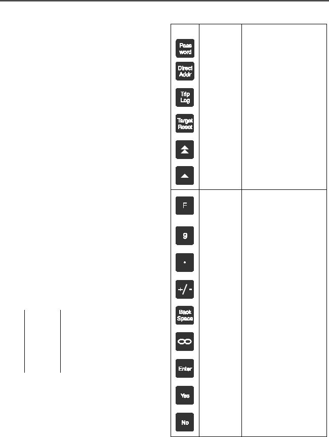
Key |
Name |
Function |
|
|
|
|
|
|
|
|
Password |
Accesses the password function, |
|
|
|
|
which is required for programming |
|
|
|
|
relay settings. |
|
|
|
|
|
|
|
|
|
|
|
3 |
|
Direct Addr |
Allows direct entry of addresses. |
||
|
|
|
||
|
|
|
|
|
|
l |
|
|
|
|
|
|
|
|
|
Trip Log |
Displays the trip log. |
|
|
|
|
|
|
|
|
Target Reset |
Resets the Trip LED. |
|
|
|
|
|
|
|
|
Double Arrow |
Scrolls through the address |
|
|
|
|
blocks. |
|
|
|
|
|
|
|
|
Single Arrow |
Scrolls through the addresses |
|
|
|
|
within an address block. |
|
|
FSaves new settings when followed by Enter, enters or exits subad-
|
dress level, or switches to alter- |
|
nate parameter set when followed |
|
by 1 or 2 and Enter. |
|
|
Numeric |
Used to enter an address number |
|
after pressing Direct Addr, or to |
|
enter a numeric setting. |
|
|
Decimal Point |
Indicates a decimal point or the |
|
separation between month, day, |
|
and year, or between hours, min- |
|
utes, and seconds. |
|
|
Plus/Minus |
Toggles between positive and |
|
negative values. |
|
|
Backspace |
Deletes one character to the left or |
|
selects backwards. |
|
|
Infinity |
Programs the setting to the high- |
|
est possible value. |
|
|
Enter |
Chooses the setting option, enters |
|
a setting value, or confirms the |
|
address entered after pressing |
|
Direct Addr. |
|
|
Yes |
Accepts the displayed setting, or |
|
replies “yes” to the displayed |
|
prompt. |
|
|
No |
Rejects the displayed setting, |
|
allows entry of a numeric setting, |
|
replies “No” to the displayed |
|
prompt, or selects forward. |
Table 3.1 Front Panel Keys
Siemens Energy & Automation, Inc. |
9 |

User Interface
The Trip LED is illuminated until the Target Reset key is depressed. Reset the Trip LED by momentarily depressing the Target Reset key.
3 |
Note: If the Trip LED is on and power is removed, it |
|
will still be set to on when power is restored. |
||
|
||
|
3.2.2 LCD |
|
|
The two-line by sixteen-character LCD allows the viewing of parameters, measured data, and keypad entries. The LCD also displays messages returned by events such as a relay going into pickup.
Whenever a relay goes into pickup, in addition to lighting the pickup LED, the LCD shows a message that indicates which protection element is in pickup. A pickup message is displayed as follows:
|
PICKUP FFF Pxxxx |
|
|
MM/DD hh:mm:ss |
|
|
|
|
In this message |
||
FFF |
is the two or three character ANSI pro- |
|
|
tection code number, for example, 50, |
|
|
or 50N. |
|
xxxxis a sequence of the characters 1, 2, 3, and/or N, indicating which phase or combination of phases and neutral have picked up.
MM/DD hh:mm:ss is the date and time of the event.
These messages are displayed until superseded by another pickup, a trip message, a target reset, or a request by the operator to display other information.
3.3 Password Protection
A password should be used to prevent any accidental or unauthorized parameter changes. While relay information can be accessed for display without a password, all changes to parameter settings require a user password.
Note: The ISGS relay is not password protected when making parameter changes through Wisdom software.
The ISGS relay offers three password protected access levels:
Level 1 consists of simple settings such as all protective and setpoint settings that do not cause a reset. These simple settings include communications and time and date settings.
Level 2 consists of protective function settings such as CT and VT ratios, the changing of which can cause a device reset.
Level 3 includes additional access to all matrixing, the changing of which can cause a device reset.
Password configuration is described in Section 9.4.
To access any password protected information or function, either first enter the password (up to five digits) and then go to the desired address, or first access the address block and then enter the password as described in the following steps:
1.Press the Password key. The password dialog box appears.
Password:
2.Enter a password (00000 to 99999) using the number keys from the keypad. The LCD displays each digit entered as an @ symbol.
Password:
@@@@@
3.Press the Enter key after completing the entry.
4.If a correct password has been entered, the dialog box displays a confirmation message that depends on the level password that was entered.
Password:
User PW Three OK
For a level 1 or level 2 password, the word “Three” in the illustration above would be replaced by “One” and “Two,” respectively.
If the wrong password has been entered, the dialog box displays the following message:
Password:
Rejected
5.When the confirmation message appears, press the Enter key. This action returns the display that was in use before entering the password.
For example, if the address block of the parameter to be changed was displayed prior to entering the password, the display returns to this address block and the device is ready to accept changes.
10 |
Siemens Energy & Automation, Inc. |

User Interface
3.4 Menu
The ISGS relay menu (or memory map) is organized in a hierarchical structure that is made up of address blocks and addresses. The first level consists of address blocks. Each address block represents one complete function or two related functions and is identified by a unique four-digit number ending in two zeros (for example, 1500). Refer to
Figure 3.1.
The second level consists of individual addresses confined to an address block. Each address represents a part of a func- tion—the changeable parameter—or the measured value of a displayed parameter. The parameter is identified by a unique four-digit number that consists of the first two digits of the address block and two digits indicating the parameter’s number within the address block (for example, 1502). Refer to Figure 3.1.
Block |
Function |
Address |
Parameter |
|
|
|
|
A1500 |
Instantaneous |
1501 |
Function 50 |
|
Phase Overcurrent |
1502 |
Pickup 50 |
|
(50) |
1504 |
Delay 50 |
|
|
1510 |
Freeze Wfm 1 50 |
|
|
1511 |
Freeze Wfm 2 50 |
|
|
1512 |
Block 50 |
|
High-Set Instanta- |
1551 |
Function 50HS |
|
neous Phase Over- |
1552 |
Pickup 50HS |
|
current (50HS) |
1560 |
Freeze Wfm 1 HS |
|
|
1561 |
Freeze Wfm 2 HS |
|
|
|
|
A1900 |
Directional Phase |
1901 |
Function |
|
Time Overcurrent |
1902 |
Curve |
|
(67) |
1903 |
Pickup |
|
|
1905 |
Time Dial |
|
|
1906 |
Filter |
|
|
1907 |
Impedance |
|
|
1908 |
Direction |
|
|
1910 |
Freeze Wfm 1 |
|
|
1911 |
Freeze Wfm 2 |
|
|
|
|
A2200 |
Overvoltage (59) |
--- |
--- |
|
|
|
|
Figure 3.1 Example of Menu Structure Displaying Address Blocks with Two Related Functions, an Individual Function, and an Unavailable Function.
A complete ISGS relay menu with parameter listing is provided in Appendix C. The various parameter settings are shown in the respective section describing the complete function.
Only certain protective function parameters have two settings. All A settings are grouped under parameter set A, and all B settings are grouped under parameter set B. Each parameter set automatically includes all the regular parameters that can be programmed to only one setting at a time and, therefore, apply to both sets. Examples are protective function enable settings and matrixed output contacts such as waveform buffers and blocking. For more information on parameter sets, refer to Section 6.11.
The LCD identifies functions that include parameters configurable for A and B settings by preceding the function’s address block number with the letter A or the letter B, depending on which parameter set is currently displayed.
Refer to Figure 3.2.
3
A1500 Instantaneous
Phase Overcurrent 50
Figure 3.2 LCD Display of a Function that Includes
Parameters Configurable for A and B Settings.
In addition, when scrolling through the individual parameters of an ISGS relay, the LCD identifies each parameter that is configurable for A and B settings by preceding the parameter’s address number with the letter A or the letter B, depending on which parameter set is currently displayed. Refer to Figure 3.3
A1502 Pickup 50
110A
Figure 3.3 LCD Display of a Parameter that is Configurable for A and B Settings
When accessing the ISGS relay menu through the keypad, the Arrow keys allow scrolling through all available functions and parameters. If an option is not installed, the LCD only displays the address block that is reserved for this option. In this case, second level addresses are not available.
3.5 Standard Operating Procedures
Before attempting to display or configure any of the relay data, ensure that the relay has control power which is indicated by the system LED (green) being lit.
The steps for displaying data, configuring parameters, saving data, and switching to the alternate parameter set for either display or configuration are described in detail in Table 3.1, Standard Operating Procedures.
Siemens Energy & Automation, Inc. |
11 |
User Interface
Displaying function names (address blocks), parameter names and their settings or values (addresses), and subparameter settings (subaddress, where applicable), does not require a password (except for viewing the password itself). Data can be displayed by following steps 1 to 3 of the stan-
3 dard operating procedures described in Table 3.1. Viewing passwords requires the entry of an appropriate level user password (refer to Section 3.3 for more information on passwords).
Configuring parameters requires a password. Use steps 1 and 2 or steps 1 to 3 to display the desired parameter or its subparameters. Continue with step 4 to make changes to this parameter or subparameter.
When leaving a function or before scrolling to the waveform parameters of the same function, the relay prompts to indicate the end of the password operation and whether the changes made so far shall be saved. When the message “End of Password Operation ?” appears, press the Yes key to continue to the next function. Press the No key to scroll back through the parameters of this one function. Pressing the Yes key returns the message “SAVE NEW SETTINGS ?”. Press the Yes key again to save the settings, or press the No key to abort any changes made after the last saving procedure.
12 |
Siemens Energy & Automation, Inc. |

User Interface
Table 3.1 |
Standard Operating Procedures |
|
|
||
|
|
|
|
|
|
Step |
|
Task |
Description |
|
|
|
|
|
|
|
|
|
|
|
Display Data |
|
3 |
|
|
|
|
|
|
1 |
|
Display data at |
Use Double Arrow keys to scroll forward or backward between address blocks. |
||
|
|
Address Block |
OR |
|
|
|
|
|
|
||
|
|
(xx00) |
|
|
|
|
|
Press Direct Addr key; enter address of desired address block using the numeric keypad; press Enter key. |
|
|
|
|
|
|
|
|
|
|
|
|
To view passwords, carry out step 4 before continuing with the next step. |
|
|
|
|
|
|
|
|
2 |
|
Display data at |
Use Single Arrow keys to scroll forward or backward between parameter addresses. |
|
|
|
|
Address |
Skip step 3 if function has no subaddresses. |
|
|
|
|
(xxxx) |
|
|
|
|
|
|
|
|
|
|
|
|
OR |
|
|
|
|
|
Press Direct Addr key; enter address of desired parameter using the numeric keypad; press Enter key. |
|
|
|
|
|
Skip step 3 if function has no subaddresses. |
|
|
|
|
|
|
|
|
3 |
|
Display data at |
Press F key once to enter subaddress level; use Single Arrow keys to scroll forward or backward between |
|
|
|
|
Subaddress |
subaddresses. |
|
|
|
|
(0xx) |
Press F key again to return to address level. |
|
|
|
|
|
|
|
|
|
|
|
|
|
|
|
|
|
Configure Parameters |
|
|
|
|
|
|
|
|
4 |
|
Enter Password |
Press Password key; enter the password; press Enter key twice to return to screen displayed last before |
|
|
|
|
|
password entry. |
|
|
|
|
|
Leaving an address block, leaving a function within an address block, or before scrolling to the waveform |
|
|
|
|
|
parameters within a function prompts for renewed password entry. |
|
|
|
|
|
For password levels, proper password entry, and display messages, refer to Section 3.3. |
|
|
|
|
|
|
|
|
5 |
|
Configure at |
Display cursor is blinking (otherwise repeat step 4). |
|
|
|
|
Address |
Change displayed value by entering a new value using the keypad. Press Enter key. |
|
|
|
|
(xxxx) |
|
|
|
|
|
Change displayed selection by pressing the No key to scroll forward through options until desired option |
|
|
|
|
|
|
|
|
|
|
|
|
appears. Press Enter key. |
|
|
|
|
|
Skip step 6 if function has no subaddresses. |
|
|
|
|
|
|
|
|
6 |
|
Configure at |
Press F key once to enter subaddress level; use Single Arrow keys to scroll forward or backward between |
|
|
|
|
Subaddress |
subaddresses. |
|
|
|
|
(0xx) |
Change displayed selection by pressing No key to scroll forward through options until desired option appears. |
|
|
|
|
|
|
|
|
|
|
|
Press Enter key. |
|
|
|
|
|
Press F key again to return to address level. |
|
|
|
|
|
|
|
|
|
|
|
Save Changes |
|
|
|
|
|
|
|
|
7 |
|
Enter Save |
Press F key. At the blinking cursor position, the letter F is displayed. Press Enter key. Message “SAVE NEW |
|
|
|
|
Procedure |
SETTINGS?” appears. |
|
|
|
|
|
|
|
|
|
|
Undo Changes |
To abort any changes made, press No key. After message “SAVING PROCEDURE ABORTED” appears, |
|
|
|
|
|
press Enter key to return to screen displayed last before aborting settings. |
|
|
|
|
|
Settings can be undone any time while still in the same function by simply returning to the parameter and |
|
|
|
|
|
assigning a new value. |
|
|
|
|
|
|
|
|
|
|
Save Changes |
To save settings and reset relay to new parameters, press Yes key followed by Enter key. After message |
|
|
|
|
|
“NEW SETTINGS SAVED” appears, press Enter key to return to screen displayed last before saving settings. |
|
|
|
|
|
Leaving an address block, leaving a function within an address block, or before scrolling to the waveform |
|
|
|
|
|
parameters within a function prompts for the saving of the function settings. |
|
|
|
|
|
|
|
|
|
|
|
Switch Parameter Set |
|
|
|
|
|
|
|
|
8 |
|
Switch |
Press F key followed by either “1” (for normal settings) or “2” (for alternate settings) on the numeric keypad. |
|
|
|
|
Parameter Set |
The message “PARAMETER SET COPIED TO EDIT” appears. Press Enter key. |
|
|
9Display/ConfigDisplay shows address block (“xx00”) with either “A” or “B” prefix in address (“Axx00” or “Bxx00”).
ure Alternate |
“A” indicates parameter set 1; “B” indicates parameter set 2. |
Parameter Set |
Repeat steps 1 to 3 or steps 1 to 7 to display or configure the alternate parameter set. |
|
Siemens Energy & Automation, Inc. |
13 |

Notes:
3
14 |
Siemens Energy & Automation, Inc. |
Hardware Configuration
4 Hardware Configuration
This chapter explains the device startup and how to configure the basic ISGS relay parameters. The relay must be configured with certain system parameters, such as phase sequence and frequency. In addition, information regarding the manner in which the ISGS relay is connected in the installation must be configured.
All parameter changes require a password. Refer to Section 3.3 for instructions on how to enter your password. Viewing parameter settings does not require a password.
Note: The ISGS relay is not password protected when making parameter changes through Wisdom software.
Perform parameter changes using steps 1 through 9 of the standard operating procedure described in Section 3.5.
4.1 Startup
Block |
Function |
Address |
Parameter |
0000 |
Power On/ |
--- |
--- |
|
Configuration |
|
|
|
Display |
|
|
|
|
|
|
This section describes the content of address block 0000 represented by the initial Power On display and the initial Power On Meter display.
When the relay is powered on, following a brief hardware initialization check, the green System LED illuminates and the LCD shows the contents of address 0000. First, the Power On display indicates your relay configuration. After approximately five seconds, the Power On display is replaced by the Power On Meter display showing two values. Prior to placing the relay in service, verify that the correct relay configuration was preloaded at the factory. To return to the Power On display, press the Direct Addr key and key in 0000 followed by the Enter key.
4.1.1Power On Display
The two lines of the Power On display indicate your relay configuration. Line 1 contains the function address 0000 and the relay’s firmware version. Line 2 identifies the relay’s catalog number which depends on the options you ordered with your relay (see Figure 4.2 for catalog numbers).
Reading from left to right in Figure 4.1, line 1 shows the address block 0000 and the ISGS firmware version ISGS-3V3.00. Line 2 displays the catalog number D553100VSDF00000. The first character of this number, D, indicates a 120 VAC power supply, the fourth character, 3, voltage inputs for energy metering, and the eighth through eleventh characters, VSDF, indicate Under/Overvoltage protection, Negative Sequence Voltage protection, Directional Overcurrent protection, and Under/Overfrequency protection, respectively.
0000 ISGS-3V3.00 D553100VSDF00000
Figure 4.1 Power On Display
|
|
1 |
2 |
3 |
4 |
|
5 |
6 |
7 |
8 |
9 |
10 |
11 |
|
12 |
13 |
14 |
|
4 |
||||||||
|
ISGS - |
|
|
|
|
|
|
|
- |
|
|
|
|
0 |
|
|
- |
|
|
|
|
- |
0 |
0 |
0 |
|
|
|
|
|
|
|
|
|
|
|
|
|
|
|
|
|
|
|
|
|
|
||||||||
Nominal Supply Voltage |
|
|
|
|
|
|
|
|
|
|
|
|
|
|
|
|
|
|
|
|
|
|
|
|
|
|
|
|
|
|
|
|
|
|
|
|
|
|
|
|
|
|
|
|
|
|
|
|
|
|
|
|
|
||
48 VDC |
A |
|
|
|
|
|
|
|
|
|
|
|
|
|
|
|
|
|
|
|
|
|
|
|
|
||
125 VDC |
B |
|
|
|
|
|
|
|
|
|
|
|
|
|
|
|
|
|
|
|
|
|
|
|
|
||
120VAC |
D |
|
|
|
|
|
|
|
|
|
|
|
|
|
|
|
|
|
|
|
|
|
|
|
|
||
250VDC |
E |
|
|
|
|
|
|
|
|
|
|
|
|
|
|
|
|
|
|
|
|
|
|
|
|
||
|
|
|
|
|
|
|
|
|
|
|
|
|
|
|
|
|
|
|
|
|
|
|
|
|
|
|
|
Phase CT Secondary |
|
|
|
|
|
|
|
|
|
|
|
|
|
|
|
|
|
|
|
|
|
|
|
|
|
|
|
Rating |
|
|
|
|
|
|
|
|
|
|
|
|
|
|
|
|
|
|
|
|
|
|
|
|
|
|
|
1A |
|
|
1 |
|
|
|
|
|
|
|
|
|
|
|
|
|
|
|
|
|
|
|
|
|
|
||
5A |
|
|
5 |
|
|
|
|
|
|
|
|
|
|
|
|
|
|
|
|
|
|
|
|
|
|
||
|
|
|
|
|
|
|
|
|
|
|
|
|
|
|
|
|
|
|
|
|
|
|
|
|
|
||
Neutral or Ground CT Rating |
|
|
|
|
|
|
|
|
|
|
|
|
|
|
|
|
|
|
|
|
|
|
|||||
1A |
|
|
|
|
1 |
|
|
|
|
|
|
|
|
|
|
|
|
|
|
|
|
|
|
|
|||
5A |
|
|
|
|
5 |
|
|
|
|
|
|
|
|
|
|
|
|
|
|
|
|
|
|
|
|||
|
|
|
|
|
|
|
|
|
|
|
|
|
|
|
|
|
|
|
|
|
|
|
|||||
Voltage Inputs, Power Metering, |
|
|
|
|
|
|
|
|
|
|
|
|
|
|
|
|
|
|
|
||||||||
RS-485 Communications |
|
|
|
|
|
|
|
|
|
|
|
|
|
|
|
|
|
|
|
|
|
|
|
|
|||
Without |
|
|
|
|
|
|
|
00 |
|
|
|
|
|
|
|
|
|
|
|
|
|
|
|
|
|||
With |
|
|
|
|
|
|
|
31 |
|
|
|
|
|
|
|
|
|
|
|
|
|
|
|
|
|||
Additional I/O |
|
|
|
|
|
|
|
|
|
|
|
|
|
|
|
|
|
|
|
|
|
|
|
|
|
|
|
|
|
|
|
|
|
|
|
|
|
|
|
|
0 |
|
|
|
|
|
|
|
|
|
|
|
|||
Without |
|
|
|
|
|
|
|
|
|
|
|
|
|
|
|
|
|
|
|
|
|
|
|
|
|||
With * |
|
|
|
|
|
|
|
|
|
|
|
|
|
I |
|
|
|
|
|
|
|
|
|
|
|
||
Under/Overvoltage Protection (27/59), |
|
|
|
|
|
|
|
|
|
|
|
|
|
|
|||||||||||||
Negative Sequence Voltage Protection (47/47N), |
|
|
|
|
|
|
|
|
|
||||||||||||||||||
Directional Overcurrent Protection (67/67N), |
|
|
|
|
|
|
|
|
|
|
|
||||||||||||||||
Under/Overfrequency Protection (81 U/O) |
|
|
|
|
|
|
|
|
|
|
|
|
|
||||||||||||||
Without |
|
|
|
|
|
|
|
|
|
|
|
|
|
|
|
|
|
0000 |
|
|
|
|
|
|
|
||
With * |
|
|
|
|
|
|
|
|
|
|
|
|
|
|
|
|
|
VSDF |
|
|
|
|
|
|
|
||
* Voltage Inputs required.
Figure 4.2 Relay Configuration (Catalog Number)
4.1.2Power On Meter Display
The Power On Meter display consists of two measured values. The default setting for Line 1 displays average current, and Line 2 shows average current demand. The type of default values displayed can be changed in address block 7000, Operating Parameters, described in Chapter 7.
Iavg = xx A
Idmdavg = xx A
Figure 4.3 Power On Meter Display
The Power On Meter display is replaced with other information anytime an event message is displayed or the LCD is used to set parameters or check logs. To return the LCD to the Power On Meter Display, press the Trip Log key followed by the Target Reset key.
Siemens Energy & Automation, Inc. |
15 |
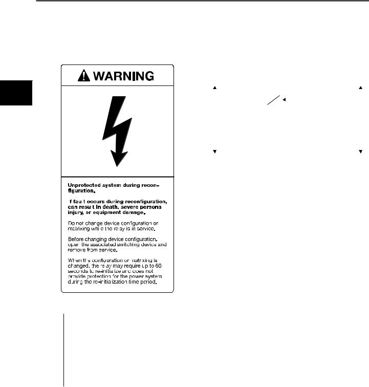
Hardware Configuration
4.2 Device Configuration
The Device Configuration function allows you to set up the ISGS relay to match line frequency, phase sequence, and breaker connection settings of your system.
4
|
|
|
|
|
|
|
|
|
|
|
|
|
|
|
|
|
|
|
|
|
|
|
|
|
|
|
|
|
|
|
|
|
|
|
|
|
|
|
|
|
|
|
|
|
|
|
|
|
|
|
|
|
|
|
|
|
|
|
|
|
|
|
|
|
|
|
|
|
|
|
|
|
|
|
|
|
|
|
|
|
|
|
|
|
|
|
|
|
|
|
|
|
|
|
|
|
|
|
|
|
|
|
|
|
|
|
|
|
|
|
|
|
|
|
|
|
|
|
|
|
|
|
|
|
|
|
|
|
|
|
|
|
|
|
|
|
|
|
|
|
|
|
|
1000 |
Device Configuration |
|
|
||||||||
Address |
Parameter |
Options |
|||||||||
1002 |
Frequency |
50Hz or 60Hz |
|||||||||
1003 |
Phase Sequence |
123 (ABC) or 132 (ACB) |
|||||||||
1004 |
Breaker |
Trip 1, Trip 2, Trip 3, Trip 1 & 2, |
|||||||||
|
Connection |
Trip 1 |
& 3, Trip 2 & 3, or |
||||||||
|
|
|
|
|
|
|
|
Trip 1 |
& 2 & 3 |
|
|
1005 |
Trip Time |
0.01-32.00 s (0.01 s steps) |
|||||||||
|
|
|
|
|
|
|
|
|
|
|
|
The frequency parameter (1002) must be set to the nominal frequency of your system. Phase sequence (1003) selects the phase sequence of your system as it enters the ISGS relay. The breaker connection parameter (1004) selects the trip contact that your breaker is connected to. Many functions use this parameter to determine if the device is attempting to open the breaker. Breaker failure can be initiated by either one of the three trips (if the Breaker Failure function is enabled). The default is set to Trip 1.
4.3 Setting Binary Input Voltages
Binary inputs are jumpered to correspond to the auxiliary supply voltage of the relay in which they are installed. The inputs will correctly respond to DC or AC depending on the jumpering. The jumpers can be placed to allow the inputs to work with any of the available voltages, independent of the auxiliary supply voltage. Refer to Figure 4.5 and Table 4.1.
|
|
|
|
|
|
|
|
|
|
|
|
|
|
|
|
|
|
|
|
|
|
|
|
|
|
|
|
|
|
|
|
|
|
|
|
|
|
13 |
|
|
|
|
|
|
|
|
120 VAC |
SourceVAC120 |
|
Monitoredbeto |
|||
|
|
||||||||||||||||
BusVDC125 |
ISGS |
21 |
|
|
|
|
|
|
|
Aux Relay |
|
||||||
|
|
|
|
|
|
|
|
||||||||||
|
|
|
|
|
|
|
|
|
|
|
|
|
|||||
|
|
|
|
|
|
|
|
|
|
|
|
|
|
|
|||
|
|
|
|
|
|
|
|
|
|
|
|
|
|
|
|||
|
|
BI 1 |
|
|
|
|
|
||||||||||
|
|
|
|
|
|
|
|
||||||||||
|
|
Relay |
22 |
|
|
|
|
||||||||||
|
|
|
|
|
|
|
|
|
|
|
|
|
|
|
|||
|
|
|
|
|
|
|
|
|
|
|
|
|
|
|
|||
|
12 |
|
|
|
|
|
|
|
|
|
|
|
|
|
|
||
|
|
|
|
|
|
|
|
|
|
|
|
|
|
|
|
|
|
|
|
|
|
|
|
|
|
|
|
|
|
|
|
|
|
|
|
|
|
|
|
|
|
|
|
|
|
|
|
|
|
|
|
|
|
|
|
|
|
|
|
|
|
|
|
|
|
|
|
|
|
|
|
Figure 4.4 Binary Inputs Independent of Supply Voltage
Table 4.1 lists the possible jumper positions for setting binary input voltages. The numbers in this table each refer to a pin from and to which a jumper can be moved.
Table 4.1 Jumper Positions
Voltage |
BI 1 |
BI 2 |
BI 3 |
BI 4 |
|
Supply |
Terminals |
Terminals |
Terminals |
Terminals |
|
|
21/22 |
23/22 |
25/26 |
27/28 |
|
|
|
|
|
|
|
48 V |
X111-X112 |
X23-X22 |
X34-X35 |
X46-X47 |
|
|
|
|
|
|
|
|
X13-X14 |
X25-X26 |
X37-X38 |
X49-X50 |
|
|
|
|
|
|
|
|
X16-X17 |
X28-X29 |
X40-X41 |
X52-X53 |
|
|
|
|
|
|
|
|
X19-X20 |
X31-X32 |
X43-X44 |
X55-X56 |
|
|
|
|
|
|
|
125 V |
X111-X112 |
X23-X22 |
X34-X35 |
X46-X47 |
|
(Default) |
|
|
|
|
|
X13-X14 |
X25-X26 |
X37-X38 |
X49-X50 |
||
|
|||||
|
|
|
|
|
|
|
X17-X18 |
X29-X30 |
X41-X42 |
X53-X54 |
|
|
|
|
|
|
|
|
X19-X20 |
X31-X32 |
X43-X44 |
X55-X56 |
|
|
|
|
|
|
|
120 VAC |
X110-X111 |
X24-X23 |
X35-X36 |
X47-X48 |
|
|
|
|
|
|
|
|
X14-X15 |
X26-X27 |
X38-X39 |
X50-X51 |
|
|
|
|
|
|
|
|
X17-X18 |
X29-X30 |
X41-X42 |
X53-X54 |
|
|
|
|
|
|
|
|
X20-X21 |
X32-X33 |
X44-X45 |
X56-X57 |
|
|
|
|
|
|
|
250 VDC |
X111-X112 |
X23-X22 |
X34-X35 |
X46-X47 |
|
|
|
|
|
|
|
|
X14-X15 |
X26-X27 |
X38-X39 |
X50-X51 |
|
|
|
|
|
|
|
|
X17-X18 |
X29-X30 |
X41-X42 |
X53-X54 |
|
|
|
|
|
|
|
|
X19-X20 |
X31-X32 |
X43-X44 |
X55-X56 |
|
|
|
|
|
|
h
16 |
Siemens Energy & Automation, Inc. |
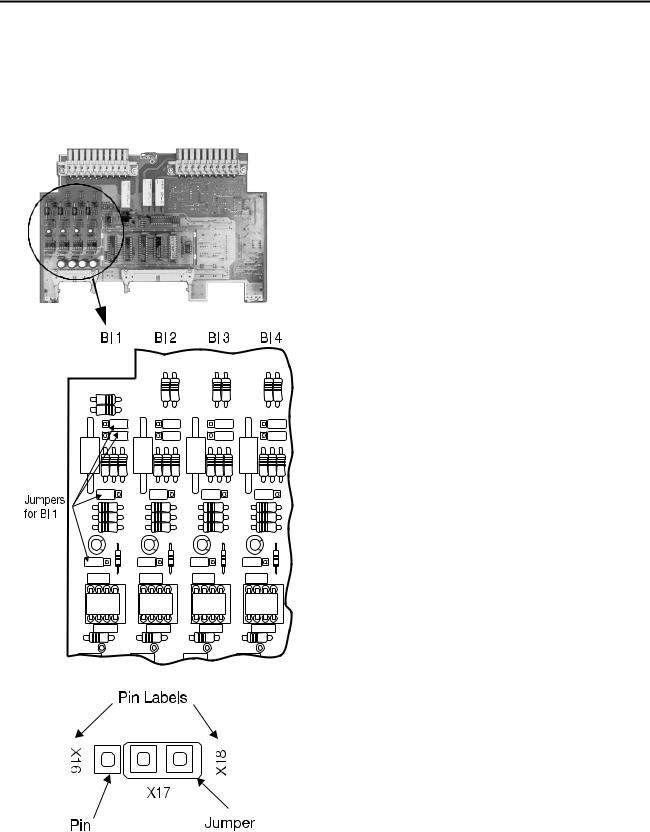
Hardware Configuration
Figure 4.5 shows option board 2 and its jumpers. The drawing indicates the jumpers associated with each binary input. The enlarged set of pins shows an example of pin labeling and a jumper at location X17-X18.
350 |
350 |
350 |
350 |
.22 163 |
.22 163 |
.22 163 |
.22 163 |
Figure 4.5 Option Board 2 with Binary Inputs
Changing Jumper Positions
IMPORTANT:
The relay module contains CAMS circuits. Electrostatic discharges into or around the relay cradle or any of its components must be avoided. Use grounding straps or touch a grounded metal surface before handling the relay cradle.
1. Remove the cradle assembly from the case as |
4 |
|
described in Section 2.6.1. |
||
|
||
|
|
2.Set the relay on its back.
3.With a small screwdriver, remove the four screws (on the sides of the relay) that hold the front panel to the relay cradle.
4.Lift the front panel and hang it in the slots provided on the left side of the casing. Take care not to damage the ribbon cables that connect the electronics in the cradle to the front panel electronics.
5.Disconnect the two ribbon cables from the main board and the option board 2. The main board is the center board which is screwed to the option board 2 on its right.
6.Withdraw these two attached boards and set them on the workplace with the jumper side up (see Figure 4.5).
7.Each jumper is pushed over two out of three pins. Each pin is labeled with numbers identical to those in Table 4.1. The numbers of two side-by-side pins represent a possible jumper position.
8.With a small needle nose pliers, lift the desired jumper off of its pins and push it down over another two pins of the same set.
Example: In Figure 4.5, the jumper is over pins X17 and X18, a default setting for a 125 V power supply. For a 48 V power supply, set this jumper to X16-X17.
Repeat this step until all desired jumpers are repositioned.
9.Insert the attached boards back into the cradle. The connectors of each board must snap into the terminals of the casing.
10.Reattach the two ribbon cables to the main board and the option board 2.
11.Unhook the front panel and carefully place it over the cradle. Lift the front panel slightly to make sure that the ribbon cables connected to the front panel are positioned in their assigned space to prevent damage.
12.Insert and tighten the four front panel screws.
13.Insert the cradle into the casing as described in
Section 2.6.2.
Siemens Energy & Automation, Inc. |
17 |

Hardware Configuration |
|
|
|
4.4 |
CT Configuration |
Main Bus |
|
The CT Configuration function allows you to set up the ISGS |
|||
relay to match the phase CT primary rating, the neutral or |
|
|
|
ground CT primary rating, and the CT input’s normal power |
|
|
|
flow setting of your system. For CT connections refer to |
ISGS |
|
|
Figure 4.8. |
|
||
|
|
||
4 |
|
|
ISGS |
|
Power |
Power |
|
|
|
||
|
|
Normal Power Flow |
Reverse Power Flow |
|
|
(Into CT Polarity Mark) |
(Out of CT Polarity Mark) |
|
|
Figure 4.6 Normal/Reverse Power Flow |
|
4.5 VT Configuration
Use this address block to configure the ISGS relay to match the VT primary rating and the VT connection setting for your system. These settings are available only if the voltage input option is installed on the relay.
|
|
|
|
|
|
|
|
|
|
|
|
|
|
|
|
|
|
|
|
|
|
|
|
|
|
|
|
|
|
|
|
|
|
|
|
|
|
|
|
|
|
|
|
|
|
|
|
|
|
|
|
|
|
|
|
|
|
|
|
|
|
|
|
|
|
|
|
|
|
|
|
|
|
|
|
|
|
|
|
|
|
|
|
|
|
|
|
|
|
|
|
|
|
|
|
|
|
|
|
|
|
|
|
|
|
|
|
|
|
|
|
|
|
|
|
|
|
|
|
|
|
|
|
|
|
|
|
|
|
|
|
|
|
|
|
|
|
|
|
|
|
|
|
|
|
|
|
|
|
|
|
|
|
|
|
|
|
|
|
|
|
|
|
|
|
|
|
|
|
|
|
|
|
|
|
|
|
|
|
|
|
|
|
|
|
|
|
|
|
|
|
|
|
|
|
|
|
|
|
|
|
|
|
|
|
|
|
|
|
|
|
|
|
|
|
|
|
|
|
|
|
|
|
|
|
|
|
|
|
|
|
|
|
|
|
|
|
|
|
|
|
|
|
|
|
|
|
|
|
|
|
1100 |
CT Configuration |
|
|
|
|
|
|
|
|
|
|
||||||
Address |
Parameter |
Options |
|
|
|
|
|
|
|
||||||||
|
|
|
|
|
|
|
|||||||||||
1101 |
Phase CT Primary |
5-8000 A (1 A steps) |
|
|
|
|
|
|
|
||||||||
|
Rating |
|
|
|
|
|
|
|
|
|
|
||||||
1102 |
Neutral or Ground |
5-8000 A (1 A steps) |
|
|
|
|
|
|
|
||||||||
|
|
|
|
|
|
|
|||||||||||
|
CT Primary Rating |
|
|
|
|
|
|
|
|
|
|
||||||
|
|
|
|
|
|
|
|
|
|
|
|||||||
1104 |
Power Flow |
Normal or Reverse |
|
|
|
|
|
|
|
||||||||
|
|
|
|
|
|
|
|
|
|
|
|
|
|
|
|
|
|
The phase (1101) and neutral/ground (1102) CT primary ratings are independently configurable. However, when a residual sensing method is used for ground fault protection, the primary current ratings for the neutral CT and the phase CT must be equal. The CT secondary ratings (1A or 5A) are set at the factory and are not changeable from the front panel.
Power flow is also referred to as top feed or bottom feed. If the power enters the polarity mark on the CTs, set the Power Flow parameter (1104) to Normal. If power leaves the polarity mark, enter Reverse. Figure 4.6 illustrates examples of normal and reverse power flow.
18 |
Siemens Energy & Automation, Inc. |
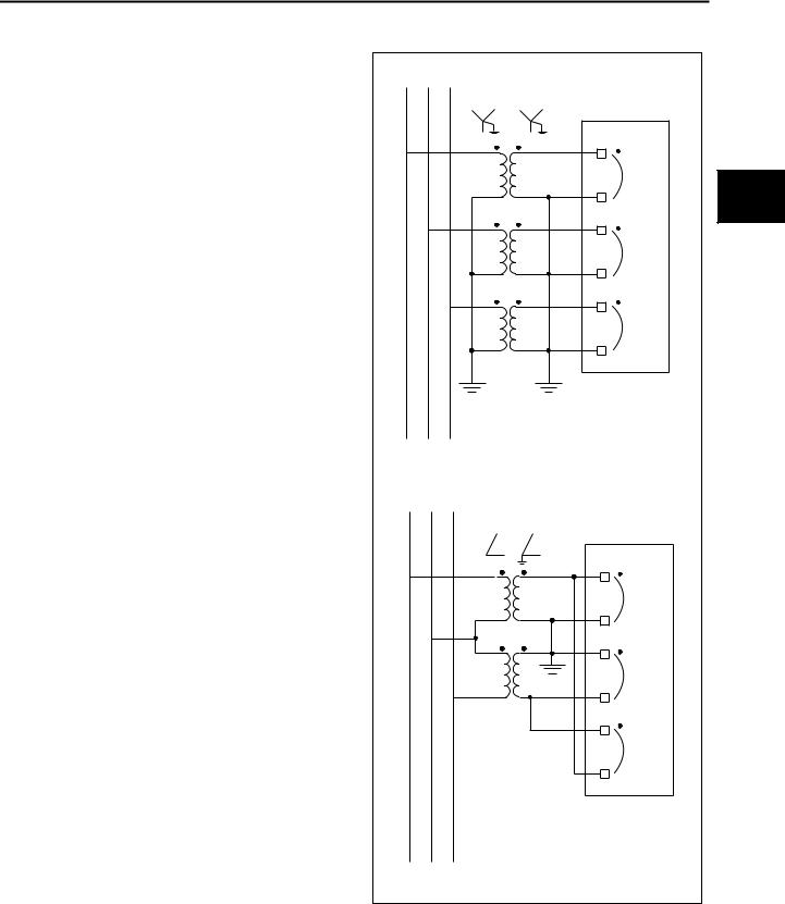
Hardware Configuration
1200 |
VT Configuration |
|
Address |
Parameter |
Options |
1201 |
Primary Rating |
120-138,000 V (1 V steps) |
1202 |
VT Connect |
Line-to-Line or Line-to-Neutral |
1203 |
Sec. VT Rating |
100-120 V (1 V steps) |
|
|
|
Voltage transformers may be connected in either of two ways:
•Two VTs connected open delta-open delta
•Three VTs connected wye-wye
For brevity, the open delta connection is referred to as L-L (line-to-line), while the wye connection is referred to as L-N (line-to-neutral). Wye-delta or delta-wye connection of VTs is not allowed. Figure 4.7 shows the correct VT connections and polarities.
Voltage transformers are specified with an input to output voltage ratio (for example, 12000:120). The secondary voltage rating of the VTs can be set by the Secondary Voltage Rating parameter (1203).
Before leaving the hardware configuration blocks, (only when changing parameters, not when viewing) the ISGS relay displays the message “END OF PASSWORD OPERATION?”. Press the No button to return to one of the configuration blocks. The message “PRESS ANY KEY TO CONTINUE” appears. Press any key to return to the screen displayed last before the message prompt appeared. Press the Yes button if you are finished with the configuration changes. The device prompts you to save the settings.
•Press the Yes button to save the settings. The relay resets and displays the Power On and Power Meter On displays.
•Press the No button if you do not want to save the changes The message “SAVING PROCEDURE ABORTED” appears. Press Enter to return to the last address block.
Note: For CT configuration, CTs on the neutral must be the same rating as other CTs for residual ground sensing, directional neutral sensing, or direct ground sensing.
For VT connections, VTs must be either wye-wye or delta-delta. Wye-delta or delta-wye connections are not permissible.
1 |
2 |
3 |
|
|
|
ISGS |
|
|
|
41 |
|
|
|
V1 |
|
|
|
42 |
4 |
|
|
43 |
|
|
|
V2 |
|
|
|
44 |
|
|
|
45 |
|
|
|
V3 |
|
|
|
46 |
|
|
|
Wye-Wye VT Connection |
|
1 |
2 |
3 |
|
|
|
ISGS |
|
|
|
41 |
|
|
|
V12 |
|
|
|
42 |
|
|
|
43 |
|
|
|
V23 |
|
|
|
44 |
|
|
|
45 |
|
|
|
V31 |
|
|
|
46 |
|
|
Open Delta-Open Delta VT Connection |
|
|
Figure 4.7 Voltage Transformer Connections
Siemens Energy & Automation, Inc. |
19 |
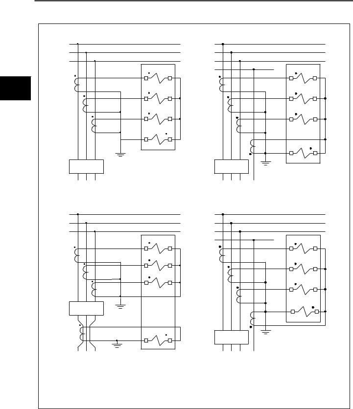
Hardware Configuration
|
1 |
|
1 |
|
|
2 |
|
2 |
|
|
3 |
ISGS |
3 |
ISGS |
|
|
N |
||
|
|
1 |
1 |
|
|
|
|
||
4 |
3 |
4 |
3 |
4 |
|
2 |
|
2 |
|
|
5 |
6 |
5 |
6 |
|
|
3 |
|
3 |
|
7 |
8 |
7 |
8 |
|
|
N |
|
|
|
10 |
9 |
|
N |
|
|
|
|
|
|
|
|
10 |
9 |
|
52 |
|
52 |
|
Three Phase Current with Residual Ground Sensing |
Three Phase Current with Direct Neutral Sensing |
1 |
|
1 |
|
2 |
|
2 |
|
3 |
|
3 |
|
ISGS |
G |
ISGS |
|
1 |
|
1 |
|
|
|
||
3 |
4 |
3 |
4 |
2 |
|
|
2 |
|
|
|
|
5 |
6 |
5 |
6 |
3 |
|
||
|
|
|
|
7 |
8 |
|
3 |
|
|
||
|
|
7 |
8 |
52 |
|
|
N |
|
|
10 |
9 |
N |
|
52 |
|
10 |
9 |
|
|
Three Phase Current with Zero Sequence CT |
Three Phase Current with Direct Ground Sensing |
||
52 = Power Circuit Breaker

 = ISGS Internal CT
Figure 4.8 Current Transformer Configuration
20 |
Siemens Energy & Automation, Inc. |

Protective Function Configuration
5 Protective Function Configuration
5.1 Overview
This chapter explains how to set the parameters for the protective functions of the ISGS relay.
Password
All parameter changes require a password. Refer to Section 3.3 on how to enter your password. Viewing parameter settings does not require a password.
Note: The ISGS relay is not password protected when making parameter changes through Wisdom software.
Configuration Steps
Perform parameter changes using steps 1 through 9 of the standard operating procedures described in Section 3.5.
Parameter Sets
Many protective functions can be set to two different parameter sets—set A and set B. These functions are indicated by the letter A or B preceding the address block number. Alternate sets are useful for seasonal settings or for special operating periods. Either set can be selected (in address block 7100) to be the active set that controls the relay operation. The parameters for both sets are entered in the relevant address blocks. Waveform capture buffer settings apply to both parameter sets. Unless you do not desire an alternate set, configure both sets when configuring the relay.
Note: The settings for parameter sets A and B are entered in the address block. However, the parameter set which the ISGS relay is actively using is selected at address block 7100. Refer to Section 6.11 for discussion of parameter sets.
Actions on Pickup or Trip
Protective functions can be set to have actions occur on pickup or on trip. Binary outputs can be set to be actuated on pickup of a protective function. A protective function is set to trip a breaker by assigning the trip contact that is connected to the breaker (default is Trip 1). Binary outputs can also be assigned to trip a breaker. It is possible, however to have a protective function enabled and not assigned to any output. Events and their sequences are entered in the trip log as usual, but the breaker will not be affected. This setting is useful for monitoring and alarming without tripping, and for waveform capture. For more information on the control of inputs and outputs, refer to Chapter 6.
Pickup
When testing induction disk relays, an established practice is to set the pickup value to 1.0 A of secondary CT output. The time overcurrent curves will show a pickup, but the relay will not trip in a predefined repeatable manner until it reaches 1.3 to 1.5 A. With numerical relays like the ISGS, however, a sustained pickup indication means definite operation. To account for measurement inaccuracies, and to guarantee that the relay will never trip at 100% of pickup or below, the pickup point is set at 106% of the pickup setting to avoid any unintended nuisance trips.
Neutral or Ground
The availability of protective functions for neutral or ground depends on how the external CTs are connected. If a ground or zero-sequence CT is used and connected to the fourth internal CT, the ground or neutral protective function is a ground function. If the fourth CT is connected in the common return of the other three internal CTs (residual), the function is indicated as being neutral. There does not need to be an explicit selection of neutral or ground.
Custom Curve
The custom curve is one user-defined curve that can be used by one or more protective functions that have the custom curve option in the curve list.
Wisdom Software
5
While the ISGS relay protective functions can be completely configured manually using the LCD and the keypad, Wisdom software allows faster and easier configuration when it is used on a PC connected to either data port. For data port connections refer to Section 2.5.
5.2 Instantaneous Phase Overcurrent (50)
The Instantaneous Phase Overcurrent function consists of a phase instantaneous overcurrent function and an adjustable delay. This function begins timing when any individual phase current exceeds the pickup at 100% of set pickup point and drops out at 95% of the pickup point.
A1500 |
Instantaneous Phase Overcurrent (50) |
|
Address |
Parameter |
Option |
1501 |
Function |
Enabled or Disabled |
1502 |
Pickup |
5 A CTs: 1-120 A |
|
|
1 A CTs: 0.2-24 A |
|
|
(0.1 A steps) |
1504 |
Time Delay |
0-60 s (0.01 s steps) |
1510 |
Freeze Wfm1 |
on Pickup, on Trip, or None |
1511 |
Freeze Wfm2 |
on Pickup, on Trip, or None |
1512 |
Blocked by |
None, 50HS & 50HSN, 50 HSN, |
|
|
or 50HS |
|
|
|
The function can be enabled or disabled (1501).
The range of the pickup value (1502) depends on the secondary phase CT rating (1 A or 5 A), and the value is in secondary amperes.
The time delay (1504) represents the time between pickup and trip and can be adjusted from 0 to 60 seconds in steps of 0.1 second. If the function remains in pickup for longer than the time delay, the function causes a trip. The delay can also be set to infinity so that the function never times out.
Each of the two waveform capture buffers (1510 and 1511) can be independently programmed to freeze snapshots on pickup or trip.
The function is able to actuate any binary output contact on pickup, and any trip or binary output contact on trip.
Siemens Energy & Automation, Inc. |
21 |

Protective Function Configuration
5.3High-Set Instantaneous Phase Overcurrent (50HS)
The High-Set Instantaneous Phase Overcurrent function causes an undelayed trip when any individual measured phase current exceeds the preprogrammed threshold (pickup value). The relay will trip at 100% of the set pickup point.
|
|
A1500 |
High-SetInstantaneous Phase Overcurrent (50HS) |
||
|
|
Address |
Parameter |
Option |
|
|
|
1551 |
Function |
Enabled or Disabled |
|
|
|
||||
5 |
|
1552 |
Pickup |
5A |
CTs: 5-120 A or |
|
|
|
1A |
CTs: 0.2-24 A |
|
|
|
|
|
(0.1 A steps) |
|
|
|
|
|
||
|
|
1560 |
Freeze Wfm1 |
on Trip, or None |
|
|
|
1561 |
Freeze Wfm2 |
on Trip, or None |
|
|
|
|
|
|
|
The Instantaneous Neutral or Ground Overcurrent function can be enabled or disabled (1601). The form of protection provided depends on the manner in which the external CTs are connected to the ISGS relay. Figure 4.5 in Chapter 4 shows correct CT connections and polarities.
The range of the pickup value (1602) depends on the secondary neutral CT rating (1 A or 5 A) and the value is in secondary amperes.
The time delay (1604) represents the time between pickup and trip and can be adjusted from 0 to 60 seconds in steps of 0.1 second. If the function remains in pickup for longer than the time delay, this parameter causes a trip. The delay can also be set to infinity so that the function never times out.
Each of the two waveform capture buffers (1610 and 1611) can be independently programmed to freeze snapshots on pickup or trip.
The function can be enabled or disabled (1551). The range of the pickup value (1552) depends on the secondary phase CT rating (1 A or 5 A) and the value is in secondary amperes.
Each of the two waveform capture buffers (1560 and 1561) can be independently programmed to freeze snapshots on trip.
The function is able to actuate any binary output contact on pickup, and any trip or binary output contact on trip.
5.4Instantaneous Neutral or Ground Overcurrent (50N)
The Instantaneous Neutral or Ground Overcurrent function has an adjustable delay whose input is the current measured by the neutral CT. It begins timing when the neutral or ground current exceeds the pickup value. The ISGS relay will pickup at 100% of set pickup point and drop out at 95% of the pickup point.
A1600 |
Instantaneous Neutral or Ground Overcurrent |
|
|
(50N) |
|
Address |
Parameter |
Option |
1601 |
Function |
Enabled or Disabled |
1602 |
Pickup |
5 A CTs: 1-120 A or |
|
|
1 A CTs: 0.2-24 A |
|
|
(0.1 A steps) |
1604 |
Time Delay |
0-60 s (0.01 s steps) |
1610 |
Freeze Wfm1 |
on Pickup, on Trip, or None |
|
|
|
1611 |
Freeze Wfm2 |
on Pickup, on Trip, or None |
1612 |
Blocked by |
None, 50HS & 50HSN, 50HSN, |
|
|
or 50HS |
|
|
|
The function is able to actuate any binary output contact on pickup, and any trip or binary output contact on trip.
5.5High-Set Instantaneous Neutral or Ground Overcurrent (50HSN)
The High-Set Instantaneous Neutral or Ground Overcurrent function causes an undelayed trip when any individual measured phase current exceeds the preprogrammed threshold (pickup value). The relay will trip at 100% of the set pickup point.
A1600 |
High-Set Instantaneous Neutral or Ground |
|
|
Overcurrent (50HSN) |
|
Address |
Parameter |
Option |
1651 |
Function |
Enabled or Disabled |
1652 |
Pickup |
5 A CTs: 5-120 A or |
|
|
1 A CTs: 0.2-24 A |
|
|
(0.1 A steps) |
1660 |
Freeze Wfm1 |
on Trip, or None |
1661 |
Freeze Wfm2 |
on Trip, or None |
|
|
|
The High-Set Instantaneous Neutral or Ground Overcurrent function can be enabled or disabled (1651).
The range of the pickup value (1652) depends on the secondary phase CT rating (1 A or 5 A) and the value is in secondary amperes.
Each of the two waveform capture buffers (1660 and 1661) can be independently programmed to freeze snapshots on trip.
The function is able to actuate any binary output contact on pickup, and any trip or binary output contact on trip.
22 |
Siemens Energy & Automation, Inc. |

Protective Function Configuration
5.6 Phase Time Overcurrent (51)
The Phase Time Overcurrent function uses a selected time overcurrent characteristic curve to determine the trip time for the applied phase currents. The defined characteristic curves are valid over a range of multiple of pickup values. The function also includes the ability to select a customer defined curve. This function is always enabled. Refer to Appendix A for detailed trip curve information.
A1700 |
Phase Time Overvurrent (51) |
|
Address |
Parameter |
Option |
1702 |
Curve |
Inverse |
|
|
Short Inverse |
|
|
Long Inverse |
|
|
Moderately Inverse |
|
|
Custom |
|
|
Very Inverse |
|
|
Extremely Inverse |
|
|
Definite Inverse |
|
|
Slightly Inverse |
|
|
I2T Without Limit |
1703 |
Pickup |
5 A CTs: 0.5-20 A or |
|
|
1 A CTs: 0.1-4 A |
|
|
(0.1 A steps) |
1705 |
Time Dial |
0.1-9.9 (0.1 steps) |
1706 |
Filter |
rms or fundamental |
1709 |
Reset |
Instantaneous or Disk Emulation |
1710 |
Freeze Wfm1 |
on Pickup, on Trip, or None |
1711 |
Freeze Wfm2 |
on Pickup, on Trip, or None |
1712 |
Blocked by |
None, 50HS, 50HSN, or |
|
|
50HS & 50 HSN |
|
|
|
The Curve parameter (1702) allows the selection of the preprogrammed characteristic curve used by this function. The ISGS relay comes with nine standard and one custom overcurrent characteristic curves that can be adjusted with the Time Dial parameter. The custom curve is a user-definable protective curve that integrates with instantaneous reset. The lower limit of the custom curve is 1.10. The maximum time to trip is the time at 1.10.
The range of the pickup value (1703) depends on the secondary phase CT rating (1 A or 5 A) and the value is in secondary amperes. The function begins timing when any individual phase current exceeds the pickup current setting.
Note: The pickup point is 1.06 of the pickup setting. Refer also to paragraph on Pickup in
Section 5.1.
The Time Dial parameter (1705) used for the selected curve allows the time-to-trip of the curve to be raised or lowered The dial can be adjusted from 0.1 to 9.9 in steps of 0.1.
The Filter parameter (1706) sets the sensing method used by the function in its pickup calculations. The rms filter uses fundamental current plus harmonics, while the fundamental filter ignores harmonics.
The Reset parameter (1709) offers instantaneous or disk |
|
|
emulation settings. Selecting Instantaneous causes the relay |
|
|
to clear the timer when the current drops below the pickup |
|
|
threshold. Selecting Disk Emulation causes the relay to simu- |
|
|
late the integrating disk characteristics of electromechanical |
|
|
relays, where the delay time decays over time. With disk |
|
|
emulation, a relay that continuously picks up and drops out |
|
|
will eventually trip. Set this parameter to Instantaneous when |
|
|
using a custom curve. |
|
|
Each of the two waveform capture buffers (1710 and 1711) |
|
|
can be independently programmed to freeze snapshots on |
|
|
pickup or trip. |
|
|
The function is able to actuate any binary output contact on |
5 |
|
pickup, and any trip or binary output contact on trip. |
||
|
5.7 Neutral Time Overcurrent (51N)
The Neutral Time Overcurrent function uses a selected time overcurrent characteristic curve to determine the trip time for the applied current at the fourth current input. The defined characteristic curves are valid over a range of multiple of pickup values. The function also includes a customer defined curve. Refer to Appendix A for detailed trip curve information.
A1800 |
Neutral Time Overcurrent (51N) |
|
Address |
Parameter |
Option |
1801 |
Function |
Enabled or Disabled |
1802 |
Curve |
Inverse |
|
|
Short Inverse |
|
|
Long Inverse |
|
|
Moderately Inverse |
|
|
Custom |
|
|
Very Inverse |
|
|
Extremely Inverse |
|
|
Definite Inverse |
|
|
Slightly Inverse |
|
|
I2T Without Limit |
1803 |
Pickup |
5 A CTs: 0.5-20 A or |
|
|
1 A CTs: 0.1-4 A |
|
|
(0.1 A steps) |
1805 |
Time Dial |
0.1-9.9 (0.1 steps) |
1806 |
Filter |
rms or fundamental |
1809 |
Reset |
Instantaneous or Disk Emulation |
1810 |
Freeze Wfm1 |
on Pickup, on Trip, or None |
1811 |
Freeze Wfm2 |
on Pickup, on Trip, or None |
1812 |
Blocked by |
None, 50HS, 50HSN, or |
|
|
50HS & 50 HSN |
|
|
|
The Neutral or Ground Time Overcurrent function can be enabled and disabled (1801).
The Curve parameter (1702) allows the selection of the preprogrammed characteristic curve used by this function. The ISGS relay comes with nine standard and one custom overcurrent characteristic curves that can be adjusted with the Time Dial parameter. The custom curve is a user-definable
Siemens Energy & Automation, Inc. |
23 |
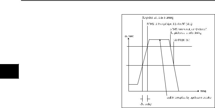
Protective Function Configuration
protective curve that integrates with instantaneous reset. The lower limit of the custom curve is 1.10. The maximum time to trip is the time at 1.10.
The range of the pickup value (1803) depends on the secondary phase CT rating (1 A or 5 A) and the value is in secondary amperes.
The Time Dial parameter (1805) used for the selected curve allows the time-to-trip of the curve to be raised or lowered. The dial can be adjusted from 0.1 to 9.9 in steps of 0.1.
The Filter parameter (1806) sets the sensing method used by the function in its pickup calculations. The rms filter uses fun-
5damental current plus harmonics, while the fundamental filter ignores harmonics.
The Reset parameter (1709) offers instantaneous or disk emulation settings. Selecting Instantaneous causes the relay to clear the timer when the current drops below the pickup threshold. Selecting Disk Emulation causes the relay to simulate the integrating disk characteristics of electromechanical relays, where the delay time decays over time. With disk emulation, a relay that continuously picks up and drops out will eventually trip. Set this parameter to Instantaneous when using a custom curve.
Each of the two waveform capture buffers (1810 and 1811) can be independently programmed to freeze snapshots on pickup or trip.
The function is able to actuate any binary output contact on pickup, and any trip or binary output contact on trip.
5.8Blocking Capability for Breaker or Interrupter Saving
High-set instantaneous phase overcurrent (50HS) and highset instantaneous neutral or ground overcurrent (50HSN) functions have the capability to block 50, 51, 50N, and 51N selectively to prevent opening an interrupting device should the fault current exceed the rating of the device.
This function is used to keep an electrically-operated load break switch, recloser, or aging circuit breaker from attempting to interrupt current beyond its capability or rating. It must be used in conjunction with a slight delay (25 ms) in 50 so that 50HS can pickup or trip before 50 times out and trips. Should these parameters be set, a fault large enough to cause 50HS to pickup or trip before 50 has timed out will prevent 50 and/or 51, 50N, and 51N from tripping.
50HS/N can also be matrixed to an output contact to block differential tripping of a transformer differential relay when a fault is between the interrupter and the high side (bushings) of the transformer.
Figure 5.1 Blocking Capability Diagram
5.9 Directional Phase Time Overcurrent (67)
The Directional Phase Time Overcurrent function uses a selected time overcurrent characteristic curve to determine the trip time for the applied phase currents, utilizing the voltages present on the VTs to determine current direction. The defined characteristic curves are valid over a range of multiple of pickup values. The function also includes a customer defined curve. Refer to Appendix A for detailed trip curve information. This function is only available if the voltage input option is installed.
A1900 |
Directional Phase Time Overcurrent (67) |
|
Address |
Parameter |
Option |
1901 |
Function |
Enabled or Disabled |
1902 |
Curve |
Inverse |
|
|
Short Inverse |
|
|
Long Inverse |
|
|
Moderately Inverse |
|
|
Custom |
|
|
Very Inverse |
|
|
Extremely Inverse |
|
|
Slightly Inverse |
|
|
Definite Inverse |
|
|
I2T Without Limit |
1903 |
Pickup |
5 A CTs: 0.5-20 A or |
|
|
1 A CTs: 0.1-4 A |
|
|
(0.1 A steps) |
1905 |
Time Dial |
0.1-9.9 (0.1 steps) |
1906 |
Filter |
rms or fundamental |
1907 |
Impedance |
0-90° |
1908 |
Direction |
Forward or Reverse |
1910 |
Freeze Wfm 1 |
on Pickup, on Trip, or None |
1911 |
Freeze Wfm 2 |
on Pickup, on Trip, or None |
|
|
|
24 |
Siemens Energy & Automation, Inc. |
 Loading...