


SIMATIC RF300
Siemens SIMATIC RF300, SIMATIC RF310R, SIMATIC RF350T, RF340R, RF350R System Manual
...
SIMATIC Sensors RFID systems SIMATIC RF300
simatic sensors
System Manual Edition 04/2006
RFID-SYSTEMS
SIMATIC RF300


Introduction
1
Safety information
2
System overview
3
RF300 system planning
4
Readers
5
Transponders
6
Communication modules
7
System diagnostics
8
Accessories
9
Appendix
A
SIMATIC Sensors
RFID systems
SIMATIC RF300
System Manual
Release 04/2006
J31069 D0166-U001-A2-7618

Safety Guidelines
This manual contains notices you have to observe in order to ensure your personal safety, as well as to prevent
damage to property. The notices referring to your personal safety are highlighted in the manual by a safety alert
symbol, notices referring only to property damage have no safety alert symbol. These notices shown below are
graded according to the degree of danger.
Danger
indicates that death or severe personal injury will result if proper precautions are not taken.
Warning
indicates that death or severe personal injury may result if proper precautions are not taken.
Caution
with a safety alert symbol, indicates that minor personal injury can result if proper precautions are not taken.
Caution
without a safety alert symbol, indicates that property damage can result if proper precautions are not taken.
Notice
indicates that an unintended result or situation can occur if the corresponding information is not taken into
account.
If more than one degree of danger is present, the warning notice representing the highest degree of danger will
be used. A notice warning of injury to persons with a safety alert symbol may also include a warning relating to
property damage.
Qualified Personnel
The device/system may only be set up and used in conjunction with this documentation. Commissioning and
operation of a device/system may only be performed by qualified personnel. Within the context of the safety notes
in this documentation qualified persons are defined as persons who are authorized to commission, ground and
label devices, systems and circuits in accordance with established safety practices and standards.
Prescribed Usage
Note the following:
Warning
This device may only be used for the applications described in the catalog or the technical description and only in
connection with devices or components from other manufacturers which have been approved or recommended by
Siemens. Correct, reliable operation of the product requires proper transport, storage, positioning and assembly
as well as careful operation and maintenance.
Trademarks
All names identified by ® are registered trademarks of the Siemens AG. The remaining trademarks in this
publication may be trademarks whose use by third parties for their own purposes could violate the rights of the
owner.
Disclaimer of Liability
We have reviewed the contents of this publication to ensure consistency with the hardware and software
described. Since variance cannot be precluded entirely, we cannot guarantee full consistency. However, the
information in this publication is reviewed regularly and any necessary corrections are included in subsequent
editions.
Siemens AG
Automation and Drives
Postfach 48 48
90437 NÜRNBERG
GERMANY
Order No.: J31069 D0166-U001-A2-7618
Edition 05/2006
Copyright © Siemens AG 2006.
Technical data subject to change

SIMATIC RF300
System Manual, Release 04/2006, J31069 D0166-U001-A2-7618
iii
Table of contents
1 Introduction............................................................................................................................................. 1-1
1.1 Navigating in the system manual............................................................................................... 1-1
1.2 Preface....................................................................................................................................... 1-2
2 Safety information................................................................................................................................... 2-1
3 System overview..................................................................................................................................... 3-1
3.1 RFID systems............................................................................................................................. 3-1
3.2 RF300 ........................................................................................................................................ 3-2
3.2.1 RF300 system overview............................................................................................................. 3-2
3.2.2 Application areas of RF300........................................................................................................ 3-3
3.2.3 RFID components and their function ......................................................................................... 3-4
3.2.4 Technical data............................................................................................................................ 3-5
4 RF300 system planning.......................................................................................................................... 4-1
4.1 Fundamentals of application planning .......................................................................................4-1
4.1.1 Selection criteria for SIMATIC RF300 components................................................................... 4-1
4.1.2 Transmission window and read/write distance .......................................................................... 4-2
4.1.3 Width of the transmission window.............................................................................................. 4-5
4.1.4 Impact of secondary fields ......................................................................................................... 4-5
4.1.5 Permissible directions of motion of the transponder.................................................................. 4-6
4.1.6 Operation in static and dynamic mode ...................................................................................... 4-7
4.1.7 Dwell time of the transponder .................................................................................................... 4-8
4.1.8 Communication between communication module, reader (with IQ-Sense interface) and
transponder................................................................................................................................ 4-9
4.1.9 Calculation example (IQ-Sense).............................................................................................. 4-10
4.1.10 Communication between communication module, reader (with RS 422 interface) and
transponder.............................................................................................................................. 4-12
4.1.11 Calculation example (RS 422) ................................................................................................. 4-14
4.2 Field data for transponders, readers and antennas................................................................. 4-16
4.3 Relationship between the volume of data and the transponder speed ................................... 4-19
4.3.1 RF310R with IQ-Sense ............................................................................................................ 4-19
4.3.2 RF310R with RS 422 ............................................................................................................... 4-20
4.3.3 RF340R.................................................................................................................................... 4-23
4.3.4 RF350R.................................................................................................................................... 4-26
4.4 Installation guidelines............................................................................................................... 4-29
4.4.1 Overview .................................................................................................................................. 4-29
4.4.2 Reduction of interference due to metal.................................................................................... 4-29
4.4.3 Effects of metal on different transponders and readers........................................................... 4-32
4.4.4 Impact on the transmission window by metal .......................................................................... 4-33

Table of contents
SIMATIC RF300
iv System Manual, Release 04/2006, J31069 D0166-U001-A2-7618
4.5 Chemical resistance of the transponders................................................................................. 4-38
4.6 EMC Directives ........................................................................................................................ 4-43
4.6.1 Overview .................................................................................................................................. 4-43
4.6.2 What does EMC mean?........................................................................................................... 4-44
4.6.3 Basic rules................................................................................................................................ 4-45
4.6.4 Propagation of electromagnetic interference ........................................................................... 4-47
4.6.5 Cabinet configuration ............................................................................................................... 4-50
4.6.6 Prevention of interference sources .......................................................................................... 4-53
4.6.7 Equipotential bonding............................................................................................................... 4-54
4.6.8 Cable shielding......................................................................................................................... 4-55
5 Readers.................................................................................................................................................. 5-1
5.1 Overview .................................................................................................................................... 5-1
5.2 RF310R with IQ-Sense interface ............................................................................................... 5-2
5.2.1 Features ..................................................................................................................................... 5-2
5.2.2 Display elements of the RF310R reader with IQ-Sense interface ............................................. 5-2
5.2.3 Ensuring reliable data exchange................................................................................................ 5-2
5.2.4 Metal-free area........................................................................................................................... 5-3
5.2.5 Minimum distance between RF310R readers............................................................................ 5-3
5.2.6 Technical data for RF310R reader with IQ-Sense interface...................................................... 5-4
5.2.7 FCC information ......................................................................................................................... 5-5
5.2.8 Ordering data of RF310R with IQ-Sense interface .................................................................... 5-5
5.2.9 Dimension drawing..................................................................................................................... 5-6
5.3 RF310R with RS 422 interface .................................................................................................. 5-7
5.3.1 Features ..................................................................................................................................... 5-7
5.3.2 Display elements of the RF310R reader with RS 422 interface ................................................5-7
5.3.3 Ensuring reliable data exchange................................................................................................ 5-7
5.3.4 Metal-free area........................................................................................................................... 5-8
5.3.5 Minimum distance between RF310R readers............................................................................ 5-8
5.3.6 Technical data of the RF310R reader with RS 422 interface .................................................... 5-9
5.3.7 FCC information ....................................................................................................................... 5-10
5.3.8 Ordering data for RF310R with RS 422 interface .................................................................... 5-10
5.3.9 Dimension drawing................................................................................................................... 5-11
5.4 RF340R.................................................................................................................................... 5-12
5.4.1 Features ................................................................................................................................... 5-12
5.4.2 Display elements of the RF340R reader.................................................................................. 5-12
5.4.3 Ensuring reliable data exchange.............................................................................................. 5-12
5.4.4 Metal-free area......................................................................................................................... 5-13
5.4.5 Minimum distance between RF340R readers.......................................................................... 5-13
5.4.6 Technical data of the RF340R reader...................................................................................... 5-14
5.4.7 FCC information ....................................................................................................................... 5-15
5.4.8 Ordering data for RF340R........................................................................................................ 5-15
5.4.9 Dimension drawing................................................................................................................... 5-16

Table of contents
SIMATIC RF300
System Manual, Release 04/2006, J31069 D0166-U001-A2-7618
v
5.5 RF350R.................................................................................................................................... 5-17
5.5.1 Features................................................................................................................................... 5-17
5.5.2 Display elements of the RF350R reader.................................................................................. 5-17
5.5.3 Ensuring reliable data exchange.............................................................................................. 5-17
5.5.4 Metal-free area......................................................................................................................... 5-18
5.5.5 Technical data of the RF350R reader...................................................................................... 5-18
5.5.6 FCC information....................................................................................................................... 5-19
5.5.7 Ordering data for RF350R ....................................................................................................... 5-19
5.5.8 Dimension drawing .................................................................................................................. 5-20
5.5.9 Antennas.................................................................................................................................. 5-21
5.5.9.1 Features................................................................................................................................... 5-21
5.5.9.2 Ensuring reliable data exchange.............................................................................................. 5-23
5.5.9.3 Metal-free area......................................................................................................................... 5-23
5.5.9.4 Minimum distance between antennas ..................................................................................... 5-25
5.5.9.5 Technical data for antennas..................................................................................................... 5-27
5.5.9.6 Ordering data for antennas...................................................................................................... 5-27
5.5.9.7 Dimension drawings for antennas............................................................................................ 5-28
6 Transponders ......................................................................................................................................... 6-1
6.1 Overview .................................................................................................................................... 6-1
6.2 RF320T ...................................................................................................................................... 6-1
6.2.1 Features..................................................................................................................................... 6-1
6.2.2 Metal-free area........................................................................................................................... 6-2
6.2.3 Technical data............................................................................................................................ 6-3
6.2.4 Ordering data ............................................................................................................................. 6-3
6.2.5 Dimension drawing .................................................................................................................... 6-4
6.3 RF340T ...................................................................................................................................... 6-5
6.3.1 Features.................................................
.................................................................................... 6-5
6.3.2 Metal-free area........................................................................................................................... 6-6
6.3.3 Technical data............................................................................................................................ 6-7
6.3.4 Ordering data ............................................................................................................................. 6-7
6.3.5 Dimension drawing .................................................................................................................... 6-8
6.4 RF350T ...................................................................................................................................... 6-9
6.4.1 Features..................................................................................................................................... 6-9
6.4.2 Metal-free area......................................................................................................................... 6-10
6.4.3 Technical data.......................................................................................................................... 6-11
6.4.4 Ordering data ........................................................................................................................... 6-11
6.4.5 Dimension drawing .................................................................................................................. 6-12
6.5 RF360T .................................................................................................................................... 6-13
6.5.1 Features................................................................................................................................... 6-13
6.5.2 Metal-free area......................................................................................................................... 6-14
6.5.3 Technical data.......................................................................................................................... 6-16
6.5.4 Ordering data ........................................................................................................................... 6-16
6.5.5 Dimension drawing .................................................................................................................. 6-17
6.6 Memory configuration of the RF300 tags................................................................................. 6-18

Table of contents
SIMATIC RF300
vi System Manual, Release 04/2006, J31069 D0166-U001-A2-7618
7 Communication modules ......................................................................................................... 7-1
7.1 8xIQ-Sense ................................................................................................................................ 7-1
7.1.1 Features ..................................................................................................................................... 7-1
7.1.2 Indicators.................................................................................................................................... 7-2
7.1.3 Configuration.............................................................................................................................. 7-3
7.1.4 Addressing ................................................................................................................................. 7-5
7.1.5 Technical data............................................................................................................................ 7-7
7.1.6 Ordering data ............................................................................................................................. 7-7
7.2 ASM 452..................................................................................................................................... 7-8
7.2.1 Features ..................................................................................................................................... 7-8
7.2.2 Pin assignment and display elements........................................................................................ 7-9
7.2.3 Configuration............................................................................................................................ 7-10
7.2.4 Technical data.......................................................................................................................... 7-14
7.2.5 PROFIBUS Diagnosis.............................................................................................................. 7-15
7.2.6 Dimensional drawings.............................................................................................................. 7-16
7.2.7 Ordering data ........................................................................................................................... 7-17
7.3 ASM 456................................................................................................................................... 7-18
7.3.1 Description ............................................................................................................................... 7-18
7.3.2 Setting the PROFIBUS address............................................................................................... 7-22
7.3.3 Wiring up ASM 456 .................................................................................................................. 7-25
7.3.4 Diagnosis using LEDs .............................................................................................................. 7-30
7.3.5 Technical data.......................................................................................................................... 7-32
7.3.6 Dimensional drawings.............................................................................................................. 7-33
7.3.7 Ordering data ........................................................................................................................... 7-34
7.4 ASM 473................................................................................................................................... 7-35
7.4.1 Features ................................................................................................................................... 7-35
7.4.2 Pin assignment and display elements.....................................................................................
. 7-36
7.4.3 Configuration............................................................................................................................ 7-37
7.4.4 Technical data.......................................................................................................................... 7-40
7.4.5 Dimensional drawings.............................................................................................................. 7-41
7.4.6 Ordering data ........................................................................................................................... 7-42
7.5 ASM 475................................................................................................................................... 7-43
7.5.1 Features ................................................................................................................................... 7-43
7.5.2 Indicators.................................................................................................................................. 7-44
7.5.3 Configuration............................................................................................................................ 7-46
7.5.4 Technical data.......................................................................................................................... 7-49
7.5.5 Ordering data ........................................................................................................................... 7-50
8 System diagnostics................................................................................................................................. 8-1
8.1 Overview .................................................................................................................................... 8-1
8.2 Reader diagnostics with SLG STATUS ..................................................................................... 8-2
8.3 Transponder diagnostics with MDS STATUS............................................................................ 8-4
9 Accessories ............................................................................................................................................ 9-1
9.1 RFID Systems Software & Documentation ................................................................................ 9-1

Table of contents
SIMATIC RF300
System Manual, Release 04/2006, J31069 D0166-U001-A2-7618
vii
A Appendix .................................................................................................................................A-1
A.1 Certificates and Approvals......................................................................................................... A-1
A.2 Service and support ................................................................................................................... A-4
A.3 Contacts.....................................................................................................................................A-4
A.4 Training ......................................................................................................................................A-4
List of abbreviations...................................................................................................List of abbreviations-1
Glossary ..................................................................................................................................... Glossary-1
Index................................................................................................................................................ Index-1
Tables
Table 4-1 Reader and ANT1 transmission window and read/write distance ............................................. 4-2
Table 4-2 RF340R transmission window and read/write distance............................................................. 4-3
Table 4-3 ANT18 and ANT30 transmission window and read/write distance............................................ 4-4
Table 4-4 Reduction of field data by metal (in %): Transponder and RF310R ........................................ 4-33
Table 4-5 Reduction of field data by metal (in %): Transponder and RF340R ........................................ 4-34
Table 4-6 Reduction of field data by metal (in %): Transponder and RF350R with ANT1 ...................... 4-35
Table 4-7 Reduction of field data by metal (in %): Transponder and RF350R with ANT18 .................... 4-36
Table 4-8 Reduction of field data by metal (in %): Transponder and RF350R with ANT30 .................... 4-37
Table 4-9 Interference sources: origin and effect .................................................................................... 4-48
Table 4-10 Causes of coupling paths......................................................................................................... 4-49
Table 5-1 Display elements of the reader .................................................................................................. 5-2
Table 5-2 Technical data for RF310R reader with IQ-Sense interface...................................................... 5-4
Table 5-3 Display elements of the reader .................................................................................................. 5-7
Table 5-4 Technical data of the RF310R reader with RS 422 interface .................................................... 5-9
Table 5-5 Display elements of the reader ................................................................................................ 5-12
Table 5-6 Technical data of the RF340R reader...................................................................................... 5-14
Table 5-7 Display elements of the reader ................................................................................................ 5-17
Table 5-8 Technical data of the RF350R reader...................................................................................... 5-18
Table 5-9 Technical data for antennas ANT1, ANT18 and ANT30.......................................................... 5-27
Table 6-1 Technical data for RF320T ............................
............................................................................ 6-3
Table 6-2 Technical data for RF340T ........................................................................................................ 6-7
Table 6-3 Technical data for RF350T ...................................................................................................... 6-11
Table 6-4 Technical data for RF360T ...................................................................................................... 6-16
Table 7-1 Pin assignment of RF310R with IQ-Sense interface ................................................................. 7-4
Table 7-2 Technical data for ASM 452..................................................................................................... 7-14
Table 7-3 LED indication for PROFIBUS diagnosis................................................................................. 7-15
Table 7-4 Ordering data for ASM 452 and accessories........................................................................... 7-17

Table of contents
SIMATIC RF300
viii System Manual, Release 04/2006, J31069 D0166-U001-A2-7618
Table 7-5 Connection assignment for ECOFAST connector plugs.......................................................... 7-25
Table 7-6 Connection assignment for M12 connector (PROFIBUS DP) ................................................. 7-26
Table 7-7 Connection assignment for 7/8” connector (supply voltages).................................................. 7-27
Table 7-8 Pin assignment......................................................................................................................... 7-29
Table 7-9 Status LEDs for ASM 456 ........................................................................................................ 7-30
Table 7-10 LED display for PROFIBUS diagnosis ..................................................................................... 7-31
Table 7-11 Technical data for ASM 456..................................................................................................... 7-32
Table 7-12 Ordering data for ASM 456 ...................................................................................................... 7-34
Table 7-13 Requirements for operation of ASM 473.................................................................................. 7-38
Table 7-14 Technical data for ASM 473..................................................................................................... 7-40
Table 7-15 Ordering data for ASM 473 ...................................................................................................... 7-42
Table 7-16 Function of the LEDs on the ASM 475..................................................................................... 7-45
Table 7-17 Operating status display on ASM 475 via LEDs ......................................................................7-45
Table 7-18 Technical data for ASM 475..................................................................................................... 7-49
Table 7-19 Ordering data for ASM 475 ...................................................................................................... 7-50

SIMATIC RF300
System Manual, Release 04/2006, J31069 D0166-U001-A2-7618
1-1
Introduction
1
1.1 1.1 Navigating in the system manual
Structure of contents Contents
Table of contents Organization of the documentation, including the index of pages and chapters
Introduction Purpose, layout and description of the important topics.
Safety instructions Refers to all the valid technical safety aspects which have to be adhered to while installing,
commissioning and operating the product/system and with reference to statutory
regulations.
System overview Overview of all RF identification systems, system overview of SIMATIC RF300
RFID system planning Information about possible applications of SIMATIC RF300, support for application
planning, tools for finding suitable SIMATIC RF300 components.
Readers Description of readers which can be used for SIMATIC RF300
Transponder Description of transponders which can be used for SIMATIC RF300
Communication modules Description of communication modules used for SIMATIC RF300
System diagnostics Description of system diagnostics available for SIMATIC RF300
Accessories Products available in addition to SIMATIC RF300
Appendix Service and support, contact partners, training centers

Introduction
1.2 Preface
SIMATIC RF300
1-2 System Manual, Release 04/2006, J31069 D0166-U001-A2-7618
1.2 1.2 Preface
Purpose of this document
This system manual contains all the information needed to plan and configure the system.
It is intended both for programming and testing/debugging personnel who commission the
system themselves and connect it with other units (automation systems, further
programming devices), as well as for service and maintenance personnel who install
expansions or carry out fault/error analyses.
Scope of validity of this document
This documentation is valid for all supplied variations of the SIMATIC RF300 system and
describes the state of delivery as of April 2006.
History
Previous editions of these operating instructions:
Edition Remarks
04/2006 Revised edition, modules added: RF340R as well
as RF350R with the antenna types ANT 1, ANT
18 and ANT 30
11/2005 Revised edition, modules added: RF310R with
RS 422 interface, RF350T and RF360T; ASM
452, ASM 456, ASM 473 and ASM 475
05/2005 First Edition
Declaration of conformity
The EC declaration of conformity and the corresponding documentation are made available
to authorities in accordance with the EC directives stated above. Your sales representative
can provide these on request.
Observance of installation guidelines
The installation guidelines and safety instructions given in this documentation must be
followed during commissioning and operation.

SIMATIC RF300
System Manual, Release 04/2006, J31069 D0166-U001-A2-7618
2-1
Safety information
2
Caution
Please observe the safety instructions on the back cover of this documentation.
SIMATIC RFID products comply with the salient safety specifications to IEC, VDE, EN, UL
and CSA. If you have questions about the validity of the installation in the planned
environment, please contact your service representative.
Caution
Alterations to the devices are not permitted.
Failure to observe this requirement shall constitute a revocation of the radio equipment
approval, CE approval and manufacturer's warranty.
Repairs
Repairs may only be carried out by authorized qualified personnel.
Warning
Unauthorized opening of and improper repairs to the device may result in substantial
damage to equipment or risk of personal injury to the user.
System expansion
Only install system expansion devices designed for this device. If you install other upgrades,
you may damage the system or violate the safety requirements and regulations for radio
frequency interference suppression. Contact your technical support team or your sales outlet
to find out which system upgrades are suitable for installation.
Caution
If you cause system defects by installing or exchanging system expansion devices, the
warranty becomes void.

Safety information
SIMATIC RF300
2-2 System Manual, Release 04/2006, J31069 D0166-U001-A2-7618

SIMATIC RF300
System Manual, Release 04/2006, J31069 D0166-U001-A2-7618
3-1
System overview
3
3.1 3.1 RFID systems
RFID systems from Siemens control and optimize material flow. They identify reliably,
quickly and economically, are insensitive to contamination and store data directly on the
product.
Identification
system
Frequency Range,
max.
Memory,
max.
Data transfer
rate (typical) in
byte/s
Temperature,
max.
Special features
RF300 13.56 MHz 0.1 m 20 byte
EEPROM,
32 KB
FRAM
3750 Reader:
-25 °C to +70 °C
Transponder:
-40 °C to +85 °C
IQ-Sense interface
available;
integrated diagnostic
functions;
battery-free data
memory
MOBY D 13.56 MHz 0.8 m 112 byte
EEPROM
110 + 85 °C or
+ 200 °C
SmartLabels based on
ISO 15693
e.g. Tag-it/I-Code
MOBY E 13.56 MHz 0.1 m 752 byte
EEPROM
350 + 150 °C Battery-free data
memory
MOBY I 1.81 MHz 0.15 m 32 KB
FRAM
1250 + 85 °C or
+ 220 °C cyclic
Battery-free data
memory

System overview
3.2 RF300
SIMATIC RF300
3-2 System Manual, Release 04/2006, J31069 D0166-U001-A2-7618
3.2 3.2 RF300
3.2.1 RF300 system overview
SIMATIC RF300 is an inductive identification system specially designed for use in industrial
production for the control and optimization of material flow.
Thanks to its compact dimensions, RF300 is the obvious choice where installation conditions
are restricted, especially for assembly lines, handling systems and workpiece carrier
systems. RF300 is suitable for both simple and demanding RFID applications and it stands
out for its persuasive price/performance ratio.
The RF300 for low-performance applications offers a particularly low-cost solution concept. It
comprises the system components:
• 8xIQ-Sense communication module for ET 200M (PROFIBUS) and for direct connection
to an S7-300
• RF310R reader with IQ-Sense interface
• RF320T, RF340T, RF350T and RF360T transponders
The high-performance components of RF300 provide advantages in terms of speed. The
system configuration includes the following components:
• ASM 452, ASM 456 and ASM 473 (PROFIBUS) and ASM 475 (S7-300 / ET 200M)
communication modules
• RF310R, RF340R, RF350R readers with RS 422 interface
• RF320T, RF340T, RF350T and RF360T transponders.
RF300 is ready for multi-tag operation, but in this expansion stage, only the faster single-tag
operation is possible.

System overview
3.2 RF300
SIMATIC RF300
System Manual, Release 04/2006, J31069 D0166-U001-A2-7618
3-3
3.2.2 Application areas of RF300
SIMATIC RF300 is primarily used for non-contact identification of containers, palettes and
workpiece holders in a closed production circuit. The data carriers (transponders) remain in
the production chain and are not supplied with the products. SIMATIC RF300, with its
compact transponder and reader enclosure dimensions, is particularly suitable in confined
spaces.
Main applications
• Mechanical engineering, automation systems, conveyor systems
• Ancillary assembly lines in the automotive industry, component suppliers
• Small assembly lines
Application examples
• Production lines for engines, gearboxes, axles, etc.
• Assembly lines for ABS systems, airbags, brake systems, doors, cockpits, etc.
• Assembly lines for household electrical appliances, consumer electronics and electronic
communication equipment
• Assembly lines for PCs, low-power motors, contactors, switches
Customer benefits
• Reading and writing of large data volumes within a short time enable reductions in
product cycle times and thus help to boost productivity
• Can be used in harsh environments thanks to rugged components with high degree of
protection
• Simple and low-cost system integration into SIMATIC S7 and PROFIBUS (TIA)
• Shorter startup times, and reductions in plant faults and downtimes thanks to integral
diagnostics functionalities
• Cost savings thanks to maintenance-free components
System overview
3.2 RF300
SIMATIC RF300
3-4 System Manual, Release 04/2006, J31069 D0166-U001-A2-7618
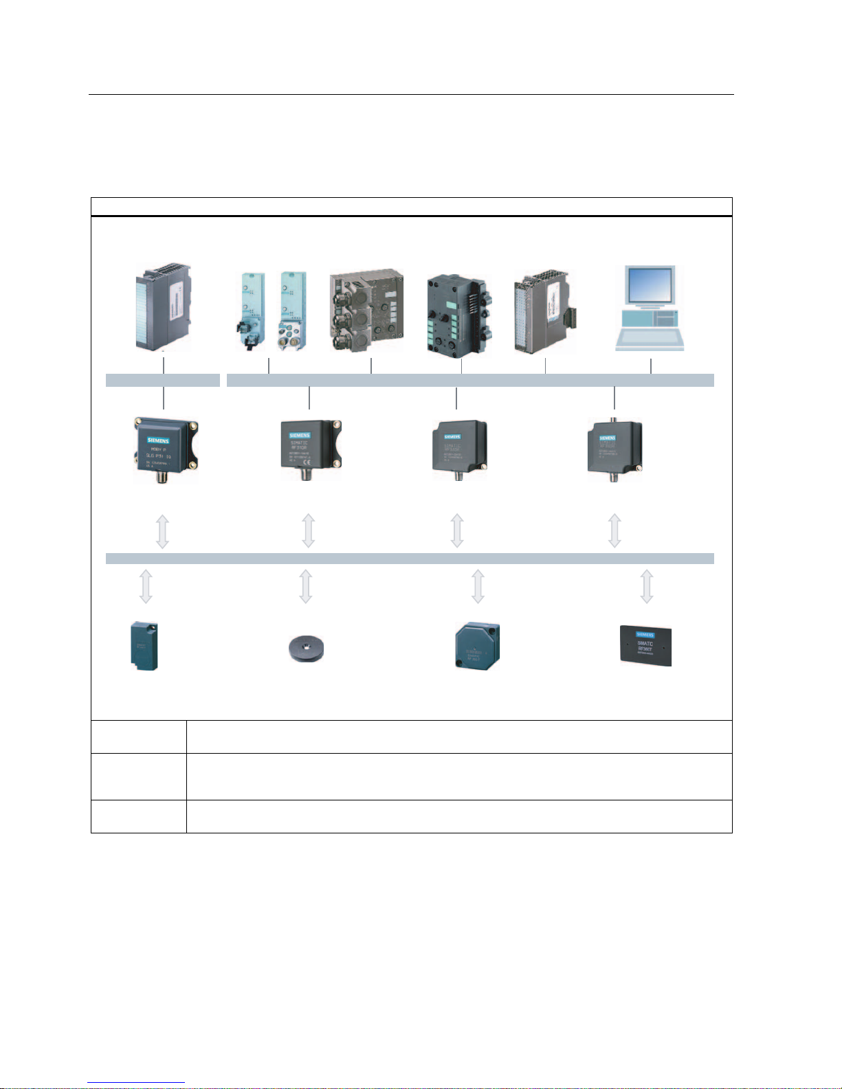
3.2.3 RFID components and their function
RF300 system components
6HULDODV\QFKURQRXVLQWHUIDFH56
5)7
5)7
3RZHUDQGGDWDWUDQVPLVVLRQ0+]
5)5
,46HQVH
,46HQVHLQWHUIDFH
[,46HQVHIRU(70
RQ6ZLWK)&
3&LQWHUIDFHWKLUG
SDUW\3/&
$60IRU
6,0$7,&6
$60IRU
(7;DQG
)&
$60IRU
352),%86'39
5)7
5)7
5)5
5)5
5)5
$60bIRU
352),%86'3
'39
Communication
modules
A communication module (interface module) is used to integrate the RF identification system in
PLC/automation systems.
Reader The reader (read/write device) ensures inductive communication, supplies power to the transponder,
and handles the connection to the various PLCs (e.g. SIMATIC S7) through the communication module
(e.g. ASM 475).
Transponder The transponder (data memory) stores all data relevant to the production process and is used, for
example, instead of barcode.
Conventions
The RF310R and RF340R readers are equipped with an integral antenna, whereas the
RF350R reader is operated over an external antenna. In this system manual, the term
"Reader" is used throughout even where it is actually referring to the antenna of the reader.

System overview
3.2 RF300
SIMATIC RF300
System Manual, Release 04/2006, J31069 D0166-U001-A2-7618
3-5
3.2.4 Technical data
RFID system RF300
Type Inductive identification system for industrial
applications
Transmission frequency data/energy 13.56 MHz
Memory capacity 20 bytes up to 32 KB user memory (r/w)
4 bytes fixed code as serial number (ro)
Memory type EEPROM / FRAM
Write cycles EEPROM: > 100 000
FRAM: Unlimited
Read cycles Unlimited
Data management Byte-oriented access
Data transfer rate Transponder-Reader 3 KB/s (approx.)
Read/write distance (system limit; depends on
reader and transponder)
Up to 0.1 m
Operating temperature Reader: -25°C to +70°C
Transponder: -40°C to +85°C
Degree of protection Reader: IP 65
Transponder: > IP 67
Can be connected to SIMATIC S7-300, Profibus DP V1,
PC
1)
, non-Siemens PLC 1)
Special features High noise immunity
Compact components
Extensive diagnostic options
A reader with IQ-Sense interface
Approvals ETS 300 330 (Europe)
FCC Part 15 (USA), UL/CSA (available soon)
CE
1) By means of RS 422 interface and 3964R protocol

System overview
3.2 RF300
SIMATIC RF300
3-6 System Manual, Release 04/2006, J31069 D0166-U001-A2-7618

SIMATIC RF300
System Manual, Release 04/2006, J31069 D0166-U001-A2-7618
4-1
RF300 system planning
4
4.1 4.1 Fundamentals of application planning
4.1.1 Selection criteria for SIMATIC RF300 components
Assess your application according to the following criteria, in order to choose the right
SIMATIC RF300 components:
• Transmission distance (read/write distance)
• Tracking tolerances
• Static or dynamic data transfer
• Data volume to be transferred
• Speed in case of dynamic transfer
• Metal-free rooms for transponders and readers
• Ambient conditions such as relative humidity, temperature, chemical impacts, etc.
 Loading...