


 Loading...
SIBAG HSD 3.0
High Speed Diverter
Service Manual
Document No.: 747-01695, Rev. 03

SIBAG HSD 3.0 |
Service Manual |
|
|
Information in this document is subject to change without notice. No part of this document may be reproduced or transmitted in any form or by any means, electronic or mechanical, for any purpose, without the express written permission of Siemens Logistics LLC.
2021 Siemens Logistics LLC. All rights reserved.
This document contains confidential information, trade secrets and/or know-how which is the property of Siemens Logistics LLC, and may not be disclosed to any third party without the written permission of Siemens Logistics LLC.
Product and company names herein may be the trademarks of their respective owners.
Siemens Logistics LLC 2700 Esters Blvd. Suite 200B
DFW Airport, TX 75261 www.siemens-logistics.com
972-947-7100
1-800-938-7378 (Parts and Service)
Important: Prior to operating any of the equipment or performing any of the maintenance procedures described within this manual, it is strongly recommended that the operator and maintenance technician read the information provided within the applicable sections of this manual. All personnel shall pay particular attention to the notes, cautions, warnings, and dangers presented in this manual and posted on or in the area of the equipment. This equipment has been designed for use by trained and qualified operators. Every possible effort to prevent injury to the operator or maintenance personnel has been taken in the preparation of this manual. Damage to the equipment is
possible when the procedures contained within this manual are not followed.
Revision History
Revision |
Date |
Description |
|
|
|
01 |
2020-March-05 |
Updated telegram structure, added Ethernet/IP configuration, updated spare |
|
|
parts list updated HMI screens, added TIA Profinet configuration |
02 |
2020-September-10 |
Updated control panels |
03 |
2021-March-03 |
Updated control panels |
ii
Document No.: 747-01695, Rev. 03
2021-March-03

Service Manual |
SIBAG HSD 3.0 |
|
|
Warranty
Goods and Services
Siemens Logistics LLC warrants that the Goods and/or services as set forth in the Sales Agreement and Proposal and sold by Siemens Logistics LLC to Purchaser will be free from defects in material and workmanship for a period of: one (1) year from the date of (i) completion of installation, (ii) Purchaser acceptance, or (iii) beneficial use; or two thousand hours of operation; whichever occurs first (“Warranty Period”), subject to the following terms and conditions. Where someone other than Siemens Logistics LLC installs the Goods, the Warranty Period will commence with shipment of the Goods. Siemens Logistics LLC’s obligation under the warranty is limited to repairing or replacing, at Siemens Logistics LLC’s option, F.O.B. manufacturing plant, any part of the Goods found to be defective within the Warranty Period.
The warranty obligation is conditioned upon receipt by Siemens Logistics LLC of prompt written notice of the claimed defect, including a description of the defect and its discovery, and the opportunity for Siemens Logistics LLC to inspect the Goods in Purchaser's facility.
The warranty obligation does not include costs of labor or other charges incurred in removing or reinstalling parts; and does not apply to Goods damaged by misuse, abuse, neglect or accident or to Goods which have been improperly applied, installed, adjusted, operated, maintained, repaired or altered by persons other than Siemens Logistics LLC.
If Siemens Logistics LLC fails to repair or replace any defective Goods under warranty within a reasonable time, then Siemens Logistics LLC shall be liable to Purchaser for the lesser of (1) the reasonable costs of repair or replacement by a third party or (2) that part of the purchase price of the defective item that shall have been paid by Purchaser, but Purchaser shall not obtain repair or replacement by a third party without giving Siemens Logistics LLC at least twenty (20) days prior written notice, during which time Siemens Logistics LLC may repair or replace the defective item.
Siemens Logistics LLC makes no warranties or representations, nor assumes any obligations with regard to Purchaser’s existing equipment or for any equipment supplied by Purchaser or a third party contracted by Purchaser and used in the Siemens Logistics LLC system and Purchaser assumes full responsibility for the use and operation of such equipment, including compliance with any federal, state and local law, code or regulations
Computer Software and Hardware
For computer software manufactured by Siemens Logistics LLC under the Agreement, Siemens Logistics LLC provides emergency telephone support (1-800-938-7378), which is available 24 hours per day, 7 days per week, at no charge for defective computer software during the Warranty Period. Purchaser’s call will be referred to and promptly handled by a Siemens Logistics LLC technician who will attempt to quickly resolve the problem through telephone discussion. Should troubleshooting efforts by the Siemens Logistics LLC technician determine that assistance by Siemens Logistics LLC Engineering is required, Siemens Logistics LLC will respond in a timely (best effort) manner. Should on-site service be required to resolve a software defect, Siemens Logistics LLC Software Emergency On-Site Service is available, on best effort response, and on a time and expense basis.
For computer hardware supplied by Siemens Logistics LLC under the Agreement, the computer hardware warranty includes next-business day response for defective computer hardware by the computer equipment manufacturer or qualified distributor, from 8 a.m. to 5 p.m. site time, Monday
Document No.: 747-01695, Rev. 03
2021-March-03
i

SIBAG HSD 3.0 |
Service Manual |
|
|
through Friday, during the Warranty Period. If defective computer hardware covered under warranty is detected, replacement parts will be ordered promptly by the equipment manufacturer or qualified distributor and installed upon their arrival. Some parts are warranted by Siemens Logistics LLC and require return to Siemens Logistics LLC for Repair/Replacement. It is the responsibility of Purchaser to reinstall these parts in the computer system as directed by Siemens Logistics LLC.
The warranty does not include updates/upgrades for new versions of computer software and hardware.
The warranty for computer software and hardware will be void and inapplicable to computer software or hardware damaged by misuse, abuse, neglect or accident or to computer hardware or software which has been improperly applied, installed, adjusted, operated, maintained, repaired, modified, changed or altered by persons other than Siemens Logistics LLC or its subcontractors; or to computer software or hardware that is installed or modified by someone other than Siemens Logistics LLC or its subcontractors without the written direction or authority of Siemens Logistics LLC. The computer hardware supplied by Siemens Logistics LLC is suited for an environmentally controlled office environment (e.g., air conditioned, heated and clean office environment) and unless the computer hardware is used in that environment, the computer hardware warranty is null and void for failures.
If the Goods include computer hardware or software acquired from original manufacturers, Siemens Logistics LLC’s obligation will be limited to conveying and transferring to Purchaser any license, interest, rights and/or warranties which Siemens Logistics LLC may obtain from the original manufacturer.
Siemens Logistics LLC does not warrant and is not responsible for warranties or licenses for any, computer hardware or computer software supplied by Purchaser or acquired from a third party by Purchaser and used in the Siemens Logistics LLC system. Purchaser will be responsible for all such licenses and warranties under those circumstances, including any problems detected while the equipment, computer hardware or software is being used for development at Siemens Logistics LLC.
Disclaimer
Siemens Logistics LLC, herein after known as the Company, makes no other warranty of any kind whatsoever expressed or implied and the Company hereby disclaims all warranties of merchantability and fitness for particular purpose. The Company shall in no case be subject to any other obligations or liabilities whatsoever with respect to products or services manufactured or furnished by it or any acts or omissions relating thereto. The remedy provided under this warranty should be the sole, exclusive and only remedy available to Purchaser. Under no circumstances shall the Company be liable for any special, indirect, incidental or consequential damages, expenses, losses or delays howsoever caused.
No statement, representation, agreement or understanding, oral or written, made by any agent, distributor representative or employee of the Company which is not contained in this Warranty will be binding upon the Company unless made in writing and executed by an officer of the Company. Any adjustment made pursuant to this warranty shall not be construed as an admission by the Company that any product was not so warranted.
ii
Document No.: 747-01695, Rev. 03
2021-March-03

Service Manual |
SIBAG HSD 3.0 |
|
|
Contents
1 |
Safety ............................................................................................... |
1 |
1.1 |
Philosophy of Safety ......................................................................... |
1 |
1.2 |
Training............................................................................................. |
2 |
1.3 |
Maintenance Safety Procedures....................................................... |
2 |
1.3.1 |
Safety Tips Prior to Servicing............................................................ |
2 |
1.3.2 |
Safety Tips during Servicing ............................................................. |
3 |
1.3.3 |
Safety Tips after Servicing................................................................ |
4 |
1.4 |
Control of Hazardous Energy (Lockout/Tagout) ............................... |
4 |
1.5 |
Basic Safety Rules............................................................................ |
7 |
1.5.1 |
Basic Maintenance Safety Rules ...................................................... |
8 |
1.6 |
Safety Design Features .................................................................... |
8 |
1.6.1 |
Emergency Stop Devices.................................................................. |
8 |
1.6.2 |
Emergency Stop Procedure.............................................................. |
8 |
1.6.3 |
Spill Guards ...................................................................................... |
9 |
1.6.4 |
Headroom and Aisles........................................................................ |
9 |
1.6.5 |
General Guarding ............................................................................. |
9 |
1.6.6 |
Safety and Warning Labels............................................................... |
9 |
1.6.7 |
Additional Safety References.......................................................... |
12 |
1.7 |
ASME B20.1-2012 Operational & Maintenance Safety .................. |
13 |
2 |
Model Description......................................................................... |
14 |
2.1 |
Description of Operation ................................................................. |
16 |
2.1.1 |
Hardware Overview ........................................................................ |
16 |
2.1.2 |
Diverter Control Panel (DCP) Status Light...................................... |
17 |
2.1.3 |
Basic Operation .............................................................................. |
17 |
2.1.4 |
Human Machine Interface (HMI)..................................................... |
18 |
2.1.5 |
Automatic Mode Operation ............................................................. |
19 |
2.1.6 |
Manual Mode Operation ................................................................. |
20 |
2.1.7 |
Settings Mode Operation ................................................................ |
22 |
3 |
Installation..................................................................................... |
23 |
3.1 |
Installation Sequence and Startup Checklist .................................. |
23 |
3.2 |
Mechanical Installation.................................................................... |
23 |
3.2.1 |
Unloading and Handling.................................................................. |
23 |
3.2.2 |
Unit Identification ............................................................................ |
24 |
3.2.3 |
Installation....................................................................................... |
24 |
3.3 |
Electrical Instructions...................................................................... |
25 |
3.3.1 |
Specifications.................................................................................. |
26 |
3.3.2 |
Installation....................................................................................... |
26 |
3.3.3 |
Setup Using HMI............................................................................. |
27 |
3.4 |
Initial Startup and Operation ........................................................... |
39 |
3.5 |
Installation Inspection Report.......................................................... |
40 |
Document No.: 747-01695, Rev. 03
2021-March-03
iii

SIBAG HSD 3.0 |
Service Manual |
|
|
4 |
Preventive Maintenance............................................................... |
41 |
4.1 |
General........................................................................................... |
41 |
4.2 |
Preventive Maintenance Schedule ................................................. |
42 |
4.3 |
Inspection ....................................................................................... |
43 |
4.3.1 |
Daily Inspections during Normal Operation .................................... |
43 |
4.3.2 |
Monthly Inspections during Non-Operational Hours....................... |
43 |
5 |
Corrective Maintenance ............................................................... |
45 |
5.1 |
General........................................................................................... |
45 |
5.2 |
Lubrication...................................................................................... |
45 |
5.2.1 |
Roller Bearings ............................................................................... |
45 |
5.2.2 |
Pivot Bearings ................................................................................ |
45 |
5.2.3 |
Tie Rod End Bearings .................................................................... |
46 |
5.2.4 |
Servo Gearmotor ............................................................................ |
46 |
5.2.5 |
Drive Pulley .................................................................................... |
47 |
5.3 |
Cleaning ......................................................................................... |
49 |
5.3.1 |
Control Panel.................................................................................. |
49 |
5.4 |
Adjustment...................................................................................... |
49 |
5.4.1 |
Paddle Belt Tracking and Tension.................................................. |
49 |
5.4.2 |
Paddle Position............................................................................... |
50 |
5.4.3 |
Setting Power Supply Output ......................................................... |
51 |
5.4.4 |
Tightening Servo Gearmotor Mount Hardware............................... |
52 |
6 |
Troubleshooting ........................................................................... |
53 |
6.1 |
Mechanical Troubleshooting........................................................... |
53 |
6.1.1 |
Paddle Positioning.......................................................................... |
53 |
6.1.2 |
Servo Gearmotor (Motor) ............................................................... |
54 |
6.1.3 |
Pillow Block Bearings ..................................................................... |
54 |
6.1.4 |
Paddle Nose Rollers and Drive Pulley............................................ |
55 |
6.1.5 |
Paddle Belting ................................................................................ |
58 |
6.2 |
Electrical/Controls Troubleshooting................................................ |
59 |
6.2.1 |
Diverter Faults ................................................................................ |
59 |
6.2.2 |
System Faults (Optional) ................................................................ |
63 |
6.2.3 |
Servo Faults ................................................................................... |
63 |
7 |
Repair ............................................................................................ |
66 |
7.1 |
Torque Values for Hardware .......................................................... |
67 |
7.2 |
Testing HSD Operation .................................................................. |
67 |
7.3 |
High Speed Diverter Top Level Assembly...................................... |
68 |
7.3.1 |
Long Tie Rod .................................................................................. |
68 |
7.4 |
Conveyor Assembly........................................................................ |
71 |
7.4.1 |
Return Roller .................................................................................. |
71 |
7.5 |
Drive Subassembly......................................................................... |
72 |
7.5.1 |
Paddle Assembly (Drive Side)........................................................ |
73 |
7.5.2 |
Servo Gearmotor ............................................................................ |
74 |
7.5.3 |
Pivot Bearings ................................................................................ |
75 |
7.5.4 |
Short Dampened Tie Rod Assembly .............................................. |
76 |
7.5.5 |
Bumpers ......................................................................................... |
78 |
7.6 |
Paddle Assembly............................................................................ |
79 |
|
Document No.: 747-01695, Rev. 03 |
|
iv |
2021-March-03 |
|

Service Manual |
SIBAG HSD 3.0 |
|
|
7.6.1 |
Paddle Belt...................................................................................... |
80 |
7.6.2 |
Paddle Nose Roller......................................................................... |
80 |
7.6.3 |
Paddle Drive Pulley......................................................................... |
81 |
7.7 |
Transition Subassembly.................................................................. |
83 |
7.7.1 |
Paddle Assembly (Non-Drive Side) ................................................ |
83 |
7.7.2 |
Pivot Bearings................................................................................. |
84 |
7.7.3 |
Transition Rollers............................................................................ |
85 |
7.8 |
Control Panel .................................................................................. |
86 |
7.8.1 |
Motor Power Cable ......................................................................... |
86 |
7.8.2 |
Motor Control Cable........................................................................ |
87 |
7.8.3 |
Servo Control Unit and Memory Card Module ................................ |
87 |
7.8.4 |
Reprogram Servo Control Unit........................................................ |
88 |
8 |
Parts............................................................................................... |
92 |
8.1 |
Locating Replacement Parts........................................................... |
92 |
8.2 |
Spare Parts..................................................................................... |
92 |
8.3 |
Ordering Parts................................................................................. |
93 |
8.3.1 |
Business Hours............................................................................... |
93 |
8.3.2 |
Phone Numbers.............................................................................. |
93 |
8.3.3 |
Web Site ......................................................................................... |
93 |
8.3.4 |
Order Processing and Shipping...................................................... |
93 |
8.3.5 |
Repairs............................................................................................ |
93 |
8.3.6 |
Returns ........................................................................................... |
93 |
8.3.7 |
Parts Warranty................................................................................ |
94 |
8.4 |
Illustrations and Parts Lists............................................................. |
94 |
8.4.1 |
HSD 3.0 Top Level Assembly 68.0021.100-XX .............................. |
96 |
8.4.2 |
Tie Rod Assemblies, Long 68.0020.000-38 and 68.0020.001-12... |
98 |
8.4.3 |
Conveyor Assembly 68.0021.114-XX ........................................... |
100 |
8.4.4 |
Drive Subassembly 68.0021.125-XX ............................................ |
102 |
8.4.5 |
Tie Rod Assembly, Dampened 68.0021.000-14 ........................... |
103 |
8.4.6 |
Transition Subassembly 68.0021.121-XX..................................... |
105 |
8.4.7 |
Paddle Assembly 68.0021.110-XX ............................................... |
107 |
8.4.8HSD 3.0 Control Panel 68.0021.201 (120VAC US), 68.0021.202 (24VDC US), 68.0021.203 (24VDC INTL), 68.0021.206 (120VAC
US), 68.0021.207 (24VDC US), Front Door.................................. |
109 |
8.4.9HSD 3.0 Control Panel 68.0021.201 (120VAC US), 68.0021.202 (24VDC US), 68.0021.203 (24VDC INTL), 68.0021.206 (120VAC
|
US), 68.0021.207 (24VDC US), Inside ......................................... |
111 |
8.5 |
Recommended Spare Parts.......................................................... |
115 |
8.5.1 |
Mechanical Spares ....................................................................... |
115 |
8.5.2 |
Electrical Spares........................................................................... |
116 |
9 |
Manufacturers’ Literature........................................................... |
117 |
10 |
Electrical Drawings..................................................................... |
118 |
Document No.: 747-01695, Rev. 03
2021-March-03
v

SIBAG HSD 3.0 |
Service Manual |
|
Safety |
|
|
Figures |
|
|
Figure 1 |
Lockout/Tagout Equipment Examples ............................................... |
6 |
Figure 2 |
Safety and Warning Label Locations ............................................... |
11 |
Figure 3 |
SIBAG HSD 3.0................................................................................ |
14 |
Figure 4 |
HMI Touch Button Symbols ............................................................. |
19 |
Figure 5 |
HMI Automatic Mode........................................................................ |
19 |
Figure 6 |
HMI Manual Mode............................................................................ |
21 |
Figure 7 |
HMI Settings Screen ........................................................................ |
22 |
Figure 8 |
Crated HSD...................................................................................... |
24 |
Figure 9 |
Area Guards..................................................................................... |
25 |
Figure 10 |
HMI Setup Screen............................................................................ |
28 |
Figure 11 |
HMI Setup Options and Setup Speed Screens................................ |
28 |
Figure 12 |
HMI Setup Screen Administrator Button .......................................... |
29 |
Figure 13 |
HMI Admin Screen ........................................................................... |
29 |
Figure 14 |
Hardware Configuration Screen (SIMATIC Manager)...................... |
31 |
Figure 15 |
Config Screens (TIA portal).............................................................. |
32 |
Figure 16 |
EtherNet/IP Configuration (Studio 5000).......................................... |
33 |
Figure 17 |
Tag List (Studio 5000)...................................................................... |
34 |
Figure 18 |
Drive Pulley Oil Level ....................................................................... |
47 |
Figure 19 |
HMI Teach Screens ......................................................................... |
51 |
Figure 20 |
Torquing the Servo Gearmotor Mount Hardware............................. |
52 |
Figure 21 |
Servo Control Unit 320-2 LEDs During Booting ............................... |
60 |
Figure 22 |
Servo Control Unit LEDs during Operation ...................................... |
61 |
Figure 23 |
HSD Top Level Assembly ................................................................ |
68 |
Figure 24 |
Tie Rod Assembly, Long .................................................................. |
70 |
Figure 25 |
Conveyor Assembly ......................................................................... |
71 |
Figure 26 |
Drive Subassembly .......................................................................... |
72 |
Figure 27 |
Tie Rod Assembly, Short Dampened............................................... |
78 |
Figure 28 |
Paddle Assembly ............................................................................. |
79 |
Figure 29 |
Transition Subassembly................................................................... |
83 |
Figure 30 |
Control Panel, Inside........................................................................ |
86 |
Figure 31 |
Sinamics Servo Control Unit and Modules....................................... |
89 |
Figure 32 |
CF Memory Module Card Files ........................................................ |
90 |
Figure 33 |
HSD 3.0 Top Level Assembly 68.0021.100-XX ............................... |
95 |
Figure 34 |
Tie Rod Assemblies, Long 68.0020.000-38 and 68.0020.001-12.... |
98 |
Figure 35 Conveyor Assembly 68.0021.114-XX .............................................. |
99 |
|
Figure 36 Drive Subassembly 68.0021.125-XX ............................................. |
101 |
|
Figure 37 Tie Rod Assembly, Dampened 68.0021.000-14 ............................ |
103 |
|
Figure 38 Transition Subassembly 68.0020.103-XX68.0021.121-XX............ |
104 |
|
Figure 39 Paddle Assembly 68.0021.110-XX ................................................ |
106 |
|
Figure 40 HSD 3.0 Control Panel 68.0021.201 (120VAC US), 68.0021.202 |
|
|
|
(24VDC US), 68.0021.203 (24VDC INTL), 68.0021.206 (120VAC |
|
|
US), 68.0021.207 (24VDC US), Front Door................................... |
108 |
Figure 41 HSD 3.0 Control Panel 68.0021.201 (120VAC US), 68.0021.202 |
|
|
|
(24VDC US), 68.0021.203 (24VDC INTL), 68.0021.206 (120VAC |
|
|
US), 68.0021.207 (24VDC US), Inside .......................................... |
110 |
|
Document No.: 747-01695, Rev. 03 |
|
vi |
2021-March-03 |
|

Service Manual |
SIBAG HSD 3.0 |
|
Safety |
|
|
1 Safety
This manual contains basic guidelines for baggage handling safety, lockout/tagout procedures, safety design features, product features, and general operational and maintenance safety. Its purpose is to improve safety and safety education in the workplace. The safety section is not intended to cover all situations or circumstances, and is not a regulatory publication. Much of the information in this manual comes from the “ASME B20.1 - Safety Standards for Conveyors and Related Equipment” accredited by American National Standards and sponsored by the American Society of Mechanical Engineers (ASME). To request copies of the publication contact: American National Standards Institute, 3 Park Avenue, New York, NY 10016-5990, Phone: 212-591-8500, Fax: 212- 591-8501.
1.1Philosophy of Safety
The philosophy of safety is best described in the following manner:
●Design engineering controls to remove or separate the hazard from people.
●Use administrative controls to separate the hazard from personnel by time or distance.
●Utilize PPE as a final protective measure.
●Warn against the hazard.
The most preferred method of negating a hazard is to design it out of the equipment or installation. Engineering controls, such as guarding, is one of many possible controls against hazards.
●Guards: these are physical barriers that prevent contact. They can be fixed, interlocked, adjustable, or self-adjusting.
●Devices: these limit or prevent access to the hazardous area. These can be presence-sensing devices such as light curtains, pullback or restraint straps, safety trip controls, two-hand controls, or gates.
●Administrative Controls: machine location or distance. This method separates the hazard from the operator’s work area.
●Personal Protective Equipment (PPE): if engineering and administrative controls fail to fully remove the hazard, the final protective measure is PPE.
●Posted warning signs and labels shall be used to remind personnel of the potential hazards. Warnings should also be used to protect against dangerous practices.
Document No.: 747-01695, Rev. 03 |
1 |
2021-March-03 |

SIBAG HSD 3.0 |
Service Manual |
Safety |
|
|
|
Belts and chains moving over pulleys, sprockets, and sheaves create pinch and nip points which must be guarded. These points present a risk of injury if not guarded properly.
●Ensure that all barriers and warning signs are in place to warn personnel about equipment that cannot be guarded.
●Do NOT operate equipment with guards or safety units removed.
●Operate the equipment with TRAINED personnel ONLY.
●Do NOT perform service or maintenance until all power is disconnected and locked out.
1.2Training
In addition to the initial training of personnel (when equipment is first placed into operation), continuous training is required on a scheduled and periodic basis. The purpose of continuous training is to reinforce the importance of safe work practices by ALL employees, including all new hires and transfers working with or around the equipment.
The employer is responsible for providing trained employees knowledgeable in the safe maintenance practices of the baggage handling equipment. Siemens recommends the video presentation “Safety is in Your Hands” as part of each training program. This video addresses the key points relating to safe work practices around baggage handling equipment. To order a copy of this video presentation, contact the Customer Service Department.
1.3Maintenance Safety Procedures
This section describes safety precautions that should be followed before, during and after maintenance and troubleshooting tasks. Since voltages encountered in this equipment can cause lethal shock if mishandled, these safety instructions should be strictly adhered to.
1.3.1Safety Tips Prior to Servicing
●Follow OSHA Control of Hazardous Energy (Lockout/Tagout) procedure before servicing any equipment.
●Utilize OSHA compliant lockout/tagout devices at all pertinent disconnect switches.
●Inform personnel in the area that maintenance tasks are being performed.
●ALWAYS stop the equipment before attempting to clear jams.
●Whenever possible, service electrical equipment with the power "OFF."
●Hot work on electrical equipment is highly hazardous and should only be performed by properly trained personnel familiar with hot electrical work and arc flash protection processes.
2 |
Document No.: 747-01695, Rev. 03 |
|
|
||
2021-March-03 |
|
|
|
Service Manual |
SIBAG HSD 3.0 |
|
Safety |
|
|
●Secure proper tools and wiring diagrams. Be sure that an adequate test instrument is available.
●READ any instructions or test procedures BEFORE attempting them.
●Before beginning work, ensure that power is actually removed by checking various points to ground with test meter. Even though power to the device being serviced is removed, some points of the device may be energized due to interconnections with other equipment. Such areas are appropriately marked.
Yellow wires in a control cabinet remain hot even when the disconnect switch is turned OFF. Use extreme caution when servicing a control cabinet with an outside power source.
●NEVER “ride” or walk on energized conveyors.
1.3.2Safety Tips during Servicing
While working never forget that other pieces of equipment can be involved when a particular START or STOP pushbutton is pressed. For example, a conveyor in a remote area may be energized by a particular operation. Before energizing ANY element of the system it is essential that you be sure to:
●Inform all affected personnel in that area.
●Confirm that all other systems are STILL disabled.
●Stay clear of all chain drives, motor couplings, and belts during equipment operation, especially if guards have been removed.
●Wear personal protective equipment appropriate for the task at all times when performing maintenance duties.
●NEVER wire or tape down limit switches.
●ALWAYS observe the signals of the warning lights.
●Be alert to any deficiency of the equipment.
●NEVER "ride" on a conveyor.
●Do not leave tools or parts where they may be a safety hazard or obstruction.
●Be absolutely certain that all personnel are clear of any moving parts before starting the conveyor system.
●Report all accidents resulting in personal injury or damage to the equipment to the Supervisor.
In the unlikely event of electrocution, do not touch the victim until the high voltage circuit is broken.
Document No.: 747-01695, Rev. 03 |
3 |
2021-March-03 |

SIBAG HSD 3.0 |
Service Manual |
Safety |
|
|
|
1.3.3Safety Tips after Servicing
●Follow OSHA Control of Hazardous Energy (Lockout/Tagout) procedures for the removal of lock out tag out devices.
●When servicing is complete, replace all guards and safety devices; remove test equipment and tools. Remove and properly dispose of any damaged components and close all panels.
●Do not leave tools or parts where they may be a safety hazard or obstruction.
●Finally, remove all lockout/tagout equipment and inform all affected personnel in the area that servicing is completed before restarting equipment.
1.4Control of Hazardous Energy (Lockout/Tagout)
The primary purpose for a lockout/tagout procedure is to protect workers from injury caused by the unexpected energization or start-up of equipment.
Occupational Safety and Health Administration (OSHA) standard 29CFR 1910.147, Appendix A, outlines the minimum requirements for the control of hazardous energy in general industry. It is the opinion of Siemens that this standard applies to all workplaces utilizing powered conveyors. The OSHA standard centers on the control of potentially hazardous energy and how to secure it to prevent harm to employees. The rule requires that energy sources for equipment be turned off or disconnected, and that the switches be locked or labeled with a warning tag. This ensures that the equipment has been shut down for servicing or maintenance and will not reactivate while employees are working on it. The regulation defines servicing and maintenance as covering “lubrication, cleaning or unjamming of machines or equipment... where the employee may be exposed to the unexpected energization or startup of the equipment...” among other things.
We are bringing this to your attention in the event you are not aware of the standard. We urge you to review the applicability and requirements of the standard with respect to your facilities. The lockout/tagout procedure is considered to be just one element of the control procedures for hazardous energy. The employer is responsible for providing procedures that include deenergization of equipment, isolation of energy sources, verification that equipment has been de-energized, and complete diffusion of stored energy.
The standard requires the employer to create an ongoing program of control procedures, equipment specific Lockout/Tagout procedures for each piece of equipment, and employee training by the employer (regardless of training provided by the equipment vendor at the time of sale) to ensure that the purpose and functions of energy controls are understood and applied.
4 |
Document No.: 747-01695, Rev. 03 |
|
|
||
2021-March-03 |
|
|
|

Service Manual |
SIBAG HSD 3.0 |
|
Safety |
|
|
For information regarding the Control of Hazardous Energy (Lockout/Tagout) requirements in the General Industry, refer to 29 CFR 1910 section 147.
●Lockout/tagout should take place before any service or maintenance work begins. Alert affected personnel of power disconnection. Isolate the power source.
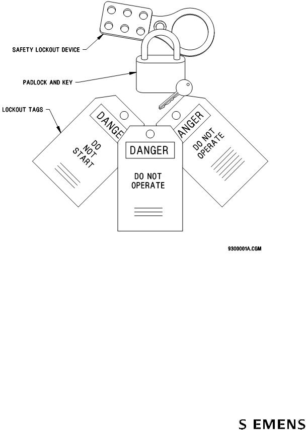
●Attach lockout tags to each lock indicating name of service person, date, contact phone number, and purpose of the lockout.
●Use padlocks with only one key for all lockout purposes. If duplicate keys exist, keep them under strict management supervision.
●Check for stored energy. Test the equipment to be sure that it will not operate. Before beginning work, ensure that power is actually removed by checking various points to ground with test meter. Even though power to the device being serviced is removed, some points of the device may be energized due to interconnections with other equipment. Such areas are appropriately marked.
●The service person who locks and tags a machine must be the one who unlocks it.
●Never remove a lock or tag that is not yours.
●Never lockout or tag equipment for another person.
●If a lock or tag needs to be left on during a shift change, the individual who initiated the lockout shall transfer the lockout/tagout responsibility to an authorized employee of the oncoming shift. If a lockout is left in place by a previous shift and no transfer of responsibility has taken place, assume the equipment is locked or tagged for a good reason; do not remove the lockout. Contact your supervisor or manager who will make the decision on how to proceed.
●Before removing a lockout and energizing the equipment, communicate to all affected personnel in the area that the system is about to be reactivated.
Document No.: 747-01695, Rev. 03 |
5 |
2021-March-03 |
|
SIBAG HSD 3.0 |
Service Manual |
||
|
Safety |
|
|
|
|
|
|
|
|
|
Figure 1 |
Lockout/Tagout Equipment Examples |
|
|
|
|
|
|
|
|
|
|
|
|
6 |
Document No.: 747-01695, Rev. 03 |
|
|
||
2021-March-03 |
|
|
|

Service Manual |
SIBAG HSD 3.0 |
|
Safety |
|
|
1.5Basic Safety Rules
Document No.: 747-01695, Rev. 03 |
7 |
2021-March-03 |

SIBAG HSD 3.0 |
Service Manual |
Safety |
|
|
|
1.5.1Basic Maintenance Safety Rules
The maintenance staff also plays a key role in the overall safety of the material handling equipment. Creating and practicing a preventive approach to safety helps establish an effective safety program.
●Lockout/tagout must take place before any service or maintenance work begins per section 1.4 Control of Hazardous Energy (Lockout/Tagout.
●All maintenance or service is to be performed by qualified, trained personnel only.
●Always report unsafe conditions or anything out of the ordinary to the supervisor.
1.6Safety Design Features
Baggage handling equipment has safety design features for worker protection. Basic baggage handling safety design features are outlined on the pages that follow.
1.6.1Emergency Stop Devices
Illuminated red emergency stop (E-STOP) push-pull buttons, limit switches, emergency pull cords, and other similar emergency stop devices are located throughout the system for operator protection during emergency situations and are for reaction to an incident or hazardous situation where imminent danger to personnel exists.
These emergency stop devices are normally used at or near each potential work station. E-stop devices are also provided at reasonable intervals throughout material handling systems in areas routinely occupied by operations personnel.
E-stop devices are not intended to disable equipment to provide protection for personnel in non-emergency circumstances. For example, maintenance, jam clearing, and/or other similar activities require adherence to established lockout/tagout procedures.
E-stops ideally control all movement visible from and related to the equipment or location of the control device.
1.6.2Emergency Stop Procedure
Emergency Stop and restart the entire system as follows:
1.Activate any E-STOP pushbutton (this will stop the associated conveyors).
2.Fix the reason for pushing the E-STOP pushbutton.
3.Reset the activated E-STOP pushbutton.
4.Pull the activated E-STOP pushbutton and restart the system as normal.
8 |
Document No.: 747-01695, Rev. 03 |
|
|
||
2021-March-03 |
|
|
|

Service Manual |
SIBAG HSD 3.0 |
|
Safety |
|
|
1.6.3Spill Guards
Many portions of material handling equipment run overhead and around areas accessible to personnel. It is important that these areas be protected with spill guards or other guarding design features.
1.6.4Headroom and Aisles
When conveyors run above aisles, passageways or exits designated as fire exit pathways, warnings will be provided if head clearance is less than 6 feet 8 inches (2 meters). The clearance of 6 feet 8 inches (2 meters) is measured from the floor to the lowest part of the conveyor or guards. Other aisles or passageways with less than 6 feet 8 inches (2 meters) clearance will be protected by safety tape and warning signs.
In designated aisleways, all moving equipment parts to an elevation of 8 feet (2.4 meters) will be guarded.
1.6.5General Guarding
When necessary for the proper protection of workers, it is required that areas be properly guarded where equipment meets or exposed moving parts present a potential hazard. It is recommended that warning and caution signs be positioned in the employees’ line of sight.
Guarding shall never be removed or disabled for normal operations. Removal of guarding shall only be done in accordance with established maintenance and lockout/tagout procedures.
1.6.6Safety and Warning Labels
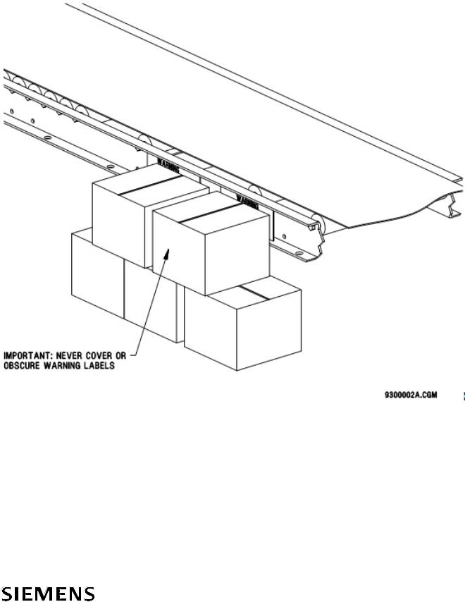
Warning and safety labels are factory installed by the manufacturer or applied after installation. Siemens equipment has safety labels attached with messages warning of potential risks. These labels are located to be useful in any application. Individual installations may have a unique need for additional labels in other mounting locations. Therefore, more of the standard labels are readily available.
These labels and signs may need to be supplemented by other warnings of individual design that may be obtained from local sources or nationally distributed catalogs.
DANGER: Indicates an imminently hazardous situation that, if not avoided, will result in death or severe injury. The use of danger labels is limited to the most extreme situations
WARNING: Indicates a potentially hazardous situation that, if not avoided, could result in death or severe injury
Document No.: 747-01695, Rev. 03 |
9 |
2021-March-03 |

SIBAG HSD 3.0 |
Service Manual |
Safety |
|
|
|
CAUTION: Indicates a potentially hazardous situation that, if not avoided, will result in minor or moderate injury. It may also be used to alert against unsafe practices.
DANGER or WARNING should not be considered for property damage accidents unless personal injury risk appropriate to these levels is also involved. CAUTION is permitted for property-damage-only accidents. Sign placement shall be in the immediate vicinity of the hazard, readily visible so the viewer can recognize the hazard and take appropriate action.
Safety Signs and Labels Verification: On a quarterly basis, walk through the entire material handling system and make sure that all safety signs and labels are clearly legible and in good condition. Particularly if the system has been reconfigured, verify that the signs and labels are still in the proper locations. If there is a problem with any sign or label, reorder and replace it according to the following identification and ordering pages.
10 |
Document No.: 747-01695, Rev. 03 |
|
|
||
2021-March-03 |
|
|
|
|
Service Manual |
SIBAG HSD 3.0 |
||
|
|
|
Safety |
|
|
|
|
|
|
|
Figure 2 |
Safety and Warning Label Locations |
|
|
|
|
|
|
|
|
|
|
|
|
Document No.: 747-01695, Rev. 03 |
11 |
2021-March-03 |

SIBAG HSD 3.0 |
Service Manual |
Safety |
|
|
|
1.6.7Additional Safety References
ANSI – American National |
B 11.19 Performance Requirements for Risk Reduction Measures: |
||
Standards Institute |
Safeguarding and other Means of Reducing Risk (AMT) |
||
|
B 20.1 Safety Standard for Conveyors (ASME) |
||
|
Z 535.1 Safety Colors (NEMA) |
||
|
Z 535.2 Environ. and Facility Safety Signs (NEMA) |
||
|
Z 535.3 Criteria for Safety Symbols (NEMA) |
||
|
Z 535.4 Product Safety Signs and Labels (NEMA) |
||
|
Z 535.5 Safety Tags and Barricade Tapes (NEMA) |
||
CEMA – Conveyor Equipment |
102 |
Terms and Definitions |
|
Manufacturer's Association |
201 |
Safety Label Brochure |
|
|
402 |
Belt Conveyors |
|
OSHA – Occupational Safety and |
|
|
|
Health Administration |
|
|
|
Subpart C (1917) Cargo Handling |
1917.43 |
Powered Industrial Trucks |
|
Gear and Equipment |
1917.44 |
General Rules Vehicles |
|
|
1917.45 |
Cranes and Derricks |
|
|
1917.46 |
Crane Load and Limit Devices |
|
|
1917.48 |
Conveyors |
|
|
1917.49 |
Spouts, Chutes, Hoppers, Etc. |
|
Subpart D (1910) Walking/Working |
1910.21 |
Scope and Definitions |
|
Surfaces |
1910.22 |
General Requirements |
|
|
1910.23 |
Ladders |
|
|
1910.25 |
Stairways |
|
|
1910.28 |
Duty to have fall protection and falling object |
|
|
protection |
|
|
|
1910.29 |
Fall protection systems and falling object protection— |
|
|
criteria and practices |
||
|
1910.30 |
Training requirements |
|
Subpart J (l910) General |
1910.144 |
Safety Color Codes for Marking Physical Hazards |
|
Environmental Controls |
1910.145 |
Specifications for Accident Prevention Signs and Tags |
|
|
1910.147 |
The Control of Hazardous Energy (Lockout/Tagout) |
|
Subpart N (1926) Cranes, Derricks, |
1926.551 |
Cranes and Derricks |
|
Hoists, Elevators, and Conveyors |
1926.552 |
Material Hoists |
|
|
1926.553 |
Base Mounted Drum Hoists |
|
|
1926.554 |
Overhead Hoists |
|
|
1926.555 |
Conveyors |
|
Subpart O (1910) Machinery and |
1910.211 |
Definitions |
|
Machine Guarding |
1910.212 |
General Requirements for All Machines |
|
|
1910.219 |
Mechanical Power-Transmission Apparatus |
|
Subpart S (1910) Electrical |
1910.301 |
Introduction |
|
|
1910.302 |
Electric Utilization Systems |
|
|
1910.303 |
General |
|
|
1910.304 |
Wiring Design and Protection |
|
|
1910.305 |
Wiring Methods, Components, and |
|
|
Equipment-General Use |
||
|
1910.307 |
Hazardous Locations |
|
|
1910.308 |
Special Systems |
|
NFPA – National Fire Protection |
70E - Standard for Electrical Safety in the Workplace |
||
Association |
79 - Electrical Standard for Industrial Machinery |
||
12 |
Document No.: 747-01695, Rev. 03 |
|
|
||
2021-March-03 |
|
|
|
Service Manual |
SIBAG HSD 3.0 |
|
Safety |
|
|
1.7ASME B20.1-2012 Operational & Maintenance Safety
Portions of the ANSI “Safety Standards of Conveyors and Related Equipment” (ASME B20.1-2012) relate to operational and maintenance personnel.
Introduction
Accidents resulting from the manual handling of materials have been reduced by the use of conveying and other forms of mechanical handling equipment. A further reduction in the accident rate can be gained by following safe practices in the design, construction, installation, operation, and maintenance of such equipment.
The design and installation of conveyors and conveyor systems should be supervised by qualified engineers. Likewise, the maintenance of conveyors and systems should be supervised by trained personnel.
The purpose of this standard is to present certain guides for the design, construction, installation, operation, and maintenance of conveyors and related equipment.
Those portions of this standard relating to maintenance and operation procedures are fully as important as those relating to design and installation. The best design features may be negated by faulty maintenance and operating practices. It is important that operating and maintenance personnel be instructed in recognizing hazards and pertinent safety precautions.
5.2Maintenance (Repair)
a.Maintenance and service shall be performed by qualified and trained personnel.
b.Where lack of maintenance would cause a hazardous condition, the user shall establish a maintenance program to ensure that conveyor components are maintained in a condition that does not constitute a hazard to personnel.
c.No maintenance shall be performed when a conveyor is in operation except as outlined in 5.3 and 5.4.
d.When a conveyor is stopped for maintenance or repair purposes, the starting devices, prime movers, or powered accessories shall be locked out or tagged out in accordance with a formalized procedure designed to protect all persons or groups involved with the conveyor against unexpected restart. Personnel should be alerted to the hazard of stored energy, which may exist after the power source is locked out. Refer to ANSI Z244.1-1982, American National Standard for Personnel Protection – Lockout/Tagout of Energy Sources – Minimum Safety Requirements and OSHA 29 CFR 1910.147 The Control of Hazardous Energy (Lockout/Tagout).
e.All safety devices and guards shall be replaced before starting equipment for normal operations.
5.3Lubrication
a.Conveyors shall not be lubricated while in operation unless it is impractical to shut down for lubrication. Only trained and qualified personnel who are aware of the hazard of a conveyor in motion shall be allowed to lubricate a conveyor that is operating.
b.Where the drip of lubricants or process liquids on the floor constitutes a hazard, drip pans or other means of eliminating the hazard shall be provided.
5.4Adjustment or Maintenance
When adjustment or maintenance is required while equipment is in operation, only trained and qualified personnel who are aware of the hazard of the conveyor in motion shall be allowed to make the adjustment or perform the maintenance or service.
5.9.1General Requirements of Guarding
5.9.1.3Guarding Exceptions. Wherever conditions prevail that would require guarding under these standards but such guarding would render the conveyor unusable, prominent warnings shall be provided in the area or on the equipment in lieu of guarding.
5.9.1.4Maintenance of Guards and Safety Devices. Guards and safety devices shall be maintained in a serviceable and operational condition. Warning signs provided in accordance with 5.9.1.3 shall be maintained in a legible, operational condition.
5.12Operation
a.Only a trained person shall be permitted to operate a conveyor. Training shall include instruction in operation under normal conditions and emergency situations.
b.Where safety is dependent upon stopping devices or starting devices or both, they shall be kept free from obstructions to permit ready access.
c.The area around loading and unloading points shall be kept clear of obstructions that could endanger personnel.
d.No person shall ride on a conveyor, unless it is a conveyor engineered for that purpose.
e.Personnel working on or near a conveyor shall be instructed as to the location and operation of pertinent stopping devices.
f.A conveyor shall be used to transport only loads it is designed to handle safely.
g.Under no circumstances shall the safety characteristics of the conveyor be altered without proper authorization from the manufacturer.
h.Routine inspections and corrective maintenance measures shall be conducted to ensure that all guards and safety features are retained and function properly.
i.Personnel should be alerted to the potential hazard of entanglement in conveyors caused by such items such as long hair, loose clothing, and jewelry.
j.Conveyors shall not be maintained or serviced while in operation unless proper maintenance or service requires the conveyor to be in motion. In which case, personnel shall be made aware of the hazards and how the task may be safely accomplished.
NOTE: Contact the American Society of Mechanical Engineers at the address shown above for the complete ASME B20.1-2012.
NOTE: These excerpts are printed with the permission of ASME.
Document No.: 747-01695, Rev. 03 |
13 |
2021-March-03 |
SIBAG HSD 3.0 |
Service Manual |
Model Description |
|
|
|
2 Model Description
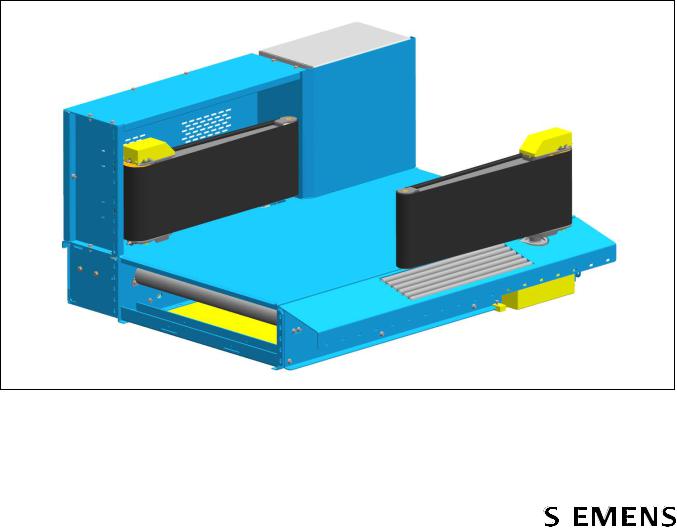
The SIBAG High Speed Diverter 3.0 (HSD 3.0) is a device with two paddles mounted on a horizontal belt conveyor used to divert the flow of one of several bags by moving the paddles into the baggage stream. For better baggage flow, the paddles are equipped with actively driven belts. The HSD 3.0 is designed to be an integral part of a mainline belt conveyor sort system. The activated paddles of the diverter form a 45 degree vertical powered belt wall for the transfer of luggage from a main sort line to a pier chute or take-away conveyor. The baggage contacts the diverter in a smooth, non-destructive manner, which minimizes the impact forces applied during the sort process.
The HSD 3.0 is designed to handle virtually all types of normal baggage, but it is not intended to process hazardous or volatile materials and liquids.
Figure 3 SIBAG HSD 3.0
14 |
Document No.: 747-01695, Rev. 03 |
|
|
||
2021-March-03 |
|
|
|

Service Manual |
SIBAG HSD 3.0 |
|
Model Description |
|
|
A single servo gearmotor efficiently powers the diverting action of the HSD 3.0, rotating the paddles 45 degrees across the conveyor belt between their diverting and non-diverting positions. It delivers motion to the pivot shaft of both the drive side and non-drive side paddles simultaneously via a tie rod assembly. A drive pulley powers the belt on each paddle.
When system control determines a need, the HSD 3.0 is energized, and the paddle belts begin running. Diverter position is determined by the diverter control panel by evaluating the output of the servo gearmotor encoder.
The HSD 3.0 is available in the configurations listed in Table 1. This manual provides service and parts information for all versions.
Table 1 Available HSD 3.0 Versions
Part Number |
Conveyor Width |
Transition Width |
Hand |
|
|
|
|
68.0021.100-01 |
39 in. |
7 in. |
Left |
68.0021.100-02 |
39 in. |
7 in. |
Right |
68.0021.100-03 |
39 in. |
10 in. |
Left |
68.0021.100-04 |
39 in. |
10 in. |
Right |
68.0021.100-05 |
1000mm |
180mm |
Left |
68.0021.100-06 |
1000mm |
180mm |
Right |
68.0021.100-07 |
1000mm |
250mm |
Left |
68.0021.100-08 |
1000mm |
250mm |
Right |
68.0021.100-09 |
1050mm |
180mm |
Left |
68.0021.100-10 |
1050mm |
180mm |
Right |
68.0021.100-11 |
1050mm |
250mm |
Left |
68.0021.100-12 |
1050mm |
250mm |
Right |
68.0021.100-13 |
45 in. |
7 in. |
Left |
68.0021.100-14 |
45 in. |
7 in. |
Right |
68.0021.100-15 |
45 in. |
10 in. |
Left |
68.0021.100-16 |
45 in. |
10 in. |
Right |
68.0021.100-17 |
1200mm |
180mm |
Left |
68.0021.100-18 |
1200mm |
180mm |
Right |
68.0021.100-19 |
1200mm |
250mm |
Left |
|
|
|
|
68.0021.100-20 |
1200mm |
250mm |
Right |
Document No.: 747-01695, Rev. 03 |
15 |
2021-March-03 |

SIBAG HSD 3.0 |
Service Manual |
Model Description |
|
|
|
2.1Description of Operation
The HSD 3.0 uses a Sinamics drive configuration with a Siemens programmable servo control unit CU320-2 and two separate output channels (axles), one for servo-positioning of the paddles (SERVO) and one for asynchronous movement of the paddle-belts (VECTOR).
The main supply voltage is separate from the control voltage. Disconnect and lock out/tag out both the main supply voltage and control voltage before performing maintenance.
There is a Human Machine Interface (HMI) on the control panel door to select manual or auto modes or to change settings.
A high level PLC with user-defined parameters is used which selects between common signal exchanges wired to communicate via Digital I/O, PROFIBUS, PROFINET, or Ethernet/IP interface (depending on how the HSD 3.0 was ordered).
NOTE: The HSD 3.0 cannot hold the paddles in position when the power is off. For that reason, the unit should always be powered unless maintenance is being performed. If the unit needs to be removed from service, it should be disabled at the PLC level (control room).
2.1.1Hardware Overview
The HSD 3.0 is controlled by a Sinamics Drive System with programmable servo control module. The control module is comprised of the following:
●Servo Control Unit Sinamics S120 CU320-2
●Smart Line Servo Power Module
●Double Servo Motor Module
●Servo gearmotor with absolute encoder for positioning
●Asynchronous motors without encoder for paddle belts
●Basic Operator Panel BOP20
16 |
Document No.: 747-01695, Rev. 03 |
|
|
||
2021-March-03 |
|
|
|

Service Manual |
SIBAG HSD 3.0 |
|
Model Description |
|
|
2.1.2Diverter Control Panel (DCP) Status Light
A color indicator light shows the HSD status according to the following table.
Table 2 |
DCP Status Light Colors |
||
|
|
|
|
|
Color |
|
Definition |
|
|
|
|
|
Green |
|
Steady – Ready for automatic operation |
|
|
|
Flashing – Ready for manual operation |
|
Red |
|
Steady – Stopped or E-stopped |
|
Yellow |
|
Steady – Fault |
|
|
|
Flashing – Saving adjusted settings |
|
Blue |
|
Steady – Motor overload |
2.1.3Basic Operation
In the BHS PLC operation, a bag arriving at the tracking photocell (provided by BHS integrator), located at least 12 inches (305mm) upstream of the HSD 3.0 on the conveyor bed, is checked to see if it requires diverting from the main conveyor line. Once a determination is made, the diverter responds as outlined below.
If the bag is to be diverted, one of the following occurs:
●If the diverter is in the RETRACTED position, the paddle belt drive pulleys are started via a maintained PADDLE BELT RUN signal when the tracking photocell is blocked, and when the bag is tracked nearly to the pivot point of the first paddle, the servo gearmotor is energized via a leading edge trigger of the EXTEND PADDLES signal so that the diverter is moved to the EXTENDED position which will allow the bag to divert.
●If the diverter is already in the EXTENDED position, the paddle belt drive pulleys are started when the tracking photocell is blocked, and the paddles remain stationary, allowing the bag to divert.
After either case, the paddle belt motors shall continue to run for at least 20 seconds to allow for following sort operations without restarting the motors. This 20 second period is reset as each new bag passes the 12 inches (305mm) upstream tracking photocell. If no sort action is required during those 20 seconds, the HSD 3.0 paddle belt drive pulleys are deactivated by the PLC removing the PADDLE BELT RUN signals until the next time they are needed.
Document No.: 747-01695, Rev. 03 |
17 |
2021-March-03 |

SIBAG HSD 3.0 |
Service Manual |
Model Description |
|
|
|
If the bag does not require diverting, the following occurs:
●If the diverter is in the EXTENDED position when the bag is tracked to nearly the pivot point of the first paddle, the servo gearmotor is energized via a leading edge trigger of the RETRACT PADDLES signal so that the diverter will return to the RETRACTED position which allows the bag to pass through. The paddle belt drive pulleys do not need to be activated for this action.
●If the diverter is already in the RETRACTED position, the motors remain off and the paddles remain stationary, allowing the bag to pass through.
Ideally, the HSD 3.0 motors are energized only when a sort action is required. Additionally, the paddles are actuated to a different position only when required to do so. If bag spacing is not adequate no sort action shall be attempted. The HSD 3.0 will complete a position change actuation in approximately 310 ms (or 400 ms for widths over 1050 mm)
NOTE: Reliable operation of the diverter at chutes or parallel takeaways requires a minimum “gap” between bags of at least 24 inches (610 mm). The average length of each piece of baggage plus the 24 inch (610 mm) gap defines the bag window size.
The PLC should also monitor for fault conditions in the HSD 3.0. If the HSD 3.0 does not complete an intended position change, the Servo Control Unit will indicate a fault condition.
The HMI and the BOP20 will display the code for any alarms or faults. The list of alarms and faults can be found in the Siemens Sinamics S List Manual.
The HSD 3.0 can be operated in three different modes, selected on the HMI located on the HSD 3.0 Diverter Control Panel (DCP):
●Automatic
●Manual
●Settings
2.1.4Human Machine Interface (HMI)
There is a Human Machine Interface (HMI) on the control panel door to select manual or auto modes or to change settings. Both manual and settings modes are available without the high level PLC running.
All screens have the following touch buttons at the bottom of the screen for operation and navigation:
18 |
Document No.: 747-01695, Rev. 03 |
|
|
||
2021-March-03 |
|
|
|
|
Service Manual |
|
SIBAG HSD 3.0 |
|
|
|
Model Description |
|
|
|
|
|
Figure 4 HMI Touch Button Symbols |
|
|
|
AUTO MANUAL SETTINGS |
DIAGNOSTICS RESET BACK |
|
|
|
|
|
Some screens can only be accessed with administrator-provided login privileges. See section 3.3.3 Setup Using HMI.
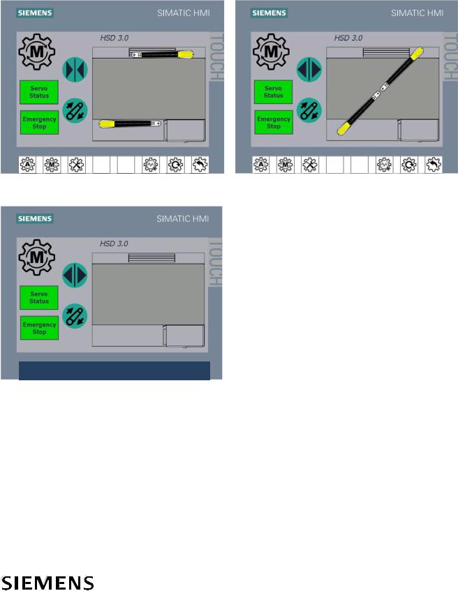
2.1.5Automatic Mode Operation
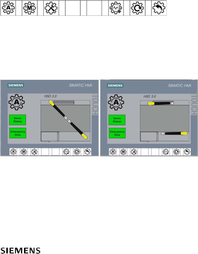
Touch the Auto  button on the HMI on the door of the DCP for automatic operation. The HMI displays the HSD paddles in their current positions. Servo Status and Emergency Stop buttons indicate the status of the servo and e-stop.
Figure 5 |
HMI Automatic Mode |
|
|
|
RH, Extended |
RH, Retracted |
|||
|
|
|
|
|
|
|
|
|
|
|
|
|
|
|
Table 3 |
Servo Status and Emergency Stop Button Status Colors |
||
|
|
|
|
|
Button and Color |
Description |
|
|
|
|
|
|
Servo Status Green |
Running; no servo fault |
|
|
Servo Status Grey |
E-stop activated; no servo fault |
|
|
Servo Status Yellow |
Servo fault present |
|
|
Emergency Stop Green |
Running; no estop activated |
|
|
Emergency Stop Red |
E-Stop activated |
|
NOTE: Divert All Operation: If there is a need to divert all bags off of the mainline, the Baggage Handling System (BHS) logic controller will need to provide the signal to maintain the paddles in the extended position while the diverter remains in the Automatic mode.
Document No.: 747-01695, Rev. 03 |
19 |
2021-March-03 |

SIBAG HSD 3.0 |
Service Manual |
Model Description |
|
|
|
In Automatic mode, touch the Reset button to reset a fault after it has been cleared.
There are two methods of controlling the HSD 3.0 in Automatic mode:
●Common input/output exchange through the use of 120 VAC or 24 VDC control relays. These relays are located in the HSD 3.0 control panel and are wired to the CU320-2 servo control unit.
●Network communications over PROFIBUS, PROFINET, or EtherNet/IP
There is a parameter in the HSD 3.0 drives that will select the method of control in Automatic mode. This can be adjusted by using the HMI Settings screens, Siemens Starter program, or by using the Basic Operator Panel on the HSD 3.0 drive. If this parameter is set to 0, the control relays will operate the HSD 3.0. A setting of 1 will enable the PROFIBUS communications, etc.
NOTE: When one of the network communication types is selected, it is still necessary to make a direct electrical connection to the e-stop safety relay for a safety stop to occur.
2.1.6Manual Mode Operation
Touch the Manual  button on the HMI on the door of the DCP for manual operation. The HMI displays the HSD paddles in their current position. When the HSD paddles are not in a known position (in between extend or retract), they are not shown.
NOTE: When the HSD paddles are not shown, press the Retract button to retract the paddles to the retract position, as shown in Figure 6 (LH, In Between). This displays the paddles on the HMI screen and allows the BHS controller to know the paddle positions when the HSD is returned to the Automatic mode.
In this mode, touching the Extend/Retract 
 and Paddle Belt
  buttons manually operate the HSD. Touching the Extend/Retract buttons will return the paddles to the extend/retract positions saved in the memory. Touching the Paddle Belt button will run the paddle belt. In this mode, the diverter will not respond to BHS signals EXTEND PADDLES, RETRACT PADDLES, or PADDLE BELT RUN.
NOTE: Divert All Operation: If there is a need to divert all bags off of the mainline, the Baggage Handling System (BHS) logic controller will need to provide the signal to maintain the paddles in the extended position while the diverter remains in Automatic mode. Because Manual mode replaces the automatic function signals from the BHS controller, the HSD 3.0 would no longer have the ability to turn off the motors in the event of a cascade or normal timeout situation. For this reason, it is not acceptable to use Manual mode for the purpose of sustained Divert All operation.
20 |
Document No.: 747-01695, Rev. 03 |
|
|
||
2021-March-03 |
|
|
|
Service Manual |
|
SIBAG HSD 3.0 |
|||
|
|
|
|
Model Description |
|
|
|
|
|
|
|
Figure 6 |
HMI Manual Mode |
|
|
|
|
LH, Retracted |
LH, Extended |
||||
|
|
|
|
|
|
|
|
|
|
|
|
LH, In Between
Document No.: 747-01695, Rev. 03 |
21 |
2021-March-03 |
SIBAG HSD 3.0 |
Service Manual |
Model Description |
|
|
|
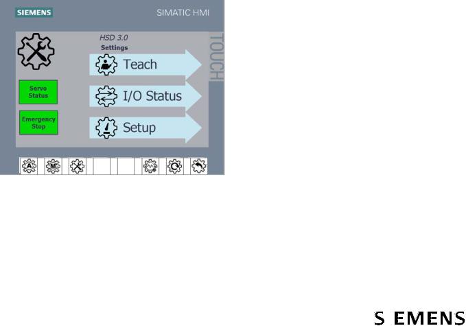
2.1.7Settings Mode Operation
Touch the Settings  button on the HMI on the door of the DCP for settings mode. In this mode the Teach, I/O Status, and Setup buttons on the HMI are enabled:
●Teach is used to define new end positions for the servo cycle commands. The paddle extend and retract positions are factory configured, but reconfiguring them might be necessary if the mechanism has been adjusted or repaired. See section 5.4.2 Paddle Position.
●I/O Status is used to view the status of the outputs from the servo control unit (first 6) and inputs to the servo control unit (last 4) for diagnostics and troubleshooting. This screen is accessible without entering a password.
●Setup is used to set up the HSD by Siemens during manufacturing to configure the communication type, conveyor width, and diverter hand. It is used during installation commissioning by the system integrator to set the speed. See section 3.3.3.2 Set Mainline Conveyor Belt Speed and Other Options.
In this mode, the diverter will not respond to BHS signals EXTEND PADDLES,
RETRACT PADDLES, or PADDLE BELT RUN.
Figure 7 HMI Settings Screen
|
|
|
|
22 |
Document No.: 747-01695, Rev. 03 |
|
|
|
|||
|
2021-March-03 |
|
|
|
|||
Loading...