


SINVERT 350, SINVERT 420 and SINVERT 500 TL
Operating Manual – 11/2009
SINVERT
Answers for environment.
1

Photovoltaic
SINVERT
Introduction
SINVERT 350, SINVERT 420 and
SINVERT 500 TL |
Description |
|
|
|
|
||
|
|
|
|
Hardware operation
Alarm and fault messages
Support
1
2
3
4
5

Safety instructions
These Operating Instructions contain information which you should observe to ensure your own personal safety as well as to protect the product and connected equipment. The notices referring to your personal safety are highlighted in the manual by a safety alert symbol. Notices referring only to equipment damage have no safety alert symbol. Warnings are shown in descending order according to the degree of danger as follows.
 DANGER
indicates that death or serious injury will result if proper precautions are not taken.
 WARNING
indicates that death or serious physical injury may result if proper precautions are not taken.
 CAUTION
with a safety alert symbol indicates that minor personal injury can result if proper precautions are not taken.
CAUTION
without a safety alert symbol indicates that damage to property may result if proper precautions are not taken.
CAUTION
indicates that an unwanted result or state may occur if the relevant instruction is not observed.
In the event of a number of levels of danger prevailing simultaneously, the warning corresponding to the highest level of danger is always used. A warning that uses a safety alert symbol indicating possible personal injury may also include a warning relating to material damage.
Qualified personnel
The associated equipment / system may only be set up and operated in conjunction with this documentation. The equipment / system may only be commissioned and operated by qualified personnel. For the purpose of the safety information in these Operating Instructions, a "qualified person" is someone who is authorized to energize, ground, and tag equipment, systems, and circuits in accordance with established safety procedures.
Proper handling
Note the following:
 WARNING
The equipment may only be used for single-purpose applications explicitly described in the catalog and in the technical description, and only in conjunction with third-party devices and components approved by Siemens. This product can only function correctly and safely if it is transported, stored, set up, and installed correctly, and operated and maintained as recommended.
Trademarks
All names shown with the trademark symbol ® are registered trademarks of Siemens AG. Third parties using for their own purposes any other names in this document which refer to trademarks might infringe upon the rights of the trademark owners.
Disclaimer of liability
We have checked that the contents of this document correspond to the hardware and software described. However, since deviations cannot be precluded entirely, we cannot guarantee full consistency. The information given in this publication is reviewed at regular intervals and any corrections that might be necessary are made in the subsequent editions.
Siemens AG |
A5E |
Copyright © Siemens AG 2009 |
|
12/2009 |
Subject to change |
Contents
1 Introduction ................................................................................................................... |
6 |
||
1.1 |
About this documentation........................................................................................ |
6 |
|
1.1.1 |
Scope of validity .............................................................................................. |
6 |
|
1.1.2 |
Target group.................................................................................................... |
7 |
|
1.1.3 |
Document structure......................................................................................... |
7 |
|
1.1.4 |
History ............................................................................................................. |
7 |
|
2 |
Description .................................................................................................................... |
8 |
|
|
2.1 |
Application ............................................................................................................... |
8 |
3 |
Hardware operation ...................................................................................................... |
9 |
|
|
3.1 |
Commissioning the inverter ..................................................................................... |
9 |
|
3.1.1 |
Instructions and safety information.................................................................. |
9 |
|
3.1.2 |
Switching off and disconnecting the power supply........................................ |
10 |
|
3.1.3 |
Switching on.................................................................................................. |
11 |
|
3.2 |
Operating the inverter ........................................................................................... |
12 |
|
3.2.1 |
Operator panel .............................................................................................. |
12 |
|
3.2.2 |
Operating mode............................................................................................. |
14 |
|
3.2.3 |
Switching the inverter on and off................................................................... |
14 |
|
3.2.4 |
Local/Remote selector switch........................................................................ |
14 |
|
3.2.5 |
Fault reset ..................................................................................................... |
15 |
|
3.2.6 |
Displaying currently active alarms and faults ................................................ |
15 |
|
3.2.7 |
Adjusting the voltage..................................................................................... |
15 |
|
3.2.8 |
Grid LED indicator bar................................................................................... |
15 |
|
3.2.9 |
Status display................................................................................................ |
15 |
|
3.2.10 |
Fault display .................................................................................................. |
16 |
|
3.2.11 |
Numerical display.......................................................................................... |
16 |
|
3.3 |
Communication with the inverter ........................................................................... |
17 |
|
3.3.1 |
WEB’log......................................................................................................... |
17 |
|
3.3.2 |
WinCC........................................................................................................... |
17 |
|
3.3.3 |
PPsolar.......................................................................................................... |
17 |
4 Alarm and fault messages ......................................................................................... |
26 |
||
|
4.1 |
Fault handling ........................................................................................................ |
26 |
|
4.1.1 |
Fault types..................................................................................................... |
26 |
|
4.1.2 |
Fault display / messages............................................................................... |
26 |
|
5.2 |
|
26 |
|
4.2 |
Alarm and fault messages ..................................................................................... |
27 |
|
5.2.3.............................................................................................................................. |
|
28 |
|
4.2.1 .......................................... |
Faults – Causes/diagnostics/remedial measures |
29 |
5 |
Support ........................................................................................................................ |
|
41 |
|
5.1 ................................................................................................ |
Contact addresses |
41 |
Tables |
|
Table 3-1 Pin assignment X5 (SUB-D 9-pin/ RS422 for PPsolar)........................................... |
13 |
Table 4-1 Alarm and fault messages................................................................................. |
27 |
Table 4-2 ISO fault .......................................................................................................... |
30 |
Table 4-3 Fault 0 ............................................................................................................. |
31 |
Table 4-4 Faults 1 and 33 ................................................................................................ |
31 |
Table 4-5 Faults 4 and 47 ................................................................................................ |
32 |
Table 4-6 Fault 6 ............................................................................................................. |
32 |
Table 4-7 Fault 12 ........................................................................................................... |
32 |
Table 4-8 Fault 14 ........................................................................................................... |
32 |
Table 4-9 Fault 36 ........................................................................................................... |
33 |
Table 4-10 Fault 37 ......................................................................................................... |
33 |
Table 4-11 Fault 39 ......................................................................................................... |
34 |
Table 4-12 Fault 40 ......................................................................................................... |
34 |
Table 4-13 Fault 43 ......................................................................................................... |
35 |
Table 4-14 Fault 48 ......................................................................................................... |
35 |
Table 4-15 Fault 62 ......................................................................................................... |
35 |
Table 4-16 Fault 63 ......................................................................................................... |
36 |
Table 4-17 Fault 64 ......................................................................................................... |
36 |
Table 4-18 Fault 65 ......................................................................................................... |
36 |
Table 4-19 Fault 91 ......................................................................................................... |
37 |
Table 4-20 Fault 92 ......................................................................................................... |
37 |
Table 4-21 Fault 93 ......................................................................................................... |
37 |
Table 4-22 Fault 94 ......................................................................................................... |
38 |
Table 4-23 Fault 95 ......................................................................................................... |
38 |
Table 4-24 Fault 96 ......................................................................................................... |
39 |
Table 4-25 Fault 97 ......................................................................................................... |
39 |
Table 4-26 Fault 98 ......................................................................................................... |
39 |
Figures |
|
Figure 1-1 SINVERT 350/420/500 TL................................................................................... |
6 |
Figure 2-1 Overview of PV system ...................................................................................... |
8 |
Figure 3-1 Front view of control panel ............................................................................. |
12 |
Figure 3-2 Front view of control panel ............................................................................. |
13 |
Figure 3-3 Fast ON button and local/remote selector switch .............................................. |
14 |
Figure 3-4 Main menu PPsolar ......................................................................................... |
17 |
Figure 3-5 System Diagram PPsolar .................................................................................. |
18 |
Figure 3-6 Control Panel PPsolar ...................................................................................... |
19 |
Figure 3-7 Oscilloscope function PPsolar .......................................................................... |
20 |
Figure 3-8 Process Data window PPsolar........................................................................... |
21 |
Figure 3-9 Data Storage PPsolar ....................................................................................... |
24 |
Figure 3-10 Analysis window PPsolar ............................................................................... |
25 |
Introduction
1.1 About this documentation
1 Introduction
1.1About this documentation
This manual will provide you with guidance in the use of SINVERT PV inverters. It provides you with a detailed overview of all the information you need to know about SINVERT PV inverters.
We have checked that the contents of this document correspond to the hardware and software described. However, since deviations cannot be precluded entirely, we cannot guarantee full consistency. The information given in this publication is reviewed at regular intervals and any corrections that might be necessary are made in subsequent editions.
We would be pleased to receive any feedback or suggestions for improvements from you. You will find our contact details in Chapter 5, "Support".
1.1.1Scope of validity
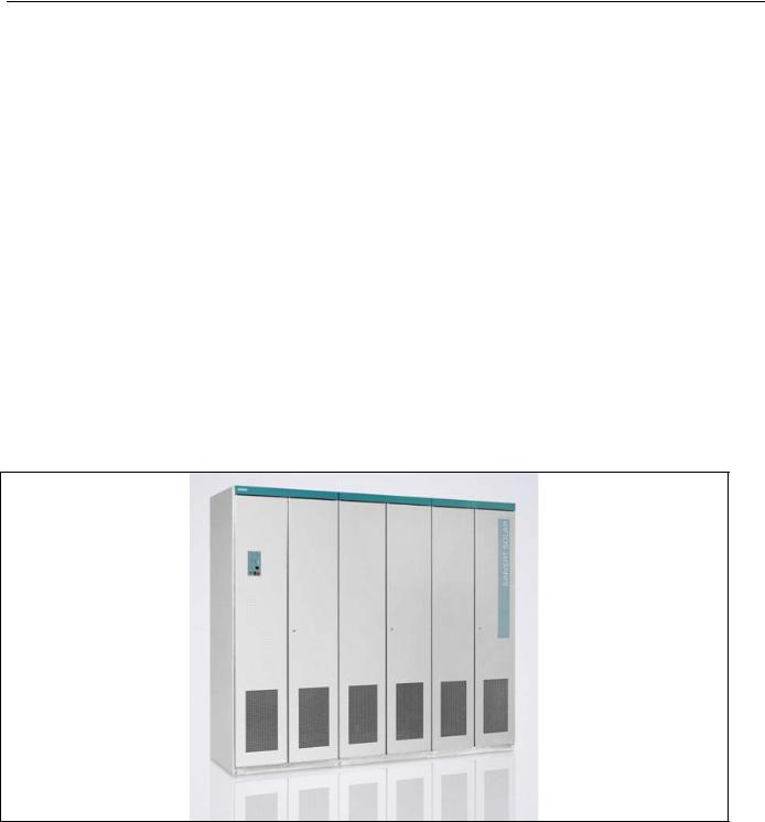
This system manual is valid for the following basic models of the SINVERT PV inverter:
•SINVERT 350 M
•SINVERT 420 M
•SINVERT 500 M TL
Figure 1-1 SINVERT 350/420/500 TL
6

Introduction
1.1 About this documentation
and their master-slave variants:
•SINVERT 700 MS (two SINVERT 350 inverters in parallel)
•SINVERT 1000 MS (three SINVERT 350 inverters in parallel)
•SINVERT 1400 MS (four SINVERT 350 inverters in parallel)
•SINVERT 850 MS (two SINVERT 420 inverters in parallel)
•SINVERT 1300 MS (three SINVERT 420 inverters in parallel)
•SINVERT 1700 MS (four SINVERT 420 inverters in parallel)
•SINVERT 1000 MS TL (two SINVERT 500 TL inverters in parallel)
•SINVERT 1500 MS TL (three SINVERT 500 TL inverters in parallel)
•SINVERT 2000 MS TL (four SINVERT 500 TL inverters in parallel)
1.1.2Target group
This documentation contains information of interest to the following target groups:
•Operators
•Service personnel
1.1.3Document structure
These installation and operating instructions are divided into five chapters:
Chapter |
Contents |
|
|
Introduction |
Information about the operating manual, overview of inverter types, |
|
target group |
Description |
Applications of SINVERT PV inverters |
|
|
Hardware operation |
Inverter operating guide |
|
|
Alarm and fault messages |
List of alarm and fault messages, causes and measures |
Support |
Contact details and information about support for SINVERT inverters |
|
and products by Siemens I IA S PV |
1.1.4History
Currently released editions of this manual:
Edition |
Remark |
11/2009 |
First edition |
7
Description
2.1 Application
2 Description
2.1Application
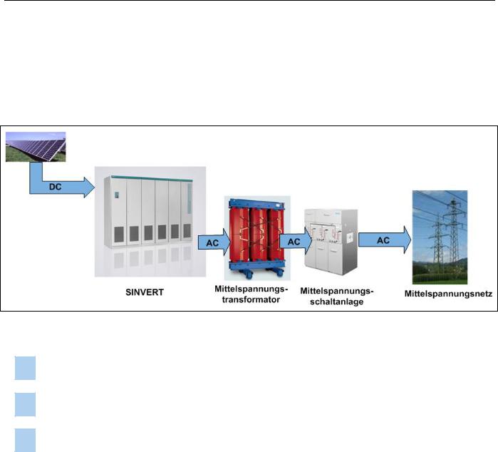
The SINVERT PV inverter is a fully assembled, ready-to-connect inverter unit for PV installations.
1 |
|
2 |
|
3 |
|
|
|
|
|
Figure 2-1 Overview of PV system
1The inverter transforms the DC voltage produced by the PV modules into an AC voltage.
2The AC output voltage is transformed to the grid voltage by a medium-voltage transformer.
3The PV solar system can thus be connected to the medium-voltage grid.
8

Hardware operation
3.1 Commissioning the inverter
3 Hardware operation
3.1Commissioning the inverter
Commissioning an installation requires certain switching operations to be performed. This type of work must always be undertaken by qualified, properly trained personnel. Failure to perform switching operations correctly can result in significant property damage and serious physical injury. The components described in this manual operate at hazardous voltages and currents. Proper precautions must be taken during the commissioning process. This manual describes only the manual process of switching the PV system on and off.
The system must be switched on and off manually in order to carry out performance tests and maintenance procedures.
CAUTION
The instructions and guidelines relating to operation and control of the installation contained in the operating manuals for the switching equipment and other devices described here must be adhered to.
3.1.1Instructions and safety information
In accordance with the relevant standards and legislation (e.g. DIN VDE 0105), properly trained specialists must always be employed to operate and control electrical equipment.
All employees authorized to undertake switching tasks must receive instruction in accordance with the relevant standards and legislation (in Germany, at least once annually in accordance with BGV A1 §4 (Institute for Statutory Accident Insurance and Prevention/Instruction of Insured Persons)).
Follow all safety guidelines and work instructions stipulated by the relevant legislation and standards. Never take any action which would endanger either yourself or others.
The five safety rules in Germany:
1.Isolate from power supply
2.Provide a safeguard to prevent unintentional reclosing
3.Make sure that the equipment is de-energized
4.Ground and short
5.Cover or place guards around adjacent live parts
CAUTION
The safety rules (for example, DIN VDE 0105 – 100 § 6.2 in Germany) are especially applicable to switching or voltage disconnection operations.
If you are working abroad, you must adhere to the relevant local safety rules. Always pay particular care and attention when working on or around electrical equipment.
9

Hardware operation
3.1 Commissioning the inverter
3.1.2Switching off and disconnecting the power supply
The entire system must be disconnected from the power supply before test and maintenance work can be carried out in the containers. Carry out these tasks in the sequence given below:
1.Press the OFF key briefly on the control panel of every inverter.
2.For reasons of safety, also press the Fast Stop button (if one is installed) in the inverter room.
3.Disconnect the external power supply (most commonly in the AC distribution cabinet) by opening the fuse switch disconnector or by switching off the miniature circuit breaker.
4.Open the AC-side and DC-side fuse switch disconnectors in all inverters and remove the fuses, including the fuse holder, or remove the fuse cartridge with a fuse tong. This means that the inverter cannot be switched on again (remember the five safety rules).
 DANGER
The AC and DC connections are still live externally!
5.In order to disconnect the AC end completely from the power supply, the relevant medium-voltage transformer must be switched off at the medium-voltage switchgear. After switching off, open the medium-voltage isolator and close the medium-voltage grounding switch. The machine switching operations on the medium-voltage components must be performed via the power supply company or an authorized person.
6.In order to disconnect the DC end completely from the power supply, all relevant junction boxes of the generator and coupling boxes (if installed) must be disconnected. The disconnectors in the generator junction boxes and/or coupling boxes (if installed) can be switched under load. In contrast, fuse switch disconnectors must not be switched under load. Likewise, fuse cartridges in fuse holders must not be removed under load.
 DANGER
Fuse switch disconnectors in the inverters and junction boxes must not be switched under load! Do not remove fuse cartridges when they are under load!
10
Hardware operation
3.1 Commissioning the inverter
3.1.3Switching on
The inverter is switched on in the same way as it is switched off, but in the reverse sequence.
1.Check that all connections have been made correctly (including polarity).
2.Switch on the junction boxes in the PV field.
3.Switch on the external power supply for the medium-voltage switchgear.
4.Switch on the external power supply for the inverter container.
5.Close the medium-voltage breaker. o Open the grounding switch.
o Close the switch disconnector. o Close the circuit breaker.
o Note: Depending on the type of MV switchgear installed, the step sequence might vary.
6.Close the DC fuse switch disconnectors in all inverters.
7.Close the AC fuse switch disconnectors in all inverters.
8.Unlock the "Fast Stop" button.
9.Turn the keyswitch on all inverters from "Auto" to "Test" and back to "Auto" in order to reset settings.
10.If insolation levels are sufficiently high, the system will restart automatically after 30 minutes.
11.To start the system immediately, you must turn the keyswitch on the master to the test position. Then press the internal key "S111".
12.The DC contactors are automatically closed one after the other. The inverter is then started and the AC contactor is immediately closed. Now turn the keyswitch to "Auto".
11
Hardware operation
3.2 Operating the inverter
3.2Operating the inverter
3.2.1Operator panel
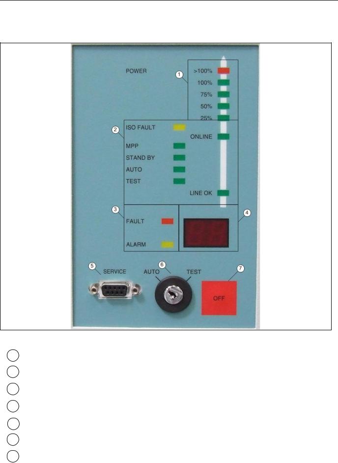
Figure 3-1 Front view of control panel
1 Grid LED indicator bar
2Status display
3Fault display
4Display
5 |
Service interface (RS 232) |
6 |
Keyswitch (operating mode) |
7 |
OFF key |
12
Hardware operation
3.2 Operating the inverter
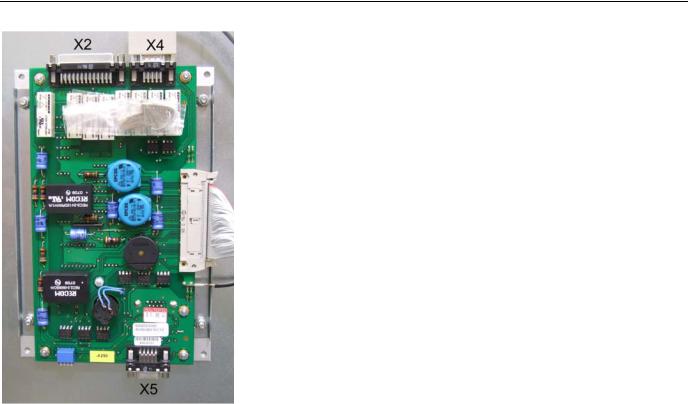
Figure 3-2 Front view of control panel
Table 3-1 Pin assignment X5 (SUB-D 9-pin/ RS422 for PPsolar)
Pin |
Signal |
1 |
RRS485P |
5 |
TRS485N |
6 |
TRS485P |
9 |
RRS485N |
13
 Loading...