


 Loading...
Instruction Manual  January 2007
sitrans
LR 460

Safety Guidelines: Warning notices must be observed to ensure personal safety as well as that of others, and to protect the product and the connected equipment. These warning notices are accompanied by a clarification of the level of caution to be observed.
Qualified Personnel: This device/system may only be set up and operated in conjunction with this manual. Qualified personnel are only authorized to install and operate this equipment in accordance with established safety practices and standards.
Unit Repair and Excluded Liability:
•The user is responsible for all changes and repairs made to the device by the user or the user’s agent.
•All new components are to be provided by Siemens Milltronics Process Instruments Inc.
•Restrict repair to faulty components only.
•Do not reuse faulty components.
Warning: This product can only function properly and safely if it is correctly transported, stored, installed, set up, operated, and maintained.
Note: Always use product in accordance with specifications.
Copyright Siemens Milltronics Process |
Disclaimer of Liability |
Instruments Inc. 2007. All Rights Reserved |
|
This document is available in bound version and in |
While we have verified the contents of this |
electronic version. We encourage users to purchase |
manual for agreement with the |
authorized bound manuals, or to view electronic versions |
instrumentation described, variations |
as designed and authored by Siemens Milltronics Process |
remain possible. Thus we cannot |
Instruments Inc. Siemens Milltronics Process Instruments |
guarantee full agreement. The contents of |
Inc. will not be responsible for the contents of partial or |
this manual are regularly reviewed and |
whole reproductions of either bound or electronic |
corrections are included in subsequent |
versions. |
editions. We welcome all suggestions for |
|
improvement. |
|
Technical data subject to change. |
MILLTRONICS®is a registered trademark of Siemens Milltronics Process Instruments Inc.
Contact SMPI Technical Publications at the following address:
Technical Publications
Siemens Milltronics Process Instruments Inc. 1954 Technology Drive, P.O. Box 4225 Peterborough, Ontario, Canada, K9J 7B1 Email: techpubs.smpi@siemens.com
•For a selection of Siemens Milltronics level measurement manuals, go to:
www.siemens.com/processautomation. Under Process Instrumentation, select Level Measurement and then go to the manual archive listed under the product family.
•For a selection of Siemens Milltronics weighing manuals, go to:
www.siemens.com/processautomation. Under Weighing Technology, select Continuous Weighing Systems and then go to the manual archive listed under the product family.
© Siemens Milltronics Process Instruments Inc. 2007

Table of Contents |
|
Safety Notes ............................................................................................................................................. |
1 |
Safety marking symbols .............................................................................................................. |
1 |
FCC and IC Conformity ........................................................................................................................... |
2 |
The Manual ............................................................................................................................................... |
3 |
Support ............................................................................................................................................ |
3 |
SITRANS LR 460 ................................................................................................................... |
5 |
Specifications ...................................................................................................................... |
6 |
Power............................................................................................................................................. |
6 |
Performance................................................................................................................................. |
6 |
Interface ........................................................................................................................................ |
7 |
Programmer (infrared keypad) ................................................................................................ |
8 |
Mechanical................................................................................................................................... |
8 |
Environmental .............................................................................................................................. |
9 |
Process.......................................................................................................................................... |
9 |
Communication............................................................................................................................ |
9 |
Approvals .................................................................................................................................... |
10 |
Dimensions........................................................................................................................................... |
11 |
Standard configuration ............................................................................................................. |
11 |
Installation ......................................................................................................................... |
12 |
Mounting Location ................................................................................................................................ |
12 |
Key considerations ...................................................................................................................... |
13 |
Nozzle design ............................................................................................................................. |
13 |
Nozzle location........................................................................................................................... |
13 |
Device orientation..................................................................................................................... |
13 |
Installation in vessel with obstructions ................................................................................. |
14 |
Easy Aimer Installation ........................................................................................................................ |
15 |
Air Purging System (Optional) ............................................................................................................ |
16 |
Universal Slotted Flange (for use with Air Purging Option only) ..................................... |
17 |
Optional Dust Cap ................................................................................................................................. |
18 |
Wiring .................................................................................................................................. |
19 |
Connecting SITRANS LR 460 .............................................................................................................. |
19 |
HART wiring .................................................................................................................................. |
20 |
PROFIBUS wiring ........................................................................................................................ |
21 |
Hazardous area installations ............................................................................................................. |
23 |
Product Nameplate ..................................................................................................................... |
23 |
Instructions specific to hazardous area installations ........................................................ |
23 |
Quick Start .......................................................................................................................... |
26 |
Activating SITRANS LR 460 ................................................................................................................ |
26 |
RUN mode display ....................................................................................................................... |
26 |
Programming SITRANS LR 460 .......................................................................................................... |
27 |
The handheld programmer and PROGRAM mode display ............................................... |
27 |
i |
|
Contents of Table

Table of Cotents
Quick Start Wizard via the handheld programmer |
.............................................................28 |
Quick Start Wizard via SIMATIC PDM ................................................................................... |
30 |
Device Description (DD) .......................................................................................................... |
30 |
Quick Start Wizard steps......................................................................................................... |
31 |
Level application example ................................................................................................................... |
34 |
Auto False Echo Suppression ............................................................................................................ |
35 |
Operating SITRANS LR 460 via SIMATIC PDM ............................................................ |
36 |
Functions in SIMATIC PDM ................................................................................................................ |
36 |
SIMATIC PDM Rev. 6.0, SP2 Features .................................................................................... |
36 |
Echo profile saving and viewing............................................................................................ |
37 |
Trend Diagram (Level Trend over Time) ............................................................................. |
37 |
Manual TVT Shaper.................................................................................................................. |
38 |
Accessing Functions in PDM ................................................................................................... |
39 |
Changing parameter settings via SIMATIC PDM ............................................................... |
40 |
Configuring a new device ......................................................................................................... |
40 |
Calibrating LR 460 via PDM ....................................................................................................... |
41 |
Parameters accessed via pull-down menus ........................................................................ |
41 |
Reset ............................................................................................................................................ |
41 |
Configuration Flag Reset (HART only).................................................................................. |
41 |
Auto False Echo Suppression ................................................................................................ |
41 |
D/A (Digital/Analog) Trim ........................................................................................................ |
42 |
Simulate AO (Analog Output) ................................................................................................. |
42 |
Simulation ................................................................................................................................... |
42 |
Parameter Reference ....................................................................................................... |
43 |
Parameter menus ........................................................................................................................ |
43 |
Pull-down menus via SIMATIC PDM ..................................................................................... |
43 |
Quick Start Wizard ................................................................................................................................ |
44 |
Quick Start ............................................................................................................................................. |
44 |
Language ..................................................................................................................................... |
44 |
Application Type ....................................................................................................................... |
44 |
Operation .................................................................................................................................... |
44 |
Units.............................................................................................................................................. |
45 |
High Calibration Point .............................................................................................................. |
45 |
Low Calibration Point ............................................................................................................... |
45 |
Rate............................................................................................................................................... |
45 |
Apply Changes........................................................................................................................... |
45 |
Identification ........................................................................................................................................ |
46 |
Operation Unit ............................................................................................................................ |
46 |
Configuration .............................................................................................................................. |
46 |
Device .......................................................................................................................................... |
48 |
Statistics...................................................................................................................................... |
49 |
Input ....................................................................................................................................................... |
50 |
Static Revision Number ........................................................................................................... |
50 |
Class ............................................................................................................................................. |
50 |
Standard Setup .......................................................................................................................... |
50 |
Sensor Calibration .................................................................................................................... |
51 |
Measuring Limits....................................................................................................................... |
53 |
Detailed Setup ........................................................................................................................... |
53 |
ii |
|

Echo Information ....................................................................................................................... |
61 |
Output .................................................................................................................................................... |
61 |
AIFB1............................................................................................................................................ |
61 |
AIFB2............................................................................................................................................ |
65 |
mA Output ................................................................................................................................... |
65 |
Relay Configuration .................................................................................................................. |
67 |
Device Certification .................................................................................................................. |
67 |
Remaining Device Lifetime ..................................................................................................... |
68 |
Remaining Sensor Lifetime..................................................................................................... |
68 |
Service Interval.......................................................................................................................... |
69 |
Calibration Interval.................................................................................................................... |
69 |
Appendix A: Technical Reference ................................................................................. |
71 |
Principles of Operation ........................................................................................................................ |
71 |
Measurement Response ..................................................................................................................... |
71 |
Echo Processing ................................................................................................................................... |
72 |
Profile monitoring via SIMATIC PDM ..................................................................................... |
72 |
Time Varying Threshold (TVT)................................................................................................ |
72 |
Echo selection .............................................................................................................................. |
72 |
False Echoes ........................................................................................................................................... |
73 |
Auto False-Echo Suppression .................................................................................................. |
73 |
Near Range (Blanking) .............................................................................................................. |
74 |
Echo confidence .................................................................................................................................... |
74 |
Loss of Echo (LOE) ....................................................................................................................... |
74 |
LOE Timer .................................................................................................................................... |
74 |
Fail-safe Mode ....................................................................................................................................... |
74 |
Maximum Process Temperature Chart ............................................................................................ |
76 |
Appendix B: Troubleshooting ......................................................................................... |
77 |
General Fault Codes/PROFIBUS PA Extended Diagnostics ...................................................... |
80 |
Appendix C: Maintenance .............................................................................................. |
84 |
Unit Repair and Excluded Liability .................................................................................................... |
84 |
Appendix D: Local Operation Interface ........................................................................ |
85 |
The LCD Display ..................................................................................................................................... |
85 |
RUN mode (startup display) ..................................................................................................... |
85 |
PROGRAM Mode Display ......................................................................................................... |
85 |
The handheld programmer ................................................................................................................. |
86 |
Hand-held programmer: key functions in RUN mode ........................................................ |
86 |
PROGRAMMING via the handheld programmer ................................................................ |
86 |
Hand-held programmer: key functions in Navigation mode .......................................... |
87 |
Hand-held programmer: key functions in Edit mode........................................................ |
87 |
Individual Parameter Reset .................................................................................................... |
87 |
Appendix E: HART Communications ............................................................................ |
88 |
HART Device Description (DD) ........................................................................................................... |
88 |
SIMATIC Process Device Manager (PDM) ..................................................................................... |
88 |
HART modem interface for SIMATIC PDM .......................................................................... |
88 |
HART Version ......................................................................................................................................... |
89 |
iii |
|
Contents of Table

Table of Cotents
Burst Mode ................................................................................................................................... |
89 |
HART Communication Parameter ..................................................................................................... |
89 |
Appendix F: HART Information Structure ..................................................................... |
90 |
Block Model for recording and processing measured values ................................................... |
90 |
Description of the blocks ........................................................................................................... |
91 |
Appendix G: Remote operation via PROFIBUS PA ..................................................... |
92 |
Configuration tool .................................................................................................................................. |
92 |
SIMATIC PDM .............................................................................................................................. |
92 |
Device Description.................................................................................................................... |
92 |
Configuration ................................................................................................................................ |
93 |
The GSD file................................................................................................................................ |
93 |
Setting the PROFIBUS address.............................................................................................. |
93 |
Configuring a new device: procedure.................................................................................. |
93 |
Configuring PROFIBUS PA with an S7-300/ 400 PLC ........................................................ |
94 |
Calibration via SIMATIC PDM .................................................................................................. |
94 |
Appendix H: Communication via PROFIBUS PA ......................................................... |
95 |
Cyclic versus Acyclic Data .................................................................................................................. |
95 |
Cyclic Data .................................................................................................................................... |
95 |
Status Byte ............................................................................................................................................. |
96 |
Diagnostics ............................................................................................................................................. |
97 |
Diagnosis reply (applies only to cyclic masters) ................................................................. |
97 |
Acyclic Diagnostics ..................................................................................................................... |
97 |
Acyclic Extended Diagnostics (General Fault Codes) ........................................................ |
98 |
Acyclic Data Transmission .................................................................................................................. |
98 |
Appendix J: PROFIBUS PA Profile Structure ............................................................... |
99 |
PROFIBUS Level Device Design ........................................................................................................ |
99 |
Block Model for recording and processing measured values ...................................... |
99 |
Description of the blocks ........................................................................................................ |
100 |
Level Transducer Block function groups ......................................................................... |
100 |
Analog Input Function Blocks 1 and 2............................................................................... |
102 |
Appendix K: Software Revision History ..................................................................... |
105 |
Glossary ............................................................................................................................ |
107 |
Index .................................................................................................................................. |
111 |
LCD menu structure ........................................................................................................ |
113 |
iv

Safety Notes
Special attention must be paid to warnings and notes highlighted from the rest of the text by grey boxes.
WARNING: relates to a caution symbol on the product, and means
that failure to observe the necessary precautions can result in death, serious injury, and/or considerable material damage.
WARNING: means that failure to observe the necessary precautions can result in death, serious injury, and/or considerable material
damage.
Note: means important information about the product or that part of the operating manual.
Safety marking symbols
In manual: |
On product: |
Description |
|||
|
|
|
|
|
|
|
|
|
|
|
Earth (ground) Terminal |
|
|
|
|
|
|
|
|
|
|
|
|
|
|
|
|
|
|
|
|
|
|
|
Protective Conductor Terminal |
|
|
|
|
|
|
|
|
|
|
|
|
|
|
|
|
|
|
|
|
|
|
|
Alternating Current |
|
|
|
|
|
|
|
|
|
|
|
Direct Current |
|
|
|
|
|
|
|
|
|
|
|
|
|
|
|
|
|
(Label on product: yellow background.) WARNING: refer |
|
|
|
|
|
|
|
|
|
|
|
to accompanying documents (manual) for details. |
|
|
|
|
|
|
460 LR SITRANS
7ML19985JM01 |
SITRANS LR 460 – INSTRUCTION MANUAL |
Page 1 |

FCC and IC Conformity
US Installations only: Federal Communications Commission (FCC) rules
WARNING: Changes or modifications not expressly approved by Siemens Milltronics could void the user’s authority to operate the equipment.
Notes:
|
• This equipment has been tested and found to comply with the limits for a Class A |
|
|
digital device, pursuant to Part 15 of the FCC Rules. These limits are designed to |
|
460 |
provide reasonable protection against harmful interference when the equipment is |
|
operated in a commercial environment. |
||
• This equipment generates, uses, and can radiate radio frequency energy and, if not |
||
LR |
||
installed and used in accordance with the instruction manual, may cause harmful |
||
SITRANS |
||
interference to radio communications. Operation of this equipment in a residential |
||
|
||
|
area is likely to cause harmful interference to radio communications, in which case |
|
|
the user will be required to correct the interference at his own expense. |
|
|
Canadian Installations only: Industry Canada (IC) rules |
|
|
|
Notes:
•This device shall be installed and operated in a completely enclosed container to prevent RF emission, which otherwise can interfere with aeronautical navigation. Installation shall be done by trained installers, in strict compliance with the manufacturer’s instructions.
•The use of this device is on a ’no-protection non-interference’ basis.
-The user shall accept operations of high powered radar in the same frequency band, which may interfere with or damage this device.
-The user is responsible for removing, at the user’s expense, any device found to interfere with primary licensing operations.
Page 2 |
SITRANS LR 460 – INSTRUCTION MANUAL |
7ML19985JM01 |

The Manual
Note: Please follow the installation and operating procedures for a quick, trouble-free installation and to ensure the maximum accuracy and reliability of your SITRANS
LR 460. This manual applies to the SITRANS LR 460 only.
This manual will help you set up your SITRANS LR 460 for optimum performance. We always welcome suggestions and comments about manual content, design, and accessibility. Please direct your comments to techpubs.smpi@siemens.com.
For other Siemens Milltronics level measurement manuals, go to: www.siemens.com/level, and look under Level Measurement.
Application Examples
The application example used in this manual illustrates a typical installation using SITRANS LR 460. There is often more than one way to approach an application, and other configurations may also apply. If the example does not apply to your application, check the applicable parameter reference for the available options.
Support
If you have questions, you can access our 24-hour hotline at: www.siemens.com/automation/support-request
Phone: +49 180 50 50 222
Abbreviations and Identifications
Short |
Long Form |
Description |
Units |
|
form |
||||
|
|
|
||
|
|
|
|
|
A/D |
Analog to digital |
|
|
|
|
|
|
|
|
AIFB |
Analog Input Function Block |
|
|
|
CE / FM / |
Conformitè Europèene / |
|
|
|
Factory Mutual / Canadian |
safety approval |
|
||
CSA |
|
|||
Standards Association |
|
|
||
|
|
|
||
|
|
|
|
|
Ci |
Internal capacitance |
|
|
|
D/A |
Digital to analog |
|
|
|
|
|
|
|
|
DAC |
Digital Analog Converter |
|
|
|
DCS |
Distributed Control System |
control room apparatus |
|
|
|
|
|
|
460 LR SITRANS
7ML19985JM01 |
SITRANS LR 460 – INSTRUCTION MANUAL |
Page 3 |

SITRANS LR 460
Short |
Long Form |
Description |
Units |
|
form |
(cont’d) |
|||
|
|
|||
|
|
|
|
|
FV |
Full Vacuum |
|
|
|
|
|
|
|
ESD |
Electrostatic Discharge |
|
HART PV |
HART Primary Variable |
|
HART SV |
HART Secondary Variable |
|
Ii |
Input current |
|
Io |
Output current |
|
IS |
Intrinsically Safe |
|
Li |
Internal inductance |
|
LR |
Level Radar |
|
LTB |
Level Transducer Block |
|
mH |
milliHenry |
|
F |
microFarad |
|
s |
microsecond |
|
PA |
Process Automation |
|
(PROFIBUS) |
||
|
||
PDM |
Process Device Manager |
|
(SIMATIC) |
||
|
||
pF |
pico Farads |
|
ppm |
parts per million |
|
psia |
pounds/square inch absolute |
|
PV |
Primary Value1 |
|
RH |
relative humidity |
|
SCFM |
standard cubic feet/minute |
|
SV1 |
Secondary Value1 1 |
|
SV2 |
Secondary Value2 1 |
|
TV |
Transmitter Variable |
|
TVT |
Time Varying Threshold |
|
Ui |
Input voltage |
|
Uo |
Output voltage |
Output value from AIFB1
Output value from AIFB2
|
mA |
|
mA |
safety approval |
|
|
mH |
10-3 |
Henry |
10-6 |
Farad |
10-6 |
Second |
10-12 |
Farad |
default measured value
LTB level output (level units)
LTB distance output (sensor units)
sensitivity threshold
V
V
1.The output from the Level Transducer Block can be called the Primary Value (or Secondary Value). When it becomes the input to the AIFB, it is called the Process Variable. It is distinct from the HART PV.
Page 4 |
SITRANS LR 460 – INSTRUCTION MANUAL |
7ML19985JM01 |
SITRANS LR 460
SITRANS LR 460 is a 4-wire 24 GHz FMCW (Frequency Modulated/Continuous Wave) radar level transmitter with advanced signal processing for continuous monitoring of solids up to 100 meters. It is ideal for extreme dust and difficult applications. The Easy Aimer design makes it easy to install the device and orient the signal towards the material angle of repose. The high frequency signal creates a narrow emission cone, which makes the LR 460 quite insensitive to vessel interferences.
460 LR SITRANS
SITRANS LR 460 is available with an optional air purge connection for cleaning the interior of the antenna.
Programming
SITRANS LR 460 carries out its level measurement function according to the set of built-in parameter tables. You can make parameter changes via the Siemens Milltronics handheld programmer, a PC running SIMATIC PDM or a HART handheld communicator.
Approvals and Certificates
SITRANS LR 460 is available with General Purpose approval, or approval for hazardous areas containing dust. For details see Approvals on page 10.
System Implementation
SITRANS LR 460 supports HART communication protocol, or PROFIBUS PA (optional), and SIMATIC PDM software.
7ML19985JM01 |
SITRANS LR 460 – INSTRUCTION MANUAL |
Page 5 |

Specifications
Specifications
Note: Siemens Milltronics makes every attempt to ensure the accuracy of these specifications, but reserves the right to change them at any time.
SITRANS LR 460
Power
Power Supply
•100 to 230 V AC, ±15%, 50/60 Hz, 6 W
•24 V DC, +25/-20%, 6 W
• |
Fuse (AC) |
SI1 |
Fast acting ceramic, 4 x 20 mm, 1 A, 250 V AC |
|
|
SI2 |
Slow-Blow, 4 x 20 mm, 0.63 A, 250 V AC |
• |
Fuse (DC) |
SI1 |
Fast acting ceramic, 4 x 20 mm, 2 A, 250 V AC |
|
|
SI2 |
Slow-Blow, 4 x 20 mm, 0.63 A, 250 V AC |
Performance
Reference operating conditions according to IEC 60770-1
• |
ambient temperature |
+15 to +25 oC |
• |
humidity |
45 to 75% relative humidity |
• |
ambient pressure |
860 to 1060 mbar (12.47 to 15.37 psi) |
Measurement Accuracy (measured in accordance with IEC 60770-1) |
||
• |
non-linearity (accuracy) |
greater of 25 mm (1”) or 0.25% of span (including |
|
|
hysteresis and non-repeatability) |
• |
non-repeatability |
10 mm (0.4”) [included in non-linearity specification] |
• |
deadband (resolution) |
10 mm (0.4”) [included in non-linearity specification] |
• |
hysteresis error |
0 mm |
Analog Output Accuracy (measured in accordance with IEC 60770-1) |
||
• |
non-linearity (accuracy) |
0.100% of span (including hysteresis and repeatability) |
• |
non-repeatability |
0.030% of span (included in non-linearity specification) |
• |
deadband (resolution) |
0.030% of span [included in non-linearity specification] |
• |
hysteresis error |
0% |
Frequency |
25 GHz nominal |
|
Measurement range1 |
0.35 to 100 m (1.15 to 328.08 ft). |
|
1. Referenced from flange face.
Page 6 |
SITRANS LR 460 – INSTRUCTION MANUAL |
7ML19985JM01 |

Long-term stability |
≤ ± 1 mm/year |
|
Near Range (blanking) |
0.35 m (1.15 ft) |
|
Update time |
mA output and loop display is updated once per |
|
|
|
second |
Beam angle |
|
|
• |
3" horn: |
11° at –3 dB boundary |
• |
4" horn: |
8° at –3 dB boundary |
Memory
•non-volatile EEPROM
•no battery required
Interface
Analog output (Not applicable to PROFIBUS PA option)
• |
signal range |
4 to 20 mA |
|
|
upper limit 20 to 23 mA adjustable |
• |
fail signal |
3.6 mA to 23 mA; or last value |
• |
load |
Max. 600 Ω; for HART1 communication min. 230 Ω |
Digital output |
|
|
• |
function |
Configurable as a device status or limit value (level) |
• |
signal type |
Relay, either NCC or NOC function, max. 50 V DC, |
|
|
max. 200 mA, rating max. 5 W. |
|
|
Self-resetting fuse, Ri = 9 Ω |
Electrical isolation |
Outputs electrically isolated from the power supply and |
|
|
|
from each other |
Display |
|
|
• |
LCD |
two lines of 16 characters each, configurable for the |
|
|
following displays: |
|
|
level, amplitude, digital output, |
|
|
temperature, validity, signal-to-noise ratio, |
|
|
output current, distance |
Specifications
1. HART® is a registered trademark of HART Communication Foundation.
7ML19985JM01 |
SITRANS LR 460 – INSTRUCTION MANUAL |
Page 7 |

Programmer (infrared keypad)1
Siemens Milltronics infrared IS (Intrinsically Safe) handheld programmer for hazardous and all other locations (battery is non-replaceable)
• |
approval: |
ATEX II 1 G EEx ia IIC T4, certificate SIRA 01ATEX2147 |
|
|
CSA and FM Class I, Div. 1, Gr. A, B, C, D T6 @ max. |
|
|
ambient temperature of 40 °C (104 °F) |
• |
ambient temperature: |
−20 to 40 °C (−5 to 104 °F) |
• |
interface: |
proprietary infrared pulse signal |
• |
power: |
3 V lithium battery |
• |
weight: |
150 g (0.3 lb) |
• |
color: |
black |
Mechanical
|
Wetted parts (in contact |
|
|||
|
with the process) |
|
|
|
|
|
• |
flange and horn |
304 stainless steel (or equivalent) |
|
|
|
• |
emitter |
PTFE |
|
|
|
Process Connection |
|
|
|
|
|
• |
universal flanges |
3"/80 mm, 4"/100 mm, 6"/150 mm (See page 17 for flange |
||
|
|
|
dimensions.) |
|
|
|
Pressure (vessel) |
0.5 bar (7.25 psi) maximum |
|
||
|
Horn |
|
|
|
|
|
• |
3" horn |
2.93" (74.5 mm) diameter |
|
|
|
• |
4" horn |
3.84" (97.5 mm) diameter |
|
|
|
Weight |
|
|
|
|
|
• |
Weight of instrument and flange |
|
||
|
|
|
|
|
|
|
|
|
Process Connection |
|
Weight |
Specifications |
|
Universal, 3" / 80 mm flange with 3" horn |
|
6.1 kg (13.4 lbs) |
|
|
|
|
|
|
|
|
|
Universal, 4" / 100 mm flange with 4" horn |
|
10.6 kg (23.36 lbs) |
|
|
|
|
|
|
|
|
|
Universal, 6" / 160 mm flange with 4"horn |
|
TBA |
|
|
|
|
|
|
|
|
|
|
|
|
|
1.Ordered separately.
Page 8 |
SITRANS LR 460 – INSTRUCTION MANUAL |
7ML19985JM01 |

Enclosure |
|
|
• |
construction |
Die-cast aluminum, painted (polyester powder-coated) |
• |
conduit |
2 x M20 |
|
|
or 2 x ½” NPT (option) |
• |
ingress protection |
Type 4X/NEMA 4X, Type 6/NEMA 6, IP671 |
Dust cap (optional) |
|
|
• |
3" |
PTFE, pipe clamp connection, O.D. 95 mm (3.74") |
• |
4" |
PTFE, pipe clamp connection, O.D. 120 mm (4.72") |
Air Purge Connection |
|
|
• |
equipped with female 1/8" NPT fitting |
|
Environmental
• |
location |
indoor/outdoor |
• |
altitude |
2000 m (6562 ft) max |
• |
relative humidity |
suitable for outdoor (Type / NEMA 4X, 6/ IP67) |
• |
installation category |
II |
• |
pollution degree |
4 |
• |
permitted ambient |
-40 to 65 °C (-40 to 149 °F) (non-hazardous version) |
|
|
temperature3LCD: -10 to 55 °C (14 to 131 °F) |
|
|
Observe the temperature classes in hazardous areas! |
Process
• |
Process temperature2 |
-40 to 200 °C (-40 to 392 °F) |
• |
Pressure (vessel) |
0.5 bar (7.25 psi) maximum |
Communication
Communication: HART |
230 to 600 Ω, 230 to 500 Ω when connecting a coupling |
|
• |
Load |
|
|
|
module |
• |
Max. Line Length |
multi-wire: ≤ 1500 m (4921 ft) |
• |
Protocol |
HART, Version 5.1 |
Specifications
1.Use only approved, suitable sized hubs for watertight applications.
2.Process temperature varies with ambient temperature. See Process/Ambient de-rating curves in Appendix III.
7ML19985JM01 |
SITRANS LR 460 – INSTRUCTION MANUAL |
Page 9 |

Communication: PROFIBUS PA |
|
|
• Protocol |
PROFIBUS PA, |
|
|
|
technology: IEC 61158-2, slave-functionality |
• |
Device Class |
B |
• |
Device Profile |
3.01 |
Bus current (PROFIBUS PA) |
10.5 mA |
|
Approvals
• |
Hazardous areas |
FM/CSA Class II, Div. 1, Groups E,F and G, Class III |
|
|
ATEX II 1 D; 1/2 D, 2D T85 deg C |
• General |
CSAus/c, FM, CE |
|
• |
Radio |
FCC, Industry Canada, European Radio (R&TTE) |
Specifications
Page 10 |
SITRANS LR 460 – INSTRUCTION MANUAL |
7ML19985JM01 |
Dimensions
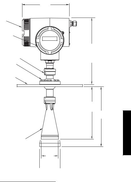
Standard configuration
connection cover
electronics cover
purge connection
Easy Aimer ball locking bolts
universal slotted flange (see page 17 for details)
horn antenna
204 mm (8.0")
287 mm (11.29")
reference point
228 mm (8.97")
285 mm (11.22")
74.5 mm |
3" horn |
(2.93") |
97.5 mm
 (3.84")
  4" horn
1.Consult factory when using horn extension in applications subject to shock and vibration.
2.Universal flange mates with EN 1092-1 / ASME B16.5 / JIS B2238 bolt hole pattern.
Specifications
7ML19985JM01 |
SITRANS LR 460 – INSTRUCTION MANUAL |
Page 11 |

Installation
WARNINGS:
•SITRANS LR 460 is to be used only in the manner outlined in this manual, otherwise protection provided by the equipment may be impaired.
•Installation shall only be performed by qualified personnel and in accordance with local governing regulations.
Notes:
•For European Union and member countries, installation must be according to ETSI EN 302372.
•Refer to device nameplate for approval information.
•Use appropriate conduit and conduit fittings or cable glands, to maintain IP or NEMA rating.
•Observe all maximum permissible ambient and process temperatures. Refer to
Maximum Process Temperature Chart on page 76.
•For US and Canadian installations, see FCC and IC Conformity on page 2.
Mounting Location
Notes:
•Provide easy access for viewing the display and programming via the handheld programmer.
•Provide an environment suitable to the housing rating and materials of construction.
•Provide a sun shield if the device is mounted in direct sunlight.
ambient temperature max. 65 °C (149 °F)-
flange temperature
process temperature max. 200 °C (392 °F)
Installation
Page 12 |
SITRANS LR 460 – INSTRUCTION MANUAL |
7ML19985JM01 |
Key considerations
•Correct location is critical to a successful application.
•Avoid reflective interference from vessel walls and obstructions by following the guidelines below.
Nozzle design
•Bottom edge of horn must project from nozzle.
•Nozzle must allow adequate
clearance to allow positioning if LR
460 has to be at an angle so that emission cone perpendicular to
material surface.
Min. clearance: 10 mm (0.4")
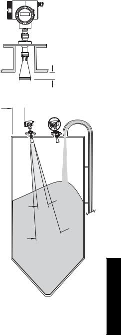
Nozzle location
•Locate antenna at least 1 meter away from side wall.
•Keep emission cone free of interference from ladders, pipes, I-beams or filling streams.
•Make allowance for beam spread to avoid interference with the emission cone.
Device orientation
•Align the antenna so that the radar cone is perpendicular to the surface of the monitored material, if possible. (See Easy Aimer Installation on page 15.)
•To compensate for vessels with obstructions, see also Polarization Reference Point on page 14.
 min. 1 m (39")
emission cone
4" horn
8° 
3" 11°  horn
horn
Installation
7ML19985JM01 |
SITRANS LR 460 – INSTRUCTION MANUAL |
Page 13 |
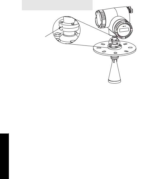
Installation in vessel with obstructions
Polarization Reference Point
Obstructions such as ladders, pipes, or the fill path, can cause false reflections. To avoid this, use the Polarization Reference Point to orient the device.
•A small center punch mark provides a polarization reference point.
•To get the best signal, rotate the device till the Polarization Reference Point either faces towards the obstruction, or faces away from the obstruction (at 180 degrees).
Note: the device can be rotated through 360 degrees without damage to the unit.
Polarization
Reference
Point
Installation
Page 14 |
SITRANS LR 460 – INSTRUCTION MANUAL |
7ML19985JM01 |
Easy Aimer Installation
Note: When the Easy Aimer ball is loosened, the device is free to tilt to a maximum of 30°.
0.38" (10 mm)
285 mm (11.22")
Easy Aimer ball locking bolts
top clamping plate (upper socket)
bottom clamping plate (lower socket)
customer gasket as required [recommended thickness 1.5 to 1.8 mm (0.06 to 0.07")]
customer mounting plate, as required
ø 4" (102 mm) min., central opening
30°
 max.
max.
1.Holding the electronics enclosure firmly, loosen the Easy Aimer ball locking bolts and gently reposition the enclosure.
2.Direct SITRANS LR 460 so the horn antenna is pointed at an angle perpendicular to the material surface, if possible. (As a guide, aim the beam at a point approximately 2/3 of the way across the tank diameter.)
3.When the desired position is reached, retighten the 5 bolts to 15-23 N m (11 to 17 Lbf-ft).
Easy Aimer
Installation
7ML19985JM01 |
SITRANS LR 460 – INSTRUCTION MANUAL |
Page 15 |
Air Purging System (Optional)
For more frequent cleaning, a purging system can be installed between the flange and the horn antenna. The system provides an 1/8" inlet (female thread) on the flange where cooling air or cleaning fluid passes through the flange and exits the inside of the horn to clean it. The customer will supply the purging medium by a manual or automatic valve system.
This option is only available with the universal flange for purging shown on page 17.
Notes:
•The Air Purge feature should not be activated with a dust cap in place.
•Purge duration, pressure, and interval, will vary with each application. It is the user’s responsibility to determine the requirements depending on the application and cleaning required.
•Short duration bursts of high pressure provide more effective cleaning than continuous low pressure air.
•Some dust particles are highly abrasive and can be drawn into the inside of the horn during purge cleaning, damaging the internal PTFE emitter of the antenna. A replacement kit is available from your local Siemens Milltronics representative.
•It is the customer’s responsibility to ensure that any vacuum or pressure in the measured vessel is maintained, considering the hole that passes through the process connection and SITRANS LR 460 antenna system.
|
Recommendation for |
|
Air Consumption |
|
effective cleaning |
(Flow rate versus applied pressure) |
|
|
|
Air Pressure |
Approx. inlet volume flow rate |
|
Pressure: 90 to 110 psi |
20 |
5 SCFM |
|
|
40 |
6 SCFM |
|
Inlet flow: 10 SCFM 1 |
60 |
8 SCFM |
|
80 |
9 SCFM |
|
|
|
90 |
10 SCFM |
• |
The purge connection is closed |
|
|
|
by the manufacturer, using a 1/8" |
|
|
|
plug. |
|
|
• |
When the plug is removed to |
|
|
|
connect a purging system, the |
|
|
|
operator is responsible for |
|
|
|
ensuring that the purging circuit |
|
|
|
conforms to "Ex" requirements: |
|
|
|
for example, by fitting an NRV |
purged process |
|
|
valve. |
||
|
|
connection with factory- |
|
installed 1/8" NPT plug
Installation
1.SCFM (standard cubic feet/minute) referenced to 14.7 psia, 68°F and 36% relative humidity (RH).
Page 16 |
SITRANS LR 460 – INSTRUCTION MANUAL |
7ML19985JM01 |
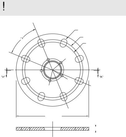
Universal Slotted Flange (for use with Air Purging Option only)
WARNING: The user is responsible for the selection of bolting and gasket materials which will fall within the limits of the flange and its intended use and which are suitable for the service conditions.
number of slotted bolt holes
bolt hole circle max. diameter
bolt hole circle min. diameter
flange O.D.
|
|
|
|
|
|
|
|
|
|
|
|
|
|
|
|
|
|
|
|
|
|
|
|
|
|
|
|
|
|
|
|
|
|
|
|
|
|
|
|
|
|
|
|
|
|
|
|
|
|
|
|
|
|
|
|
|
thickness |
|
|
|
|
|
|
|
|
|
|
|
|
|
|
|
|
|
|
|
|
|
|
|
|||
|
|
|
|
|
|
|
|
|
|
|
|
|
|
|
|
|
|
|
|
|
|
|
|
|
|
|
|
|
|
|
|
|
|
|
|
|
|
|
|
|
|
|
|
|
|
|
|
|
|
|
|
|
|
|
|
|
|
|
|
|
||
|
|
|
|
|
|
|
section A-A |
|
|
|
|
|
|
|
|
|
|
|
|
|
|
Slotted Flange Dimensions (see above) |
|
|
|
|
|
|
|
|
|
|
|
|
|||||||
|
|
|
|
|
|
|
|
|
|
|
|
|
|
|
|
|
|
|
|
|
|
Pipe |
|
Flange |
Thick- |
Bolt Hole |
Bolt Hole |
|
Bolt Hole |
No. of |
|
|
|||||||||
|
|
|
Slotted |
|
|
|||||||||||||||
|
Size |
|
O.D. |
ness (s) |
Circle Max Ø |
Circle Min Ø |
|
|
radius |
|
|
|||||||||
|
|
|
|
Holes |
|
|
||||||||||||||
|
|
|
|
|
|
|
|
|
|
|
|
|
|
|
|
|
|
|
||
|
|
|
|
|
|
|
|
|
|
|
|
|
|
|
|
|
|
|
|
|
|
3" or |
|
7.87" |
|
0.38" |
|
6.30" |
|
5.91" |
|
0.38" |
|
8 |
|
|
|
||||
|
80 mm |
|
(200 mm) |
(9.65 mm) |
(160 mm) |
(150 mm) |
|
(9.5 mm) |
|
|
|
|
||||||||
|
|
|
|
|||||||||||||||||
|
|
|
|
|
|
|
|
|
|
|
|
|
|
|
|
|
|
|
|
|
|
4" or |
|
9.00" |
|
0.38" |
|
7.52" |
|
6.89" |
|
0.38" |
|
8 |
|
|
|
||||
|
100 mm |
|
(229 mm) |
(9.65 mm) |
(191 mm) |
(175 mm) |
|
(9.5 mm) |
|
|
|
|
||||||||
|
|
|
|
|
|
|
|
|
|
|
|
|
|
|
|
|
|
|
|
|
|
6" or |
|
11.22" |
|
0.38" |
|
9.53" |
|
9.45" |
|
0.45" |
|
8 |
|
|
Installation |
||||
|
150 mm |
|
(285 mm) |
(9.65 mm) |
(242 mm) |
(240 mm) |
|
(11.5 mm) |
|
|
|
|||||||||
|
|
|
|
|
|
|
||||||||||||||
|
|
|
|
|
|
|
|
|
|
|
|
|
|
|
|
|
|
|
|
|
|
|
|
|
|
|
|
|
|
|
|
|
|
|
|
|
|
|
|
|
|
7ML19985JM01 |
|
|
SITRANS LR 460 – INSTRUCTION MANUAL |
|
|
|
|
|
Page 17 |
|
||||||||||
|
|
|
|
|
|
|
|
|||||||||||||
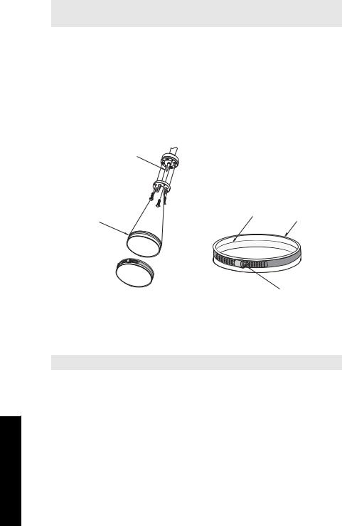
Optional Dust Cap
Note: The dust cap must be removed before using the Air Purge feature (see Air Purging System (Optional) on page 16).
The dust cap fits onto the end of the horn and prevents the buildup of dust and other process material inside the horn.
•It is particularly useful for applications in areas of high humidity, or with bulk solids with a high moisture content.
•Two sizes are available, to fit the standard 3" and 4" horns.
Installation
1.Thoroughly clean inside the horn. If you remove the horn for easier cleaning, take care not to damage or bend the plastic emitter.
plastic emitter
groove |
ridge |
dust cap |
|
clamp screw
2.Press the cap firmly onto the horn until the ridge inside the cap snaps into position in the groove on the outside of the horn.
3.Hand tighten the adjustable clamp supplied to secure the cap.
4.Use a screwdriver or nut driver to tighten the clamp screw until the clamp provides an air-tight seal.
Note: It is critical to ensure no moisture can be trapped inside.
Installation
Page 18 |
SITRANS LR 460 – INSTRUCTION MANUAL |
7ML19985JM01 |

Wiring
WARNINGS:
•Turn off power to the device before unscrewing the housing cover in a hazardous area.
•All field wiring for AC models must have insulation suitable for at least 250 V.
•The DC input terminals shall be supplied from a source that provides electrical isolation between the input and the output, in order to meet the applicable safety requirements of IEC 61010-1.
•The equipment shall be protected by a fuse or circuit breaker of up to 16 A in the building installation.
•A circuit breaker or switch in the building installation, marked as the disconnect switch, shall be in close proximity to the equipment and within easy reach of the operator.
•To avoid short-circuits, do not connect a load resistance with bare wires inside the connection box.
Notes:
•AC and DC input circuits: min. 14 AWG (2.5 sq. mm) copper wire.
•Lay power cables separately from communication wiring.
•Recommended torque on terminal clamping screws: 0.5 to 0.6 N m (0.37 to 0.44 Lbf-ft).
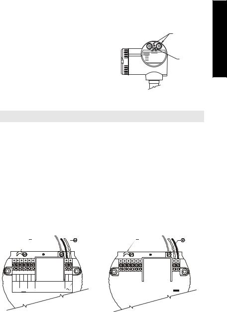
Connecting SITRANS LR 460
1.Release the cover lock on the enclosure with a 3 mm Allen key and unscrew the cover. (Use a screwdriver for extra leverage, if required.)
2.Loosen the cable gland and push the power cable through until it reaches the terminal strip.
cover |
|
lock |
cable gland |
|
|
metal bracket |
power |
terminal |
cable |
strip |
|
mmmmm Wiring
(Go to HART wiring on page 20 or PROFIBUS wiring on page 21 for next steps.)
7ML19985JM01 |
SITRANS LR 460 – INSTRUCTION MANUAL |
Page 19 |

mmmmm Wirng
HART wiring
Note: LR 460 HART requires no power from the 4-20 mA loop.
Install in accordance with Wiring and Installation in the HART Application Guide (order number HCF_LIT-34), available from: http://www.hartcomm.org/technical/doclist.html.
AC version |
|
DC version |
|
cable clamp |
earth |
cable clamp |
earth |
|
terminal |
|
terminal |
3 |
4 |
5 |
6 |
7 |
|
8 |
|
1 |
2 |
3 |
4 |
5 |
6 |
7 |
|
8 |
|
|
1 |
2 |
||||
|
|
|
|
|
||||||||||||||||||||
|
|
|
|
|
|
|
|
|
|
|
|
|
|
|||||||||||
|
|
|
|
|
|
|
|
Rated temperature of |
L1 |
L2 |
|
|
|
|
|
|
|
|
Rated temperature of |
|
|
|
|
|
|
|
|
|
mA |
|
connection cables must |
|
N |
|
|
|
|
|
|
|
|
|
|
|
|
||||
|
|
|
|
|
exceed maximum ambient |
|
|
|
|
|
mA |
|
connection cables must |
19-30 V |
||||||||||
|
|
|
|
|
|
|
|
|
|
|
|
|
|
|||||||||||
|
|
|
|
|
|
|
|
temperature by at least 15 K |
|
|
|
|
|
|
|
exceed maximum ambient |
||||||||
|
|
|
|
|
|
|
|
|
|
|
|
|
|
|
|
|
|
|
|
|
|
|||
temperature by at least 15 K
Connecting HART
Typical PLC/mA configuration with HART
Notes:
•For error-free communication via the HART protocol, a 250 Ohm resistor may be required if the loop resistance is less than 250 Ohms.
•Only one HART communication device should be inserted in the loop.
PLC with mA input card
PC/laptop with
R = 250 Ω HART modem running PDM
|
HART |
LR 460 |
Communicator |
|
375 |
3.Connect the earth conductor of the power supply to the earth terminal 
 on the metal bracket inside the enclosure. Adjust the cable length so that the earth conductor would be last to disconnect if cable is pulled.
Page 20 |
SITRANS LR 460 – INSTRUCTION MANUAL |
7ML19985JM01 |
4.Tighten the cable gland and check the strain relief (pull and turn).
5.Replace the enclosure cover and hand tighten it. The sealing ring must be clean and undamaged.
6.Tighten the screw on the cover lock.
7. |
Connect the external earth terminal located |
cable |
|
between the cable glands to a ground |
glands |
|
connection at your vessel. Use a cable with |
|
|
a cross-section of 2.5 mm2 or greater. |
earth |
|
|
|
|
|
(ground) |
|
|
terminal |
PROFIBUS wiring
Note: PROFIBUS PA is not polarity-sensitive.
Power Demands
To determine how many devices can be connected to a bus line, calculate the combined maximum current consumption of all the connected devices: 10.5 mA for SITRANS LR 460. Allow a current reserve for safety.
Bus Termination
PROFIBUS PA MUST be terminated at both extreme ends of the cable for it to work properly. Please refer to the PROFIBUS PA User and Installation Guidelines (order number 2.092), available from www.profibus.com.
Install in accordance with PROFIBUS PA User and Installation Guidelines (order number 2.092), available from www.profibus.com.
AC version |
|
DC version |
|
cable clamp |
earth |
cable clamp |
earth |
|
terminal |
|
terminal |
3 |
4 |
5 6 |
7 |
8 |
|
|
1 |
2 |
|
|
|
|
|
|
|
|
|
|
|
|
|
|
|
|
|
|
|
|
|
|
|
|
|||||||
|
|
3 |
4 |
5 |
6 |
7 |
8 |
|
1 |
2 |
|||||||||
|
|
|
|
|
Rated temperature of |
L1 |
L2 |
|
|
|
|
|
|
|
|
|
|
|
|
|
|
|
|
|
|
|
|
|
|
|
Rated temperature of |
|
|
|
|
||||
|
|
|
PROFI- |
connection cables must |
|
N |
|
|
|
|
PROFI- |
connection cables must |
19-30 V |
||||||
|
|
|
exceed maximum ambient |
|
|
|
|
|
|||||||||||
|
|
|
BUS PA |
temperature by at least 15 K |
|
|
|
|
|
|
BUS PA |
exceed maximum ambient |
|
|
|
|
|||
|
|
|
|
|
|
|
|
|
|
|
temperature by at least 15 K |
|
|
|
|
||||
|
|
|
|
|
|
|
|
|
|
|
|
|
|
|
|
|
|
|
|
|
|
|
|
|
|
|
|
|
|
|
|
|
|
|
|
|
|
|
|
mmmmm Wiring
7ML19985JM01 |
SITRANS LR 460 – INSTRUCTION MANUAL |
Page 21 |

mmmmm Wirng
Connecting PROFIBUS PA
Typical PLC/mA configuration with PROFIBUS PA
Class 1 |
PLC |
Class 2 |
Master |
PDM Master |
|
DP/PA |
|
PROFIBUS PA |
|
ET200 |
|
Coupler |
|
|
|
|
PROFIBUS PA |
|
|
HART |
SITRANS |
SITRANS |
SITRANS |
LR 460 |
LR 460 |
LR 460 |
(Continued from Connecting SITRANS LR 460 on page 19, step 2.)
3.Connect the earth conductor of the power supply to the earth terminal 
 on the metal bracket inside the enclosure. Adjust the cable length so that the earth conductor would be last to disconnect if cable is pulled.
4.Tighten the cable gland and check the strain relief (pull and turn).
5.Replace the enclosure cover and hand tighten it. The sealing ring must be clean and undamaged.
6.Tighten the screw on the cover lock.
7.Connect the external earth terminal located between the cable glands to a ground
connection at your vessel. Use a cable with a cross-section of 2.5 mm2 or greater.
cable glands
earth (ground) terminal
Page 22 |
SITRANS LR 460 – INSTRUCTION MANUAL |
7ML19985JM01 |
Hazardous area installations
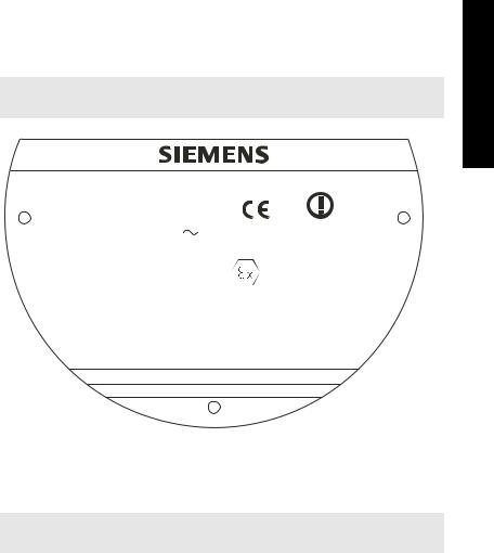
Product Nameplate
Note: The nameplate shown is a typical example. Please check the nameplate on your device for your specific device configuration.
SITRANS LR 460 Radar Level Meter
7ML5426-0AA00-0AC-0
Serial # GYZ/S1034567 |
0518 |
|
0891 |
||
Power Rating:100 - 230 V , ±15%, 50/60 Hz, 6 W |
||
Enclosure: |
TYPE/NEMA 4X, 6 / IP67 |
Canada 267P-LR460 |
Amb. Temp.: – 40°C to 65°C |
II 1D, 1/2 D, 2D |
|
|
|
|
Output: |
4 - 20 mA HART |
Ex tD A20 IP67 T85°C |
|
|
SIRA 06ATEX9218X |
IECEx SIR 06.0058X
Ex tD A20 IP67 T85°C
Do Not Open in an explosive dust atmosphere.
Siemens Milltronics Process Instruments Inc., Peterborough
Made in Canada
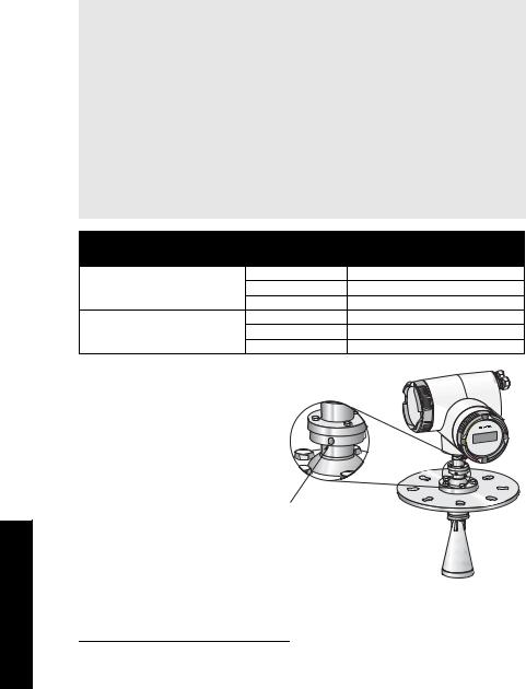
Instructions specific to hazardous area installations
(Reference European ATEX Directive 94/9/EC, Annex II, 1/0/6)
Note: Installation shall be performed only by qualified personnel and in accordance with local governing regulations.
The following instructions apply to equipment covered by certificate number
Sira 06 ATEX 9218X.
1.For use and assembly, refer to the main instructions.
2.The equipment is certified for use as Category II 1D, 1/2 D & 2D equipment. The Essential Health and Safety Requirements are assured by compliance with IEC 61241-0: 2004 and IEC 61241-1: 2004.
3.The equipment may be used with dust and fibers with apparatus temperature class T (see table below).
mmmmm Wiring
7ML19985JM01 |
SITRANS LR 460 – INSTRUCTION MANUAL |
Page 23 |

mmmmm Wirng
4. |
Thermal Data for 7ML5426 Series |
|
||
|
|
|
|
|
|
|
Device |
Permitted ambient |
Permitted ambient |
|
|
temperature at electronic |
||
|
|
category |
temperature at horn antenna |
|
|
|
enclosure |
||
|
|
|
|
|
|
|
|
|
|
|
|
1D, 1/2D, 2D |
–40 °C (–40 °F) ≤ Tamb ≤+200°C |
–40 °C (–40 °F) ≤ Tamb ≤ +65°C |
|
|
(+392 °F) |
(+149 °F) |
|
|
|
|
||
|
|
|
|
|
5. |
The equipment has not been assessed as a safety related device (as referred to by |
|||
|
|
Directive 94/9/EC Annex II, clause 1.5). |
|
|
6. |
Installation and inspection of this equipment shall be carried out by suitably trained |
|||
|
|
personnel in accordance with the applicable code of practice (EN 61241-14 and EN |
||
|
|
61241 –17 in Europe). |
|
|
7. |
Repair of this equipment shall be carried out by suitably trained personnel in |
|||
|
|
accordance with the applicable code of practice. |
|
|
8. |
Components to be incorporated into or used as replacements in the equipment shall |
|||
|
|
be fitted by suitably trained personnel in accordance with the manufacturer’s |
||
|
|
documentation. |
|
|
9. |
It is the user’s responsibility to ensure that a manual override is possible in order to |
|||
|
|
shut down the equipment, and that protective systems are incorporated within |
||
automatic processes which deviate from the intended operating conditions, provided that this does not compromise safety.
10. Equipment Marking: The equipment marking contains at least the information on the product label. See Product Nameplate on page 23.
11. If the equipment is likely to come into contact with aggressive substances, it is the user’s responsibility to take suitable precautions to prevent it from being adversely affected, and to ensure that the type of protection is not compromised.
• Aggressive substances include, for example, acidic liquids or gases that may attack metals, or solvents that may affect polymeric materials.
• Suitable precautions include, for example, regular checks as part of routine inspections, or establishing from the material’s data sheet that it is resistant to specific chemicals.
SPECIAL CONDITIONS FOR SAFE USE
The ‘X’ suffix to the certificate number relates to the following special condition(s) for safe use.
•Cable or conduit entries must meet the requirements of European Directive 94/9/EC for Group II, Category 1D, 1/2D, or 2D, as appropriate, and must maintain the overall IP rating of the enclosure.
•For applications that require the purge feature, the user shall implement a means to ensure that combustible dust from the hazardous area cannot enter the purge supply in such a way as to compromise the area classification.
Page 24 |
SITRANS LR 460 – INSTRUCTION MANUAL |
7ML19985JM01 |
Loading...