


SIDOOR ATD401W
Table of contents
 Loading...

___________________
___________________
___________________
___________________
___________________
___________________
___________________
___________________
___________________
___________________
___________________
___________________
Automatic door controllers
SIDOOR
ATD4xxW Door Controller for
Industrial Applications
System Manual
01/2017
A5E38080677
Preface
Sign posts
1
System overview
2
SIDOOR functions
3
Controllers
4
Geared motors
5
Power supply
6
SIDOOR Service Tool
7
Configuration and
programming in STEP 7
8
Connecting and
commissioning
9
Diagnostic and maintenance
10
Appendices
A
-AB
Siemens AG
Division Digital Factory
Postfach 48 48
90026 NÜRNBE
GERMANY
A5E38080677-AB
Ⓟ
Copyright © Siemens AG 2016 - 2017.
All rights reserved
Legal information
Warning notice system
DANGER
indicates that death or severe personal injury will result if proper precautions are not taken.
WARNING
indicates that death or severe personal injury may result if proper precautions are not taken.
CAUTION
indicates that minor personal injury can result if proper precautions are not taken.
NOTICE
indicates that property damage can result if proper precautions are not taken.
Qualified Personnel
personnel qualified
Proper use of Siemens products
WARNING
Siemens products may only be used for the applications described in the catalog and in the relevant technical
maintenance are required to ensure that the products operate safely and without any problems. The permissible
ambient conditions must be complied with. The information in the relevant documentation must be observed.
Trademarks
Disclaimer of Liability
This manual contains notices you have to observe in order to ensure your personal safety, as well as to prevent
damage to property. The notices referring to your personal safety are highlighted in the manual by a safety alert
symbol, notices referring only to property damage have no safety alert symbol. These notices shown below are
graded according to the degree of danger.
If more than one degree of danger is present, the warning notice representing the highest degree of danger will
be used. A notice warning of injury to persons with a safety alert symbol may also include a warning relating to
property damage.
The product/system described in this documentation may be operated only by
task in accordance with the relevant documentation, in particular its warning notices and safety instructions.
Qualified personnel are those who, based on their training and experience, are capable of identifying risks and
avoiding potential hazards when working with these products/systems.
Note the following:
documentation. If products and components from other manufacturers are used, these must be recommended
or approved by Siemens. Proper transport, storage, installation, assembly, commissioning, operation and
All names identified by ® are registered trademarks of Siemens AG. The remaining trademarks in this publication
may be trademarks whose use by third parties for their own purposes could violate the rights of the owner.
We have reviewed the contents of this publication to ensure consistency with the hardware and software
described. Since variance cannot be precluded entirely, we cannot guarantee full consistency. However, the
information in this publication is reviewed regularly and any necessary corrections are included in subsequent
editions.
for the specific
RG
02/2017 Subject to change

Preface
Content of the System Manual
Target group
Firmware versions
Note
You will find the current firmware versions for SIDOOR ATD4xxW
Online Sup
Figures
Information on the Internet
Parameter documentation
Recycling and disposal
This system manual describes:
● ATD4xxW control gear used for industrial applications
● Geared motors, power supplies, additional units that you can use with the control units.
The system manual is intended for fitters, commissioning engineers, operators, service
personnel and project engineers for protective machine doors.
This system manual applies to SIDOOR ATD4xxW industrial door control units as of
firmware version 1.03.
The illustrations in this system manual show the SIDOOR User Software Version 1.2 and the
SIDOOR command device. The illustrations for other versions may differ slightly.
You can find more information about SIDOOR door drives and their application on the
Internet (http://www.siemens.com/sidoor
Record the determined, optimal parameter settings in the configuration protocol (see
appendix "Configuration protocol (Page 309)"). Have this record to hand when you call the
Hotline.
control gear at Industry
port (http://support.automation.siemens.com/WW/view/en/50247080/133100).
).
The products are low in pollutants and are recyclable. To ensure eco-friendly recycling and
to dispose of your old device, contact a certified disposal company for electronic waste.
ATD4xxW Door Controller for Industrial Applications
4 System Manual, 01/2017, A5E38080677-AB

Preface
History
Revision of the system manual
Change
06/2016
First edition
Security information
Note
Using ATD410W, ATD420W und ATD430W fieldbus controllers
Installation in control cabinet only
01/2017 Revision of MDG700 NMS
Siemens offers products and solutions with industrial security functions that support secure
operation of plants, systems, machines and networks. In order to protect plants, systems,
machines and networks against cyber threats, it is necessary to implement – and
continuously maintain – a comprehensive, state-of-the-art industrial security concept.
Siemens’ products and solutions only form one element of such a concept. Customer is
responsible to prevent unauthorized access to its plants, systems, machines and networks.
Systems, machines and components should only be connected to the enterprise network or
the Internet if and to the extent necessary and with appropriate security measures (e.g. use
of firewalls and network segmentation) in place. Additionally, Siemens’ guidance on
appropriate security measures should be taken into account. You can find more information
on industrial security at (http://www.siemens.com/industrialsecurity
) .
Siemens’ products and solutions undergo continuous development to make them more
secure. Siemens strongly recommends to apply product updates as soon as available and to
always use the latest product versions. Use of product versions that are no longer supported,
and failure to apply latest updates may increase customer’s exposure to cyber threats. To
stay informed about product updates, subscribe to the Siemens Industrial Security RSS
Feed at (http://www.siemens.com/industrialsecurity
) .
– to ensure access by authorized personnel only.
ATD4xxW Door Controller for Industrial Applications
System Manual, 01/2017, A5E38080677-AB
5

Table of contents
Preface ................................................................................................................................................... 4
1 Sign posts ............................................................................................................................................. 12
2 System overview ................................................................................................................................... 14
3 SIDOOR functions ................................................................................................................................ 26
2.1 SIDOOR Door Control Systems ............................................................................................. 14
2.2 System configuration and area of application ........................................................................ 16
2.3 Products ................................................................................................................................. 18
2.3.1 Controllers .............................................................................................................................. 18
2.3.2 Geared motors ....................................................................................................................... 19
2.3.3 Power supply .......................................................................................................................... 20
2.3.4 Accessories ............................................................................................................................ 21
2.3.5 Optional additional units ......................................................................................................... 24
2.3.6 Software ................................................................................................................................. 25
3.1 Basic functions ....................................................................................................................... 29
3.1.1 Learn run ................................................................................................................................ 29
3.1.2 Force limit for learn run .......................................................................................................... 37
3.1.3 Output transmission ............................................................................................................... 38
3.1.4 Drive orders ............................................................................................................................ 39
3.1.5 DOOR CLOSE (command given via digital inputs) ............................................................... 43
3.1.6 DOOR OPEN (command given via digital inputs) ................................................................. 44
3.1.7 Stopping ................................................................................................................................. 45
3.1.8 Partial opening ....................................................................................................................... 45
3.1.9 Obstruction detection CLOSE ................................................................................................ 46
3.1.10 Obstruction detection OPEN .................................................................................................. 46
3.1.11 Force and energy profiles (NDG mode) ................................................................................. 47
3.1.12 Slow driving curve profile ....................................................................................................... 48
3.1.13 DCOPS (door closed/opened position sensor) ...................................................................... 49
3.2 System functions .................................................................................................................... 51
3.2.1 Restart after power failure ...................................................................................................... 51
3.2.2 Initial run/reference run (Power ON) ...................................................................................... 52
3.2.3 Overload protection of the geared motor ............................................................................... 52
3.2.4 Vandalism protection/continuous door monitoring ................................................................. 53
3.2.5 Belt break monitoring ............................................................................................................. 54
3.2.6 Friction compensation ............................................................................................................ 55
3.2.7 Oscillation protection .............................................................................................................. 56
3.2.8 Automatic energy limitation .................................................................................................... 57
3.2.9 External closing force .............................................................................................................
3.2.
10 Synchronization of the door position ...................................................................................... 60
3.2.11 Cyclic process values via fieldbus ......................................................................................... 61
60
ATD4xxW Door Controller for Industrial Applications
6 System Manual, 01/2017, A5E38080677-AB

Table of contents
3.3 Extended functions ................................................................................................................. 62
3.3.1 ImpulseDrive ........................................................................................................................... 62
3.3.2 Automatic ImpulseDrive .......................................................................................................... 64
3.3.3 ImpulseStop ............................................................................................................................ 65
3.3.4 Automatic ImpulseStop ........................................................................................................... 66
3.3.5 AssistedDrive .......................................................................................................................... 67
3.3.6 Automatic AssistedDrive ......................................................................................................... 69
3.3.7 Positioning mode .................................................................................................................... 70
3.3.8 Obstruction detection .............................................................................................................. 71
3.3.8.1 Obstruction detection process ................................................................................................ 72
3.3.8.2 Overcome obstruction ............................................................................................................. 72
3.3.8.3 Reversing (Retraction attempt) ............................................................................................... 73
3.3.8.4 Combination of retry and reverse ........................................................................................... 74
3.3.8.5 Slow obstruction approach ..................................................................................................... 74
3.3.8.6 Wait mode ............................................................................................................................... 74
3.3.8.7 Expert configuration ................................................................................................................ 75
3.3.9 Free function blocks (FBLOCK) .............................................................................................. 76
3.3.9.1 Overview ................................................................................................................................. 76
3.3.9.2 Configuring the logic ............................................................................................................... 78
3.3.9.3 Digital and logical input signals ............................................................................................... 80
3.3.9.4 Control bits .............................................................................................................................. 81
3.3.9.5 Special function blocks ........................................................................................................... 81
3.3.9.6 Discrepancy analysis blocks ................................................................................................... 81
3.3
.9.7 Basic blocks ............................................................................................................................ 81
3.3.9.8 Frequency analysis blocks ...................................................................................................... 82
3.3.9.9 On delay block ........................................................................................................................ 82
3.3.9.10 Counter block .......................................................................................................................... 83
3.3.10 Basic parameter editor (as of V1.10) ...................................................................................... 83
3.4 Safety functions ...................................................................................................................... 85
3.4.1 Optional safety equipment ...................................................................................................... 85
3.4.1.1 Light barrier ............................................................................................................................. 85
3.4.1.2 Type 2 ESPE .......................................................................................................................... 87
3.4.1.3 Pressure-sensitive edge (SR) ................................................................................................. 89
3.4.2 Security policy ......................................................................................................................... 90
3.4.2.1 Safe force output ..................................................................................................................... 90
3.4.2.2 Safe speed observance (energy limiting) ............................................................................... 90
3.4.2.3 Safe input signals according to PLd ....................................................................................... 91
3.4.2.4 Internal signal routing.............................................................................................................. 91
3.4.2.5 Redundant antivalent signal logic with discrepancy analysis ................................................. 92
3.4.2.6 Frequency-based input signals ............................................................................................... 93
3.4.2.7 Two-hand operation concept (according to Cat. IIIA) ............................................................. 94
3.4.2.8 Emergency stop concept in accordance with stop category 1 ............................................... 96
3.4.2.9 Concept of fail-safe digital control (door OPEN/CLOSE) with emergency stop via 4
digital inputs ............................................................................................................................ 98
3.4.2.10 Concept of fail-safe digital control (door OPEN/CLOSE) with emergency stop via 3
digital inputs .......................................................................................................................... 101
ATD4xxW Door Controller for Industrial Applications
System Manual, 01/2017, A5E38080677-AB
7

Table of contents
4 Controllers ........................................................................................................................................... 103
4.1 Description of controller ....................................................................................................... 103
4.2 Installing the control unit ...................................................................................................... 104
4.3 Wiring instructions ................................................................................................................ 107
4.4 Connecting terminals ........................................................................................................... 108
4.4.1 Digital input signals .............................................................................................................. 108
4.4.2 Voltage output ...................................................................................................................... 111
4.5 Relay and fieldbus interfaces ............................................................................................... 112
4.5.1 Relay module ....................................................................................................................... 112
4.5.2 USS ...................................................................................................................................... 116
4.5.2.1 USS module ......................................................................................................................... 116
4.5.2.2 Wiring and connecting the USS plug ................................................................................... 118
4.5.2.3 Wiring and connecting relay outputs .................................................................................... 120
4.5.3 PROFIBUS ........................................................................................................................... 121
4.5.3.1 PROFIBUS module .............................................................................................................. 121
4.5.3.2 Wiring and connecting PROFIBUS connectors ................................................................... 125
4.5.3.3 Wiring and connecting relay outputs .................................................................................... 127
4.5.3.4 PROFIBUS communication ................................................................................................. 129
4.5.4 PROFINET ........................................................................................................................... 134
4.5.4.1 PROFINET module .............................................................................................................. 134
4.5.4.2 Wiring and connecting a PROFINET connector .................................................................. 141
4.5.4.3 Wiring and connecting relay outputs .................................................................................... 142
4.5.4.4 PROFINET communication .................................................................................................. 144
4.5.5 Local/master operation ........................................................................................................ 148
4.5.6 Master monitoring ................................................................................................................ 148
4.6 S
equential control ................................................................................................................ 149
4.7 Sensors and external sensor interface module ................................................................... 152
4.7.1 Overview .............................................................................................................................. 152
4.7.2 Sensor function test ............................................................................................................. 155
4.7.3 Reaction times ..................................................................................................................... 156
4.7.4 Stopping distances ............................................................................................................... 156
4.8 Technical specifications ....................................................................................................... 157
4.9 Operation and configuration of the control unit .................................................................... 161
4.9.1 Service buttons .................................................................................................................... 161
4.9.1.1 Operation using service buttons .......................................................................................... 162
4.9.2 Parameter assignment via the terminal module .................................................................. 165
4.9.3 Parameter assignment using additional devices ................................................................. 167
4.9.4 Parameter names................................................................................................................. 167
4.9.5 Adjustable parameters ......................................................................................................... 169
4.9.5.1 Driving curve ........................................................................................................................ 169
4.9.5.2 Forces .................................................................................................................................. 170
4.9.5.3 Parameter assignment ......................................................................................................... 174
4.9.5.4 Parameter assignment for special applications ................................................................... 188
ATD4xxW Door Controller for Industrial Applications
8 System Manual, 01/2017, A5E38080677-AB

Table of contents
5 Geared motors .................................................................................................................................... 189
6 Power supply ...................................................................................................................................... 217
5.1 Description ............................................................................................................................ 189
5.2 Installation ............................................................................................................................. 190
5.3 Connecting terminals ............................................................................................................ 195
5.3.1 Conductor assignment of the motor plug .............................................................................. 195
5.4 Technical specifications ........................................................................................................ 196
5.4.1 Dimension drawing of SIDOOR M3 with rubber-metal anti-vibration mount and
mounting bracket .................................................................................................................. 205
5.4.2 Dimension drawing of SIDOOR MDG180 with rubber-metal anti-vibration mount and
mounting bracket .................................................................................................................. 206
5.4.3 Dimension drawing of SIDOOR M4 with rubber-metal anti-vibration mount and
mounting bracket .................................................................................................................. 207
5.4.4 Dimension drawing of SIDOOR MDG400 with rubber-metal anti-vibration mount and
mounting bracket .................................................................................................................. 208
5.4.5 Dimension drawing MDG400NMS ........................................................................................ 209
5.4.6 Dimension drawing of SIDOOR MDG400 NMS with rubber-metal anti-vibration mount
and mounting bracket ........................................................................................................... 210
5.4.7 Dimension drawing of SIDOOR M5 ...................................................................................... 211
5.4.8 Dimension drawing of SIDOOR MDG700 NMS ................................................................... 212
5.4.9 Dimension drawing of MDG motor cable .............................................................................. 213
5.4.10 Dimension drawing of motor cable MDG2 ............................................................................ 214
5.4.11 Dimension drawing of deflector pulley with tensioning device and mounting bracket .......... 215
5.4.12 Dimension drawing of door clutch holder.............................................................................. 216
6.1 SIDOOR NT40 ...................................................................................................................... 217
6.1.1 Description ............................................................................................................................ 217
6.1.2 Installation ............................................................................................................................. 219
6.1.3 Connecting terminals ............................................................................................................ 220
6.1.4 Technical specifications ........................................................................................................ 222
6.2 SIDOOR Transformer ........................................................................................................... 225
6.2.1 Description ............................................................................................................................ 225
6.2.2 Installation ............................................................................................................................. 226
6.2.3 Connecting terminals ............................................................................................................ 227
6.2.4 Technical specifications ........................................................................................................ 228
6.3 SITOP PSU8200 13A/36V 3-phase ...................................................................................... 231
6.3.1 Power supply requirements of SITOP PSU8200 .................................................................. 232
6.3.2 Installation ............................................................................................................................. 232
6.3.3 Technical specifications ........................................................................................................ 233
6.4 Building DC voltage supply ................................................................................................... 236
6.4.1 Power supply requirements .................................................................................................. 237
6.4.2 Installation ............................................................................................................................. 239
6.5 Uninterruptible power supply (UPS) ..................................................................................... 239
ATD4xxW Door Controller for Industrial Applications
System Manual, 01/2017, A5E38080677-AB
9

Table of contents
7 SIDOOR Service Tool .......................................................................................................................... 243
8 Configuration and programming in STEP 7 .......................................................................................... 254
9 Connecting and commissioning ............................................................................................................ 259
10 Diagnostic and maintenance ................................................................................................................ 273
7.1 Description ........................................................................................................................... 243
7.2 Connection ........................................................................................................................... 243
7.3 Operation ............................................................................................................................. 244
7.4 Navigation structure in the SIDOOR Service Tool ............................................................... 246
7.5 Technical specifications ....................................................................................................... 253
8.1 PROFINET integration via GSD file ..................................................................................... 254
8.2 PROFIBUS integration via GSD file ..................................................................................... 255
8.3 Programming SIDOOR instructions ..................................................................................... 256
8.3.1 "SIDOOR_CDat" data type .................................................................................................. 257
8.3.2 "SIDOOR_SDat" data type ................................................................................................... 258
9.1 Overview of safety and commissioning ............................................................................... 259
9.2 Preparing the control unit ..................................................................................................... 263
9.3 Connecting a geared motor to the control unit ..................................................................... 264
9.4 Connecting the power supply to the network and executing a learn run ............................. 266
9.5 Connecting digital inputs ...................................................................................................... 267
9.6 Commissioning the control unit on the fieldbus ................................................................... 268
9.7 Final settings and checks ..................................................................................................... 271
10.1 Operating state display ........................................................................................................ 273
10.2 Fault management ............................................................................................................... 274
10.3 Maintenance ......................................................................................................................... 275
ATD4xxW Door Controller for Industrial Applications
10 System Manual, 01/2017, A5E38080677-AB

Table of contents
A Appendices ......................................................................................................................................... 276
Index................................................................................................................................................... 317
A.1 Structure of user data/process data ...................................................................................... 276
A.1.1 Parameter interface .............................................................................................................. 277
A.1.1.1 Parameter ID (PKE) .............................................................................................................. 278
A.1.1.2 Parameter index (IND) .......................................................................................................... 281
A.1.1.3 Parameter value (PWE) ........................................................................................................ 283
A.1.1.4 Parameter ID ......................................................................................................................... 284
A.1.1.5 Parameter description (PBE) ................................................................................................ 284
A.1.2 Process data ......................................................................................................................... 285
A.1.2.1 STW1 - control word (CtrlW) ................................................................................................. 286
A.1.2.2 TSW0 - technology control word 0 ........................................................................................ 287
A.1.2.3 TSW1 - technology control word 1 ........................................................................................ 287
A.1.2.4 TSW2 - technology control word 2 ........................................................................................ 289
A.1.2.5 ZSW1 - status word (StatW) ................................................................................................. 290
A.1.2.6 TZW0 - Technology status word 0 ........................................................................................ 292
A.1.2.7 TZW1 - Technology status word 1 ........................................................................................ 292
A.1.2.8 TZW2 - Technology status word 2 ........................................................................................ 295
A.1.2.9 TZW3, TZW4, TZW5 - Technology status words 3, 4, 5 ...................................................... 297
A.2 Profiles and adjustment ranges ............................................................................................ 299
A.2.1 Profile name .......................................................................................................................... 299
A.2.2 SIDOOR M3 L / R ................................................................................................................. 299
A.2.3 SIDOOR MDG180 L / R ........................................................................................................ 301
A.2.4 SIDOOR M4 L / R ................................................................................................................. 301
A.2.5 SIDOOR MDG400 L / R ........................................................................................................
A.2
.6 SIDOOR MDG400NMS L / R ................................................................................................ 303
302
A.2.7 SIDOOR M5 L / R ................................................................................................................. 305
A.2.8 SIDOOR MDG700NMS L / R ................................................................................................ 307
A.3 Configuration record ............................................................................................................. 309
A.4 Standards, directives and laws ............................................................................................. 311
A.4.1 Safety .................................................................................................................................... 311
A.4.2 EMC ...................................................................................................................................... 312
A.4.3 Communications ................................................................................................................... 312
A.4.4 Application-specific standards .............................................................................................. 313
A.4.5 Protective devices ................................................................................................................. 314
A.5 Service & support .................................................................................................................. 316
ATD4xxW Door Controller for Industrial Applications
System Manual, 01/2017, A5E38080677-AB
11

1
Introduction
System manuals
Quick start operating instructions
Documentation download
"mySupport" documentation
The documentation serves the three areas of applications for SIDOOR products:
● Door controllers for industrial applications
● Door controllers for elevators
● Door controllers for rail applications
For each area of application, there are system manuals that describe the SIDOOR system
along with the units that can be used and their commissioning.
The quick start operating instructions provide an overview of the SIDOOR devices:
● The devices that you can use together
● The article numbers for ordering these devices
● Information on installation
● Important safety information
● Where you can get more information about the devices
This documentation is available for download free-of-charge on the Internet:
(http://www.siemens.com/automation/service&support
Changes and additions to the manuals are documented in a product information file.
In the Documentation area in "mySupport" you can combine entire manuals or only parts of
these to your own manual.
You can export the manual as PDF file or in a format that can be edited later.
You can find "mySupport" - Documentation on the Internet
(http://support.industry.siemens.com/My/ww/en/documentation
)
).
ATD4xxW Door Controller for Industrial Applications
12 System Manual, 01/2017, A5E38080677-AB

Sign posts
Applications & Tools
Applications & Tools support you with various tools and examples for solving your
automation tasks. Solutions are shown in interplay with multiple components in the system separated from the focus on individual products.
You can find Applications & Tools on the Internet
(https://support.industry.siemens.com/cs/ww/en/ps/18286/ae
)
ATD4xxW Door Controller for Industrial Applications
System Manual, 01/2017, A5E38080677-AB
13

2
2.1
SIDOOR Door Control Systems
What is SIDOOR?
What is a door control system?
SIDOOR for industrial applications
The SIDOOR product series is a door control system mainly for operation of sliding doors as
well as lifting and roller doors. SIDOOR door drives are drives for doors and gates in various
areas of application.
Door control system is the general term for the controller of an access system.
Door control systems are characterized by the fact that there are always two defined states,
namely for the open and closed positions of the door. The door is always controlled between
these two positions in accordance with the guidelines of the respective
Door control systems for industrial applications are designed mainly for protective machine
doors. In accordance with the integration of the machine in industrial communication
networks, the controllers can be integrated in the networks with different communication
options, including safety functionality.
application.
ATD4xxW Door Controller for Industrial Applications
14 System Manual, 01/2017, A5E38080677-AB

System overview
Customer benefits
2.1 SIDOOR Door Control Systems
● The controllers are optimally configured for their areas of application. With SIDOOR,
doors are always checked and controlled in an application-specific manner.
● Our intelligent system solution calculates the optimal drive characteristics for a door
automatically, and ensures that these are continuously maintained – in accordance with
the guidelines of the application.
● The entire commissioning process requires just the push of a single button. In a defined
learn run, the door system independently determines the values for the door width, the
dynamic mass to be moved and the drive direction of the geared motor, and stores these
data in a non-volatile memory.
● Assisted Drive and Impulse Stop support the movement of the heaviest doors without
buttons or sensors. Impulse Drive allows doors to be opened at closed with a brief, light
touch. The door moves completely autonomously.
● The screwless enclosure concept, with plug-in terminal connectors, allows the device to
be opened and closed without tools, thereby reducing installation times.
● Thanks to the independence of the door system, SIDOOR is highly flexible and can be
easily expanded with modular communication interfaces. SIDOOR door controllers can
be completely controlled by a SIMATIC S7 controller. The control, configuration and
diagnostics is performed via USS, PROFIBUS or PROFINET.
● The system's reliability, ruggedness and long-term precision minimize the need for
maintenance and repair work. Obstruction and belt tear detection provides more safety.
ATD4xxW Door Controller for Industrial Applications
System Manual, 01/2017, A5E38080677-AB
15
System overview
2.2
System configuration and area of application
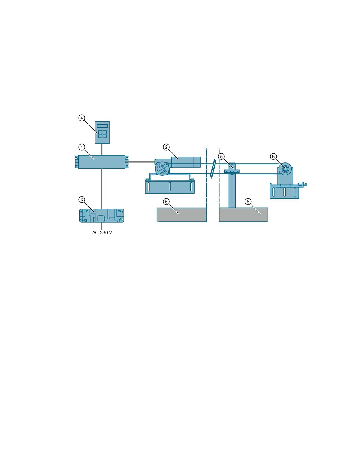
Overview of system configuration
①
④
Software Kit)
②
Geared motor
⑤
Accessories
③
Power supply
⑥
Sliding door
System configuration with a communication link
System configuration with safety functionality
2.2 System configuration and area of application
The graphic uses an example of a machine protection door to illustrate the general
configuration of automatic door control with the SIDOOR system including additional
components, such as a power supply and drive.
Controller
Figure 2-1 System configuration
Optional additional unit (e.g. SIDOOR Service Tool, SIDOOR
A system configuration with a communication link to the higher-level control, such as
SIMATIC S7 via PROFIBUS or PROFINET, is furthermore possible.
SIDOOR also provides a system configuration with safety functionality since safe limitation of
forces and energies and the safe end position determination is guaranteed within the drive
system.
The system allows for the implementation of additional customized safety measures, such as
two-hand operation.
ATD4xxW Door Controller for Industrial Applications
16 System Manual, 01/2017, A5E38080677-AB

System overview
Industrial applications
SIDOOR ATD4xxW
SIDOOR ATD401W
SIDOOR ATD410W
USS bus
SIDOOR ATD420W
PROFIBUS DP
SIDOOR ATD430W
PROFINET IO
2.2 System configuration and area of application
We offer the following control units for industrial applications:
The ATD4xxW are "intelligent" door drives. They are used, for example, to drive machine
protection doors. The safe functions - force limitation, energy limitation and end position
detection - fulfill the requirements according to DIN EN ISO 13849-1:2008 for Category 2
and Performance Level d. The drives are suitable for power-operated guards according to
EN 953:1997+A1:2009 section 5.2.5.2 "Actuating forces".
The SIDOOR ATD4xxW door controller enables connection to diverse fieldbus systems. This
makes integration into the industrial//SIMATIC environment possible. PROFINET IO,
PROFIBUS DP and USS are currently specified as fieldbuses. The PROFIdrive "variablespeed drives" profile is generally used as the higher-level device profile.
●
The "offline" relay variant can be used for simple automation tasks. As there is no
possibility of interfacing to a bus, it provides a limited scope of functions.
●
The controller is interfaced to a
by means of a permanently integrated USS
module.
You can find additional information about the USS protocol online at Industry Online
Support (http://support.automation.siemens.com/WW/view/de/24178253/0/en
●
The
interface is realized with a permanently integrated PROFIBUS
).
module. This module comes with its own firmware.
●
The
interface is realized with a permanently integrated PROFINET
module. This module comes with its own firmware.
The contents and structure of the user data transferred by the fieldbus systems correspond
to the PROFIdrive "variable speed drives" profile. Use of this profile is also the basis for
integration of the controller in the industrial environment. Both communicative integration via
a fieldbus system and safety-related aspects play an important role here.
SIDOOR ATD4xxW machine door drives enable connection of door closed/opened position
sensors (DCOPS), simple light barriers, pressure-sensitive edges as well as type 2 light
arrays in compliance with IEC 61496 (ESPE - electro-sensitive protective equipment).
The SIDOOR ATD410W, SIDOOR ATD420W and SIDOOR ATD430W machine door drives
are characterized by their many functions, including "AssistedDrive" (motor-assisted sliding
of the door) and "ImpulseDrive" (automatic door movement initiated by applying light force).
ATD4xxW Door Controller for Industrial Applications
System Manual, 01/2017, A5E38080677-AB
17
System overview
2.3
Products
2.3.1
Controllers
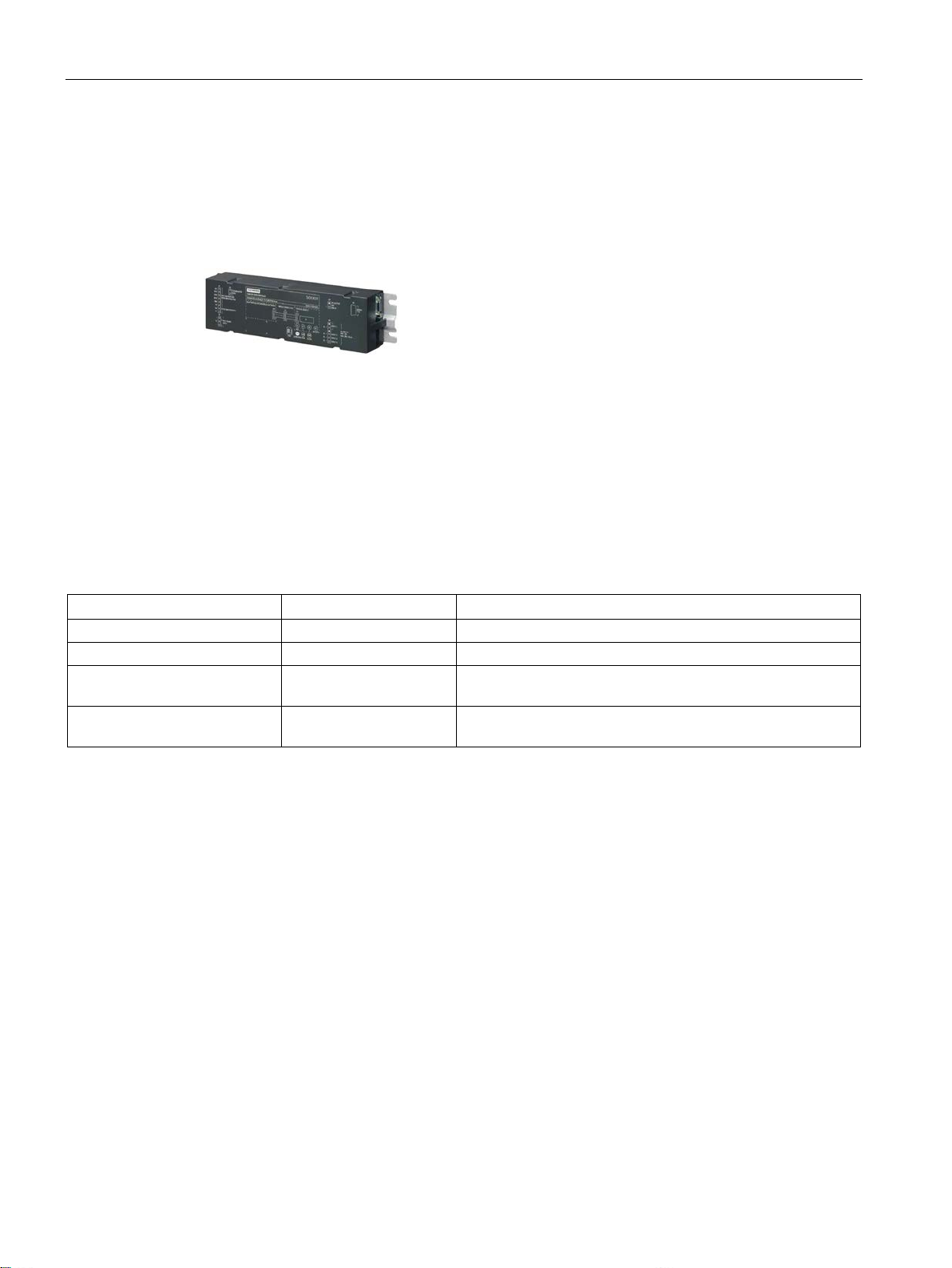
Controllers for industrial applications
Controller
Article No.
Description
SIDOOR ATD401W
6FB1141-1AT11-3WE2
Relay module
SIDOOR ATD410W
6FB1141-4AT10-3WE2
USS bus interface to the higher-level controller (USS module)
(PROFIBUS module)
(PROFIBUS module)
2.3 Products
Control units are electronic controllers connected to the power supply via an external power
supply unit (e.g. SITOP PSU 8200, SIDOOR NT40). They are generally connected to the
higher-level controller via digital or fieldbus interfaces, and can be configured via a user
interface.
The controllers are designed for different areas of application.
The following table provides an overview of the control units for doors in industrial
applications.
SIDOOR ATD420W 6FB1141-2AT10-3WE2 PROFIBUS interface to the higher-level controller
SIDOOR ATD430W 6FB1141-3AT10-3WE2 PROFINET interface to the higher-level controller
ATD4xxW Door Controller for Industrial Applications
18 System Manual, 01/2017, A5E38080677-AB
System overview
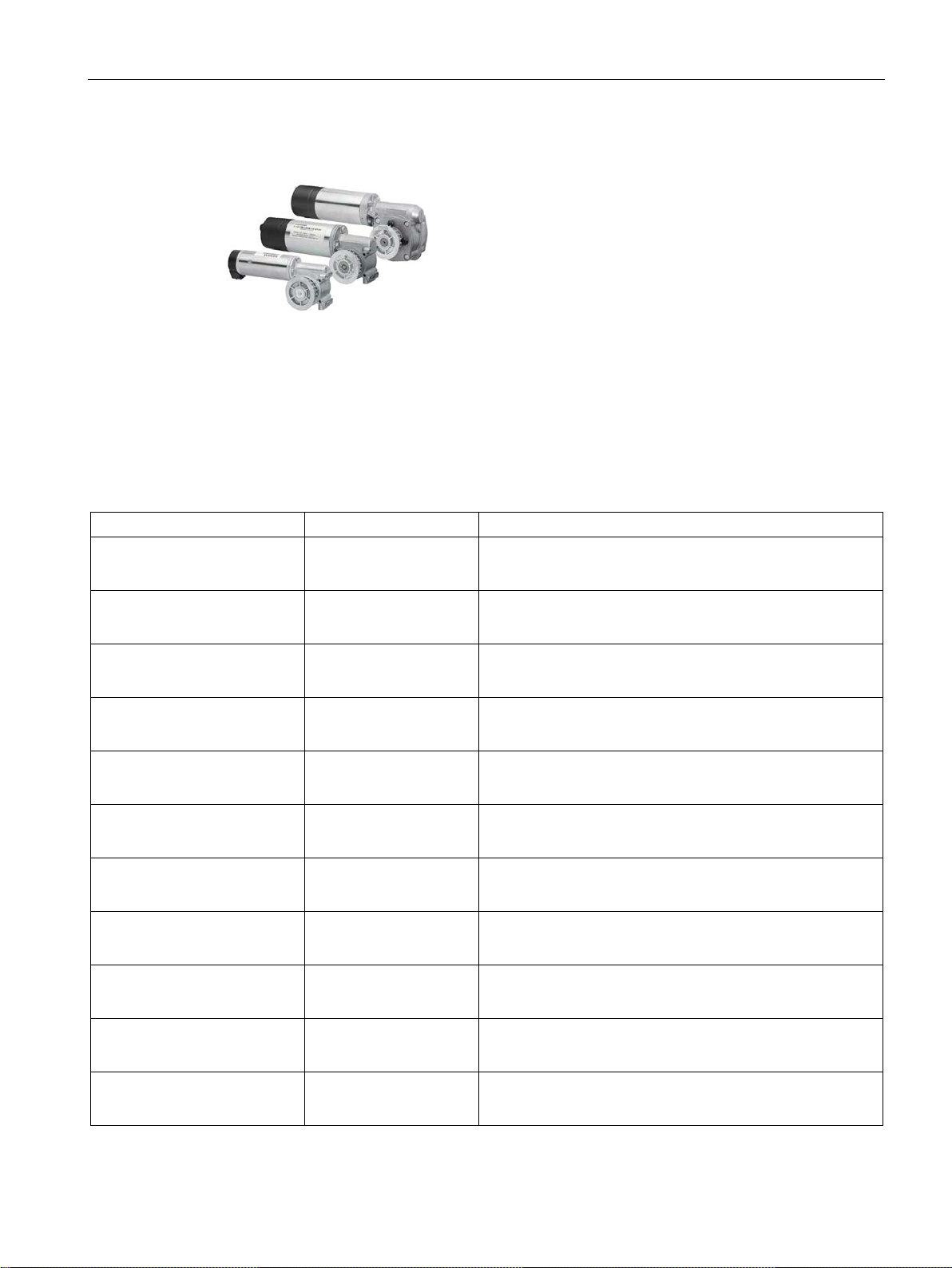
2.3.2
Geared motors
Versions
Geared motor
Article No.
Description
2.3 Products
Geared motors form the maintenance-free drive unit in the door drive. The geared motors
feature DC motors with non-self-locking gearing and are speed-controlled. The set force and
speed limits are not exceeded.
Power is transmitted to the door with a gear rack or chain. Toothed belts or chains pass over
a deflector pulley, and can be fitted with 2 clutch holders. This enables it to drive both singlesided and centrally-opening doors.
SIDOOR M3 L 6FB1103-0AT10-4MB0
SIDOOR M3 R 6FB1103-0AT11-4MB0
SIDOOR MDG180 L 6FB1103-0AT14-4MB0
SIDOOR MDG180 R 6FB1103-0AT13-4MB0
SIDOOR M4 L 6FB1103-0AT10-3MC0
SIDOOR M4 R 6FB1103-0AT11-3MC0
SIDOOR MDG400 L 6FB1103-0AT14-3MC0
SIDOOR MDG400 R 6FB1103-0AT13-3MC0
SIDOOR MDG400 NMS L 6FB1103-0AT14-3MC1
SIDOOR MDG400 NMS R 6FB1103-0AT13-3MC1
SIDOOR M5 L 6FB1103-0AT10-3MD0
• Geared motor, pinion left, max. 180 kg door weight
• Cable length 1.5 m
• Geared motor, pinion right, max. 180 kg door weight
• Cable length 1.5 m
• Geared motor, pinion left, max. 180 kg door weight
• Without cable*
• Geared motor, pinion right, max. 180 kg door weight
• Without cable*
• Geared motor, pinion left, max. 400 kg door weight
• Cable length 1.5 m
• Geared motor, pinion right, max. 400 kg door weight
• Cable length 1.5 m
• Geared motor, pinion left, max. 400 kg door weight
• Without cable*
• Geared motor, pinion right, max. 400 kg door weight
• Without cable*
• Geared motor, without pinion, max. 400 kg door weight
• Without cable*
• Geared motor, without pinion, max. 400 kg door weight
• Without cable*
• Geared motor, pinion left, max. 600 kg door weight
• Cable length 1.5 m
ATD4xxW Door Controller for Industrial Applications
System Manual, 01/2017, A5E38080677-AB
19
System overview
Geared motor
Article No.
Description
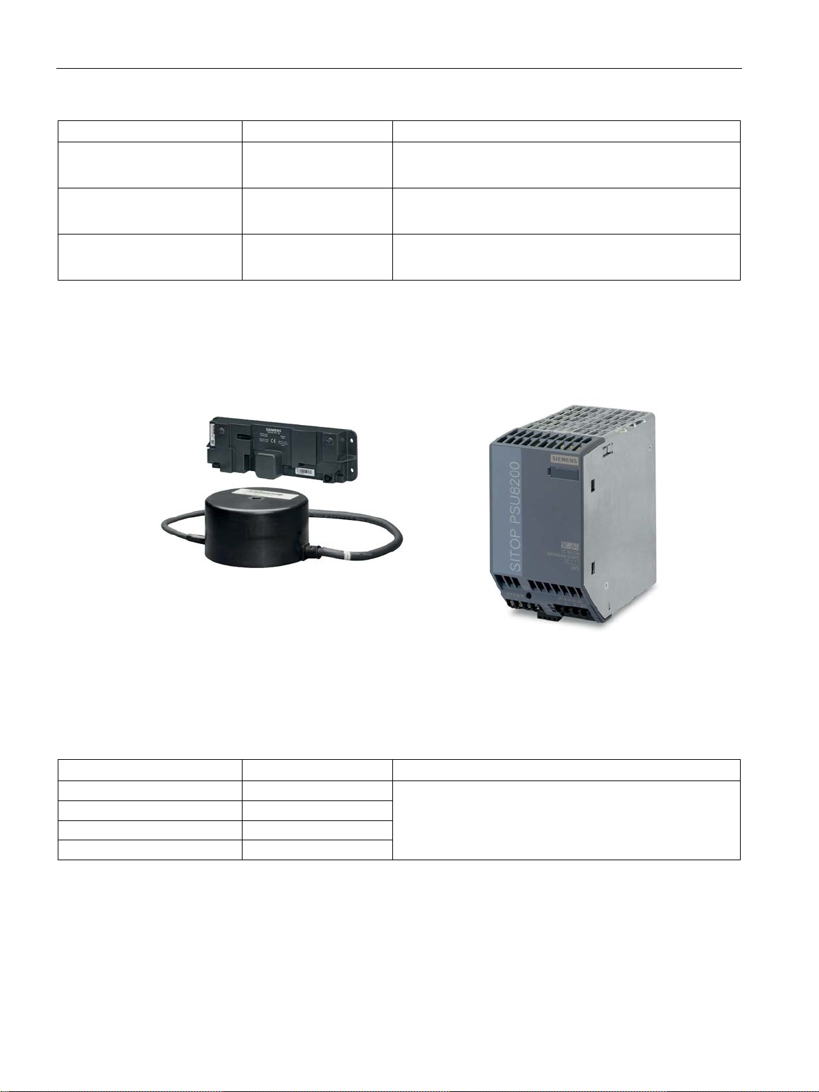
2.3.3
Power supply
Device selection
Power supply
Article No.
Description
SITOP PSU8200
6EP3446-8SB10-0AY0
SIDOOR NT40
6FB1112-0AT20-3PS0
DC voltage supply
-
2.3 Products
SIDOOR M5 R 6FB1103-0AT11-3MD0
SIDOOR MDG700 NMS R 6FB1103-0AT13-3MG1
SIDOOR MDG700 NMS L 6FB1103-0AT14-3MG1
* Cable can be ordered: See section Accessories (Page 21)
#
• Geared motor, pinon right, max. 600 kg door weight
• Cable length 1.5 m
• Geared motor, without pinion, max. 700 kg door weight
• Without cable*
• Geared motor, without pinion, max. 700 kg door weight
• Without cable*
SIDOOR power supplies connect the controllers to the respective application-specific power
supply.
SIDOOR Transformer 6FB1112-0AT20-2TR0
Power supply for controllers without an integrated power
supply unit.
ATD4xxW Door Controller for Industrial Applications
20 System Manual, 01/2017, A5E38080677-AB

System overview
2.3.4
Accessories
Accessories
Article No.
Description
motor is mounted
unit)
units)
2.3 Products
SIDOOR rubber-metal antivibration mount
SIDOOR mounting bracket 6FB1104-0AT01-0AS0 Mounting bracket for mounting the SIDOOR rubber-metal
SIDOOR deflector pulley 6FB1104-0AT04-0AS2 Deflector pulley for deflecting the SIDOOR toothed belt (1
SIDOOR deflector pulley 6FB1104-0AT04-0AS1 Deflector pulley for deflecting the SIDOOR toothed belt (30
SIDOOR deflector unit 6FB1104-0AT03-0AS0
SIDOOR door clutch holder 6FB1104-0AT01-0CP0
6FB1104-0AT01-0AD0
6FB1104-0AT02-0AD0
6FB1104-0AT02-0AS0
6FB1104-0AT02-0CP0
• Rubber-metal anti-vibration mount for quiet operation of
the door drive system
• Recommended for mounting geared motors
SIDOOR M4 R / L, MDG400 R / L, M5 R / L, MDG400
NMS R / L and MDG700 NMS R / L
• Rubber-metal anti-vibration mount for quiet operation of
the door drive system
• Recommended for mounting SIDOOR M3 R / L and
MDG180 R / L gear motors
anti-vibration mount on which, in turn, a SIDOOR geared
• Mounting bracket with tensioning device for deflector
pulley
• For mounting the SIDOOR deflector unit and for tension-
ing the SIDOOR toothed belt
• Deflector unit with deflector pulley
• For deflecting the SIDOOR toothed belt in the same
height and depth, aligned with motor drive pinion
• Door clutch holder for 12 mm-wide toothed belt
• For attaching both ends of the toothed belt, and for con-
necting the respective door panel to the toothed belt
• Door clutch holder for 14 mm wide toothed belt
• For attaching both ends of the toothed belt, and for con-
necting the respective door panel to the toothed belt
ATD4xxW Door Controller for Industrial Applications
System Manual, 01/2017, A5E38080677-AB
21

System overview
Accessories
Article No.
Description
2.3 Products
SIDOOR toothed belt 6FB1104-0AT01-0AB0
6FB1104-0AT02-0AB0
6FB1104-0AT03-0AB0
6FB1104-0AT04-0AB0
SIDOOR CABLE-MDG-0.5m 6FB1104-0AT00-0CB5
SIDOOR CABLE-MDG-1.5m 6FB1104-0AT01-0CB5
SIDOOR CABLE-MDG-5m 6FB1104-0AT05-0CB0
SIDOOR CABLE-MDG-7m 6FB1104-0AT07-0CB0
SIDOOR CABLE-MDG-10m 6FB1104-0AT10-0CB0
SIDOOR CABLE-MDG-15m 6FB1104-0AT15-0CB0
SIDOOR CABLE-MDG-20m 6FB1104-0AT20-0CB0
• Single-toothed STS
• Super Torque toothed belt
• Length 4 m, width 12 mm.
• Single-toothed STS
• Super Torque toothed belt
• Length 45 m, width 12 mm.
• Single-toothed STS
• Super Torque toothed belt
• Length 4 m, width 14 mm.
• Single-toothed STS
• Super Torque toothed belt
• Length 55 m, width 14 mm.
• Cable for connecting SIDOOR MDG180 R / L, MDG400 R
/ L / MDG400 NMS geared motors to SIDOOR ATD4xxW
controllers
• Cable length 0.5 m
• Cable for connecting SIDOOR MDG180 R / L, MDG400 R
/ L / MDG400 NMS geared motors to SIDOOR ATD4xxW
controllers
• Cable length 1.5 m
• Cable for connecting SIDOOR MDG180 R / L, MDG400 R
/ L / MDG400 NMS geared motors to SIDOOR ATD4xxW
controllers
• Cable length 5 m
• Cable for connecting SIDOOR MDG180 R / L, MDG400 R
/ L / MDG400 NMS geared motors to SIDOOR ATD4xxW
controllers
• Cable length 7 m
• Cable for connecting SIDOOR MDG180 R / L, MDG400 R
/ L / MDG400 NMS geared motors to SIDOOR ATD4xxW
controllers
• Cable length 10 m
• Cable for connecting SIDOOR MDG180 R / L, MDG400 R
/ L / MDG400 NMS geared motors to SIDOOR ATD4xxW
controllers
• Cable length 15 m
• Cable for connecting SIDOOR MDG180 R / L, MDG400 R
/ L / MDG400 NMS geared motors to SIDOOR ATD4xxW
controllers
• Cable length 20 m
ATD4xxW Door Controller for Industrial Applications
22 System Manual, 01/2017, A5E38080677-AB

System overview
Accessories
Article No.
Description
to the USS / PROFIBUS bus cable
controller
cable
higher-level SIMATIC controller
controllers
2.3 Products
SIDOOR CABLE-MDG2-5m 6FB1104-0AT05-0CB2
SIDOOR CABLE-MDG2-10m 6FB1104-0AT10-0CB2
SIDOOR CABLE-MDG2-15m 6FB1104-0AT15-0CB2
SIDOOR CABLE-MDG2- 20m 6FB1104-0AT20-0CB2
PROFIBUS FC bus connector
RS 485
PROFIBUS FC Standard Cable
GP
IE FC RJ45 plug 180 4X2 6GK1901-1BB11-2AB0 Plug connector with axial cable outlet (180°) for connecting
6GK1500-0FC10 Bus connector with axial cable outlet (180°, 20m) for connect-
6XV1830-0EH10 PROFIBUS cable for connecting SIDOOR ATD410W and
• Cable for connecting SIDOOR MDG700 NMS geared
motors and SIDOOR ATD4xxW control units
• Cable length 5 m
• Cable for connecting SIDOOR MDG700 NMS geared
motors and SIDOOR ATD4xxW control units
• Cable length 10 m
• Cable for connecting SIDOOR MDG700 NMS geared
motors and SIDOOR ATD4xxW control units
• Cable length 15 m
• Cable for connecting SIDOOR MDG700 NMS geared
motors and SIDOOR ATD4xxW control units
• Cable length 20 m
ing SIDOOR ATD410W and SIDOOR ATD420W controllers
SIDOOR ATD420W controllers to the higher-level SIMATIC
the SIDOOR ATD430W controller to the PROFINET bus
IE FC TP Standard Cable GP 6XV1878-2A Cable for connecting the SIDOOR ATD430W controller to the
DIN rail holder 6FB1144-0AT00-3AS0 DIN rail holder with fixing screws for SIDOOR ATD4xxW
You will find more accessories in the Industry Mall (http://www.siemens.com/siplus/mall)
ATD4xxW Door Controller for Industrial Applications
System Manual, 01/2017, A5E38080677-AB
23
System overview
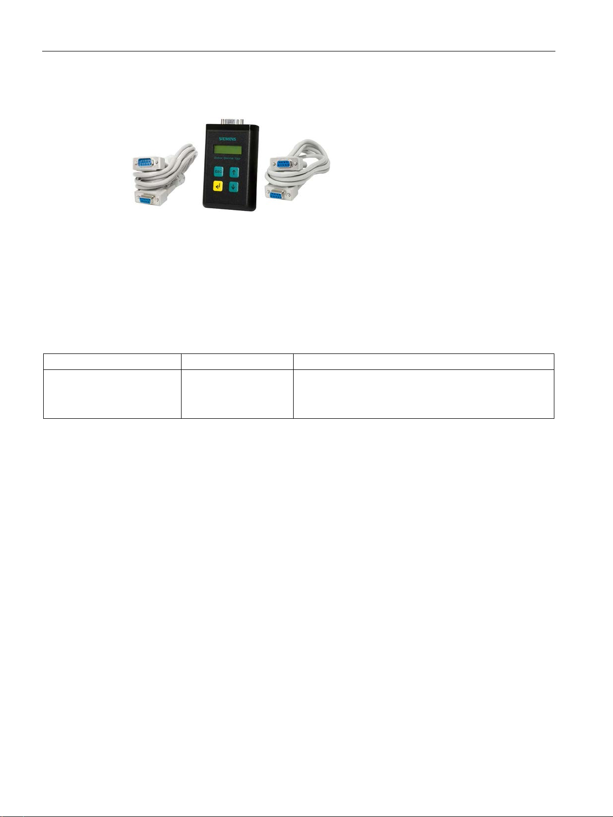
2.3.5
Optional additional units
Additional units
Additional unit
Article No.
Description
data and the current firmware version.
2.3 Products
Additional units meet a range of customer requirements in order to ensure the universal
implementation and maintenance of the system.
The additional units are easy to connect to a deenergized controller via the interfaces
provided – and are available for use as soon as the power supply is connected.
The Service Tool SIDOOR is available as an accessory for door controllers in industrial
applications.
SIDOOR Service Tool 6FB1105-0AT01-6ST0 The SIDOOR Service Tool may be used to input door com-
mands, to change drive parameters and to read the learnt
parameters, door states, input and output signals, service
ATD4xxW Door Controller for Industrial Applications
24 System Manual, 01/2017, A5E38080677-AB

System overview
2.3.6
Software
Selection
Software
Article No.
Description
2.3 Products
The optional SIDOOR Software Kit facilitates user-friendly operation and detailed diagnostics
via a PC.
SIDOOR Software Kit 6FB1105-0AT01-6SW0 The package includes the following components:
• Installation CD (Software Kit)
– Sidoor User Software
– Siemens HCS12 Firmware Loader
– Sidoor USB to UART Bridge driver
– License provisions
– SIDOOR Software Kit Operating Instructions
• 1 x USB adapter
• 1 x USB connecting cable
• 1x D-SUB connecting cable (9-pin, plug/socket)
• 1x D-SUB connecting cable (9-pin, socket/socket)
The contents of the SIDOOR Software Kit installation CD are also available as an Installation
Package (http://support.automation.siemens.com/WW/view/en/92418945
Online Support.
You can find additional information about the SIDOOR Software Kit in the SIDOOR Software
Kit Operating Instructions (http://support.automation.siemens.com/WW/view/en/92711247
ATD4xxW Door Controller for Industrial Applications
System Manual, 01/2017, A5E38080677-AB
) from Industry
).
25

3
Overview
Basic functions:
System functions:
Extended functions:
Safety functions:
Functions
Functions
SIDOOR
ATD401W
ATD410W/ATD4
20W/
ATD430W
Basic functions
Learn run (Page 29)
✓
✓
(as of V1.05)
(as of V1.05)
(as of V1.05)
(as of V1.05)
Drive orders (Page 39)
✓
✓
CLOSE DOOR (command given via digital inputs) (Page 43)
✓
✓4)
Stop (Page 45)
✓
✓
Partial opening (Page 45)
✓
✓
Obstruction detection (Page 71)
✓
✓
✓
Slow travel curve profile (Page 48)
—
✓
DCOPS (Door Closed / Opened Position Sensor) (Page 49)
✓
✓
This section describes all the functions of the SIDOOR controllers.
The functions are divided into:
●
●
Functions that you always require to use a SIDOOR door controller.
Functions that enable you to better monitoring and diagnose the
system.
●
Functions that you can use to implement application-specific
requirements.
●
Functions that serve to extend the system with optional safety
equipment and for using the inputs according to performance level d (PL d).
Table 3- 1 Available SIDOOR functions
Force limit for learn run (Page 37) ✓
Output transmission (Page 38) ✓
OPEN DOOR (command given via digital inputs) (Page 44) ✓ ✓4)
Force and energy profiles (NDG mode) (Page 47) ✓
✓
✓
ATD4xxW Door Controller for Industrial Applications
26 System Manual, 01/2017, A5E38080677-AB
1) 3)
2) 3)

SIDOOR functions
Functions
SIDOOR
ATD401W
ATD410W/ATD4
20W/
ATD430W
System functions
Restart after power failure (Page 51)
✓
✓
Overload protection (Page 52)
✓
✓
Belt break monitoring (Page 54)
✓
✓
Friction compensation (Page 55)
✓
✓
Oscillation protection (Page 56)
✓
✓
Automatic energy limiting (Page 57)
✓
✓
External closing force (Page 60)
—
—
Extended functions
ImpulseDrive (Page 62)
—
✓
Automatic ImpulseDrive (Page 64)
—
✓
ImpulseStop (Page 65)
—
✓
Automatic ImpulseStop (Page 66)
—
✓
AssistedDrive (Page 67)
—
✓
Automatic AssistedDrive (Page 69)
—
✓
Obstruction detection (Page 72)
✓
✓
(as of V1.10)
(as of V1.10)
Safety functions
Optional safety equipment
Light barrier (Page 85)
—
✓2)
ESPE Type 2 (Page 87)
✓3)
✓3)
Initial run/reference run (Power ON) (Page 52) ✓ ✓
Vandalism protection/continuous door monitoring (Page 53) ✓ ✓
Positioning mode (Page 70) — ✓
Free function blocks (Page 76) — ✓
Basic parameter editor (Page 83) ✓
Pressure-sensitive edge (Page 89) ✓3) ✓3)
✓
ATD4xxW Door Controller for Industrial Applications
System Manual, 01/2017, A5E38080677-AB
27

SIDOOR functions
Functions
SIDOOR
ATD401W
ATD410W/ATD4
20W/
ATD430W
Safe input signals according to PLd
Internal signal routing (Page 91)
✓
✓
Frequency-based input signals (Page 93)
—
✓
✓
1)
2)
3)
4)
Evaluated by PLC.
Drive function parameter assignment
ATD401W
Redundant antivalent signal logic with discrepancy analysis (Page 92) — ✓
Two-hand operation (Page 94) — ✓
Emergency stop (Page 96) ✓
Fail-safe digital control (Page 98) — ✓
Light barrier and DCPS/DCOPS (ATD401W) cannot be implemented simultaneously.
Light barrier and DCOPS can be implemented simultaneously by connecting to a fieldbus system.
DCOPS, type 2 ESPE or pressure-sensitive edge cannot be implemented simultaneously.
The relevant parameters for the drive functions in ATD401W control units can be changed to
a limited extent. The parameters are set via the integrated terminal module, the optional
SIDOOR Service Tool accessory or the software SIDOOR.
The drive functions listed above can be assigned parameters, calibrated and configured on
SIDOOR ATD410W, ATD420W and SIDOOR ATD430W controllers. This is mainly done
using the higher-level controller (parameter channel). Refer to the corresponding function
descriptions for details of the parameters associated with the drive functions listed. You can
find additional information on parameters in the section Parameter assignment (ATD4xxW).
(Page 174)
The input signal wiring can be switched between two fixed configurations (for more, see
Digital input signals (Page 108)).
ATD4xxW Door Controller for Industrial Applications
28 System Manual, 01/2017, A5E38080677-AB

SIDOOR functions
3.1
Basic functions
Introduction
3.1.1
Learn run
Description of function
Note
For the motors M4, MDG400, MDG400 NMS, M5 and MDG700 NMS, the
transmission
3.1 Basic functions
You will also need the basic functions described below to use a SIDOOR door controller.
The following system properties are determined and stored with a learn run:
● Door width
● Effective door weight and counterweight
● Door friction
● Direction of rotation of the motor and pulse encoder
As of V1.10: As an alternative to the learn run, the basic parameters determined during the
learn run can be configured using the basic parameters editor. This allows initial
commissioning of the SIDOOR door controller without a learn run (see section "Basic
parameters editor (Page 83)").
output
(Page 38) must be checked before each learn run and adjusted if necessary.
ATD4xxW Door Controller for Industrial Applications
System Manual, 01/2017, A5E38080677-AB
29
SIDOOR functions
Mass determination
WARNING
Door weight determined with the learn run
Motor
Mass equivalent (mrot)
M3 and MDG180
22 kg
M4 and MDG400
22 kg
M5
93 kg
3.1 Basic functions
Depending on the mechanical coupling between the motor and door panel, the door weight
determined during the learn run can differ from the actual door weight. For the motors M5
and MDG700NMS, the maximum possible mass is always preset for the learn run. The
door weight determined during the learn run has to be checked and if necessary corrected
using the basic parameters editor (from V1.10).
The moving mass (effective mass) of all the moving elements of the motor, the door
mechanism and the door is determined with the learn run.
The mass to be moved is calculated from the sum of the mass equivalent of motor's rotor
inertia, the moving door mass and the moving mass of the door mechanism:
m
rms
= m
door
+ m
rot
+ m
mech
m
: Mass to be moved
rms
m
: Door mass
door
m
: Mass equivalent of the rotor inertia of the motor
rot
m
: Moved mass of the door mechanism
mech
No general information can be provided here for the mass of the door (m
mass of the door mechanism (m
). These values are determined for the specific door
mech
) and the moving
door
system.
The mass equivalent of the motor's rotor inertia (m
) depends on the motor type, the drive
rot
ratio at the motor shaft and the transmission efficiency.
The following tables list the mass equivalent of the rotor inertia for SIDOOR motors with a
transmission efficiency of 85%.
For the motors SIDOOR M3, M4, M5, MDG180, MDG400, the mass equivalent of the rotor
inertia of the motor is constant:
ATD4xxW Door Controller for Industrial Applications
30 System Manual, 01/2017, A5E38080677-AB
Loading...