


 Loading...
HiPath 1100
HiPath 1120
HiPath 1150
HiPath 1190
Service Manual

HiPath 1100
Models
HiPath 1120/1150/1190
Service Manual
Selo CE
The device conforms to the EU directive 1999/5/EG, as attested by the CE mark.
Certificado Ambiental
This device has been manufactured in accordance with our certified environmental management system (ISO 14001). This process minimises energy consumption, the use of primary raw materials and waste production.
Important Information
1
System Data
2
Modules
3
Installation
4
Telephones
5
Operation
6
Configuring the system specifically |
|
for the client |
7 |
|
Feature access codes
8
Abbreviations
9
Index
10
Contents
Contents
Figures . . . . . . . . . . . . . . . . . . . . . . . . . . . . . . . . . . . . . . . . . . . . . . . . . . . . . . . . . . . . . . . . . .9 Tables . . . . . . . . . . . . . . . . . . . . . . . . . . . . . . . . . . . . . . . . . . . . . . . . . . . . . . . . . . . . . . . . .13
1 Important Information. . . . . . . . . . . . . . . . . . . . . . . . . . . . . . . . . . . . . . . . . . . . . . . . . 1-16
1.1 Safety Information . . . . . . . . . . . . . . . . . . . . . . . . . . . . . . . . . . . . . . . . . . . . . . . . . . . 1-16 1.1.1 Safety Information: danger . . . . . . . . . . . . . . . . . . . . . . . . . . . . . . . . . . . . . . . . . 1-17 1.1.2 Safety Information: warning. . . . . . . . . . . . . . . . . . . . . . . . . . . . . . . . . . . . . . . . . 1-18 1.1.3 Safety Information: Caution. . . . . . . . . . . . . . . . . . . . . . . . . . . . . . . . . . . . . . . . . 1-19 1.1.4 General Information . . . . . . . . . . . . . . . . . . . . . . . . . . . . . . . . . . . . . . . . . . . . . . 1-20 1.1.5 What to do in Case of an Emergency . . . . . . . . . . . . . . . . . . . . . . . . . . . . . . . . . 1-21 1.1.6 Accident Report. . . . . . . . . . . . . . . . . . . . . . . . . . . . . . . . . . . . . . . . . . . . . . . . . . 1-21
1.2 Data Protection and Confidentiality . . . . . . . . . . . . . . . . . . . . . . . . . . . . . . . . . . . . . . 1-22 1.3 Structure of this Service Manual . . . . . . . . . . . . . . . . . . . . . . . . . . . . . . . . . . . . . . . . 1-23
2 System Data . . . . . . . . . . . . . . . . . . . . . . . . . . . . . . . . . . . . . . . . . . . . . . . . . . . . . . . . 2-24
2.1 Overview . . . . . . . . . . . . . . . . . . . . . . . . . . . . . . . . . . . . . . . . . . . . . . . . . . . . . . . . . . 2-24 2.2 Introduction . . . . . . . . . . . . . . . . . . . . . . . . . . . . . . . . . . . . . . . . . . . . . . . . . . . . . . . . 2-24 2.3 Configurations HiPath 1100. . . . . . . . . . . . . . . . . . . . . . . . . . . . . . . . . . . . . . . . . . . . 2-25 2.4 HiPath 1100 System Periphery . . . . . . . . . . . . . . . . . . . . . . . . . . . . . . . . . . . . . . . . . 2-26 2.5 System expansion limitations. . . . . . . . . . . . . . . . . . . . . . . . . . . . . . . . . . . . . . . . . . . 2-28
2.5.1 Considerations for digital lines . . . . . . . . . . . . . . . . . . . . . . . . . . . . . . . . . . . . . . 2-30 2.5.2 Considerations on system telephones . . . . . . . . . . . . . . . . . . . . . . . . . . . . . . . . 2-32 2.5.3 Notes on HiPath 1150 . . . . . . . . . . . . . . . . . . . . . . . . . . . . . . . . . . . . . . . . . . . . 2-33 2.5.4 Notes on HiPath 1190 . . . . . . . . . . . . . . . . . . . . . . . . . . . . . . . . . . . . . . . . . . . . 2-34 2.6 Technical Data. . . . . . . . . . . . . . . . . . . . . . . . . . . . . . . . . . . . . . . . . . . . . . . . . . . . . . 2-36 2.7 Technical standards and compliance. . . . . . . . . . . . . . . . . . . . . . . . . . . . . . . . . . . . . 2-37 2.7.1 International Safety Standard . . . . . . . . . . . . . . . . . . . . . . . . . . . . . . . . . . . . . . . 2-38 2.7.2 Environmental conditions . . . . . . . . . . . . . . . . . . . . . . . . . . . . . . . . . . . . . . . . . . 2-38 2.8 Documentation list . . . . . . . . . . . . . . . . . . . . . . . . . . . . . . . . . . . . . . . . . . . . . . . . . . 2-39
3 Modules . . . . . . . . . . . . . . . . . . . . . . . . . . . . . . . . . . . . . . . . . . . . . . . . . . . . . . . . . . . . 3-40
3.1 Overview . . . . . . . . . . . . . . . . . . . . . . . . . . . . . . . . . . . . . . . . . . . . . . . . . . . . . . . . . . 3-40 3.2 Abbreviations for Country names. . . . . . . . . . . . . . . . . . . . . . . . . . . . . . . . . . . . . . . . 3-41 3.3 List of modules. . . . . . . . . . . . . . . . . . . . . . . . . . . . . . . . . . . . . . . . . . . . . . . . . . . . . . 3-41 3.4 Motherboard (MB) . . . . . . . . . . . . . . . . . . . . . . . . . . . . . . . . . . . . . . . . . . . . . . . . . . . 3-47 3.4.1 HiPath 1120 . . . . . . . . . . . . . . . . . . . . . . . . . . . . . . . . . . . . . . . . . . . . . . . . . . . . 3-49 3.4.2 HiPath 1150 . . . . . . . . . . . . . . . . . . . . . . . . . . . . . . . . . . . . . . . . . . . . . . . . . . . . 3-52 3.4.3 HiPath 1190/1190R. . . . . . . . . . . . . . . . . . . . . . . . . . . . . . . . . . . . . . . . . . . . . . . 3-54 3.5 Expansion modules (EB) . . . . . . . . . . . . . . . . . . . . . . . . . . . . . . . . . . . . . . . . . . . . . . 3-55 3.5.1 HiPath 1120 . . . . . . . . . . . . . . . . . . . . . . . . . . . . . . . . . . . . . . . . . . . . . . . . . . . . 3-55 3.5.2 HiPath1150/1190/1190R. . . . . . . . . . . . . . . . . . . . . . . . . . . . . . . . . . . . . . . . . . . 3-58
Service Manual |
3 |
Contents
3.5.3 S0 module . . . . . . . . . . . . . . . . . . . . . . . . . . . . . . . . . . . . . . . . . . . . . . . . . . . . . . 3-63 3.5.3.1 HiPath 1120 . . . . . . . . . . . . . . . . . . . . . . . . . . . . . . . . . . . . . . . . . . . . . . . . . . 3-63 3.5.3.2 HiPath1150/1190/1190R . . . . . . . . . . . . . . . . . . . . . . . . . . . . . . . . . . . . . . . . 3-65 3.5.4 TME1 module . . . . . . . . . . . . . . . . . . . . . . . . . . . . . . . . . . . . . . . . . . . . . . . . . . . . 3-67 3.5.5 UP0/E module and CTR UP0/E module . . . . . . . . . . . . . . . . . . . . . . . . . . . . . . 3-75 3.5.5.1 UP0/E module . . . . . . . . . . . . . . . . . . . . . . . . . . . . . . . . . . . . . . . . . . . . . . . . 3-75 3.5.5.2 CTR-UP0/E module . . . . . . . . . . . . . . . . . . . . . . . . . . . . . . . . . . . . . . . . . . . 3-77 3.6 Optional modules (MO) . . . . . . . . . . . . . . . . . . . . . . . . . . . . . . . . . . . . . . . . . . . . . . . . 3-78 3.6.1 LAN interface modules . . . . . . . . . . . . . . . . . . . . . . . . . . . . . . . . . . . . . . . . . . . . . 3-78 3.6.1.1 ADSL module. . . . . . . . . . . . . . . . . . . . . . . . . . . . . . . . . . . . . . . . . . . . . . . . . 3-79 3.6.1.2 SLIMC, SADSLIM, LIMC and ADSLIM modules . . . . . . . . . . . . . . . . . . . . . . 3-82 3.6.1.3 Baby Board ADSL . . . . . . . . . . . . . . . . . . . . . . . . . . . . . . . . . . . . . . . . . . . . . 3-85 3.6.2 EVM module . . . . . . . . . . . . . . . . . . . . . . . . . . . . . . . . . . . . . . . . . . . . . . . . . . . . . 3-86 3.6.3 CD 16 module. . . . . . . . . . . . . . . . . . . . . . . . . . . . . . . . . . . . . . . . . . . . . . . . . . . . 3-88 3.6.4 Music module . . . . . . . . . . . . . . . . . . . . . . . . . . . . . . . . . . . . . . . . . . . . . . . . . . . . 3-89 3.6.4.1 HiPath 1120 . . . . . . . . . . . . . . . . . . . . . . . . . . . . . . . . . . . . . . . . . . . . . . . . . . 3-90 3.6.4.2 HiPath1150/1190/1190R . . . . . . . . . . . . . . . . . . . . . . . . . . . . . . . . . . . . . . . . 3-91
3.7 Power Supply Unit (PSU) . . . . . . . . . . . . . . . . . . . . . . . . . . . . . . . . . . . . . . . . . . . . . . 3-91 3.7.1 HiPath 1120 . . . . . . . . . . . . . . . . . . . . . . . . . . . . . . . . . . . . . . . . . . . . . . . . . . . . . 3-92 3.7.2 HiPath1150/1190/1190R . . . . . . . . . . . . . . . . . . . . . . . . . . . . . . . . . . . . . . . . . . . 3-93 3.8 Batteries . . . . . . . . . . . . . . . . . . . . . . . . . . . . . . . . . . . . . . . . . . . . . . . . . . . . . . . . . . . 3-96 3.8.1 Examples of Configurations X Capacities x Times. . . . . . . . . . . . . . . . . . . . . . . . 3-98 3.9 Main Distribution Frame . . . . . . . . . . . . . . . . . . . . . . . . . . . . . . . . . . . . . . . . . . . . . . . 3-98 3.10 Backplane . . . . . . . . . . . . . . . . . . . . . . . . . . . . . . . . . . . . . . . . . . . . . . . . . . . . . . . . . 3-99 3.10.1 HiPath 1150 . . . . . . . . . . . . . . . . . . . . . . . . . . . . . . . . . . . . . . . . . . . . . . . . . . . . 3-99 3.10.2 HiPath 1190/1190R . . . . . . . . . . . . . . . . . . . . . . . . . . . . . . . . . . . . . . . . . . . . . 3-100 3.11 Entrance telephone. . . . . . . . . . . . . . . . . . . . . . . . . . . . . . . . . . . . . . . . . . . . . . . . . 3-101 3.11.1 Internal entrance telephone with TFE interface . . . . . . . . . . . . . . . . . . . . . . . 3-101 3.11.1.1 Examples of connection. . . . . . . . . . . . . . . . . . . . . . . . . . . . . . . . . . . . . . . 3-102 3.11.1.2 TFE-S interface . . . . . . . . . . . . . . . . . . . . . . . . . . . . . . . . . . . . . . . . . . . . . 3-106 3.11.2 External entrance telephone . . . . . . . . . . . . . . . . . . . . . . . . . . . . . . . . . . . . . . 3-110 3.11.2.1 Analog external entrance telephone . . . . . . . . . . . . . . . . . . . . . . . . . . . . . 3-110 3.11.2.2 ISDN external entrance telephone. . . . . . . . . . . . . . . . . . . . . . . . . . . . . . . 3-111 3.12 Interconnect cables. . . . . . . . . . . . . . . . . . . . . . . . . . . . . . . . . . . . . . . . . . . . . . . . . 3-111 3.12.1 V.24 Adapter Cable . . . . . . . . . . . . . . . . . . . . . . . . . . . . . . . . . . . . . . . . . . . . . 3-111 3.12.2 USB adapter cable . . . . . . . . . . . . . . . . . . . . . . . . . . . . . . . . . . . . . . . . . . . . . 3-114 3.12.3 TME1 Serial Cable . . . . . . . . . . . . . . . . . . . . . . . . . . . . . . . . . . . . . . . . . . . . . 3-115 3.12.4 Adapter cable for analog modem . . . . . . . . . . . . . . . . . . . . . . . . . . . . . . . . . . . 3-116 3.12.5 TME1 Coax Cable . . . . . . . . . . . . . . . . . . . . . . . . . . . . . . . . . . . . . . . . . . . . . . 3-118 3.12.5.1 CAS Access . . . . . . . . . . . . . . . . . . . . . . . . . . . . . . . . . . . . . . . . . . . . . . . . 3-118 3.12.5.2 S2 access . . . . . . . . . . . . . . . . . . . . . . . . . . . . . . . . . . . . . . . . . . . . . . . . . 3-119 3.12.6 Battery interconnect cables (BBU) . . . . . . . . . . . . . . . . . . . . . . . . . . . . . . . . . . 3-120 3.12.7 Power supply cable of the PSU - HiPath1150/1190/1190R . . . . . . . . . . . . . . . 3-121
4 |
Service Manual |
Contents
4 Installation. . . . . . . . . . . . . . . . . . . . . . . . . . . . . . . . . . . . . . . . . . . . . . . . . . . . . . . . . |
4-123 |
|||
4.1 |
HiPath 1100 Installation. . . . . . . . . . . . . . . . . . . . . . . . . . . . . . . . . . . . . . . . . . . . . . |
4-123 |
||
4.2 |
Installation Procedures . . . . . . . . . . . . . . . . . . . . . . . . . . . . . . . . . . . . . . . . . . . . . . |
4-124 |
||
4.3 |
Select the location for installing the equipment . . . . . . . . . . . . . . . . . . . . . . . . . . . . |
4-125 |
||
4.4 Unpacking system components. . . . . . . . . . . . . . . . . . . . . . . . . . . . . . . . . . . . . . . . |
4-126 |
|||
4.5 |
Getting |
to know your systems. . . . . . . . . . . . . . . . . . . . . . . . . . . . . . . . . . . . . . . . . |
4-126 |
|
4.5.1 |
HiPath 1120 . . . . . . . . . . . . . . . . . . . . . . . . . . . . . . . . . . . . . . . . . . . . . . . . . . . |
4-126 |
||
4.5.2 |
HiPath 1150 . . . . . . . . . . . . . . . . . . . . . . . . . . . . . . . . . . . . . . . . . . . . . . . . . . . |
4-128 |
||
4.5.3 HiPath 1190/1190R. . . . . . . . . . . . . . . . . . . . . . . . . . . . . . . . . . . . . . . . . . . . . . |
4-130 |
|||
4.6 |
HiPath1120/1150 wall mounting instructions. . . . . . . . . . . . . . . . . . . . . . . . . . . . . . |
4-135 |
||
4.7 |
Installing modules . . . . . . . . . . . . . . . . . . . . . . . . . . . . . . . . . . . . . . . . . . . . . . . . . . |
4-136 |
||
4.7.1 |
Configuring the HiPath 1100 . . . . . . . . . . . . . . . . . . . . . . . . . . . . . . . . . . . . . . . |
4-136 |
||
4.7.2 |
Location of the modules . . . . . . . . . . . . . . . . . . . . . . . . . . . . . . . . . . . . . . . . . . |
4-136 |
||
|
4.7.2.1 |
In the HiPath 1120 . . . . . . . . . . . . . . . . . . . . . . . . . . . . . . . . . . . . . . . . . . . |
4-137 |
|
|
4.7.2.2 |
On the HiPath 1150 . . . . . . . . . . . . . . . . . . . . . . . . . . . . . . . . . . . . . . . . . . |
4-138 |
|
|
4.7.2.3 On the HiPath 1190/1190R . . . . . . . . . . . . . . . . . . . . . . . . . . . . . . . . . . . . |
4-139 |
||
4.7.3 |
Installing modules . . . . . . . . . . . . . . . . . . . . . . . . . . . . . . . . . . . . . . . . . . . . . . . |
4-143 |
||
|
4.7.3.1 |
On the HiPath 1120 . . . . . . . . . . . . . . . . . . . . . . . . . . . . . . . . . . . . . . . . . . |
4-143 |
|
|
4.7.3.2 |
On the HiPath 1150 . . . . . . . . . . . . . . . . . . . . . . . . . . . . . . . . . . . . . . . . . . |
4-143 |
|
|
4.7.3.3 On the HiPath 1190/1190R . . . . . . . . . . . . . . . . . . . . . . . . . . . . . . . . . . . . |
4-144 |
||
4.7.4 |
Installing a TME1 module . . . . . . . . . . . . . . . . . . . . . . . . . . . . . . . . . . . . . . . . . |
4-144 |
||
4.7.5 |
ADSL Connection in the LAN interface modules. . . . . . . . . . . . . . . . . . . . . . . . |
4-145 |
||
|
4.7.5.1 ADSL module . . . . . . . . . . . . . . . . . . . . . . . . . . . . . . . . . . . . . . . . . . . . . . . |
4-145 |
||
|
4.7.5.2 SLIMC, SADSLIM, LIMC and ADSLIM modules . . . . . . . . . . . . . . . . . . . . |
4-146 |
||
4.7.6 |
Installing a Baby Board ADSL module . . . . . . . . . . . . . . . . . . . . . . . . . . . . . . . |
4-147 |
||
|
4.7.6.1 |
On the HiPath 1120 . . . . . . . . . . . . . . . . . . . . . . . . . . . . . . . . . . . . . . . . . . |
4-147 |
|
|
4.7.6.2 On the HiPath1150/1190/1190R . . . . . . . . . . . . . . . . . . . . . . . . . . . . . . . . |
4-148 |
||
4.7.7 |
Installing an EVM module . . . . . . . . . . . . . . . . . . . . . . . . . . . . . . . . . . . . . . . . . |
4-149 |
||
|
4.7.7.1 |
On the HiPath 1120 . . . . . . . . . . . . . . . . . . . . . . . . . . . . . . . . . . . . . . . . . . |
4-149 |
|
|
4.7.7.2 |
On the HiPath 1150 . . . . . . . . . . . . . . . . . . . . . . . . . . . . . . . . . . . . . . . . . . |
4-150 |
|
|
4.7.7.3 On the HiPath 1190/1190R . . . . . . . . . . . . . . . . . . . . . . . . . . . . . . . . . . . . |
4-151 |
||
4.7.8 |
Installing a Baby Board VCC module |
|
||
|
|
(Voltage Conditioner Circuitry) . . . . . . . . . . . . . . . . . . . . . . . . . . . . . . . . . . . . . |
4-153 |
|
|
4.7.8.1 |
On the HiPath 1120 . . . . . . . . . . . . . . . . . . . . . . . . . . . . . . . . . . . . . . . . . . |
4-153 |
|
4.7.9 Installing a CTRUP0/E module . . . . . . . . . . . . . . . . . . . . . . . . . . . . . . . . . . . |
4-154 |
|||
|
4.7.9.1 |
On the HiPath 1120 . . . . . . . . . . . . . . . . . . . . . . . . . . . . . . . . . . . . . . . . . . |
4-154 |
|
|
4.7.9.2 |
On the HiPath 1150 . . . . . . . . . . . . . . . . . . . . . . . . . . . . . . . . . . . . . . . . . . |
4-155 |
|
|
4.7.9.3 On the HiPath 1190/1190R . . . . . . . . . . . . . . . . . . . . . . . . . . . . . . . . . . . . |
4-156 |
||
4.7.10 |
Installing a Music module . . . . . . . . . . . . . . . . . . . . . . . . . . . . . . . . . . . . . . . . |
4-157 |
||
|
4.7.10.1 |
On the HiPath 1120 . . . . . . . . . . . . . . . . . . . . . . . . . . . . . . . . . . . . . . . . . |
4-157 |
|
Service Manual |
5 |
Contents
4.8 Installing the power supply . . . . . . . . . . . . . . . . . . . . . . . . . . . . . . . . . . . . . . . . . . . . 4-158 4.8.1 On the HiPath 1120 . . . . . . . . . . . . . . . . . . . . . . . . . . . . . . . . . . . . . . . . . . . . . . 4-158 4.8.2 On the HiPath 1150 . . . . . . . . . . . . . . . . . . . . . . . . . . . . . . . . . . . . . . . . . . . . . . 4-159 4.8.3 On the HiPath 1190/1190R . . . . . . . . . . . . . . . . . . . . . . . . . . . . . . . . . . . . . . . . 4-161 4.8.4 Installing the batteries. . . . . . . . . . . . . . . . . . . . . . . . . . . . . . . . . . . . . . . . . . . . . 4-164
4.9 Connections to the system’s MDF . . . . . . . . . . . . . . . . . . . . . . . . . . . . . . . . . . . . . . 4-165 4.9.1 HiPath 1120 . . . . . . . . . . . . . . . . . . . . . . . . . . . . . . . . . . . . . . . . . . . . . . . . . . . . 4-165 4.9.2 HiPath 1150 . . . . . . . . . . . . . . . . . . . . . . . . . . . . . . . . . . . . . . . . . . . . . . . . . . . . 4-167 4.9.3 HiPath 1190/1190R . . . . . . . . . . . . . . . . . . . . . . . . . . . . . . . . . . . . . . . . . . . . . . 4-170 4.10 Installing a V.24 Interface . . . . . . . . . . . . . . . . . . . . . . . . . . . . . . . . . . . . . . . . . . . . 4-172 4.11 Installing a USB Interface . . . . . . . . . . . . . . . . . . . . . . . . . . . . . . . . . . . . . . . . . . . . 4-173 4.11.1 On the HiPath1120/1150 . . . . . . . . . . . . . . . . . . . . . . . . . . . . . . . . . . . . . . . . . 4-173 4.11.2 On the HiPath 1190/1190R . . . . . . . . . . . . . . . . . . . . . . . . . . . . . . . . . . . . . . . 4-174 4.12 Installing an external Audio Source. . . . . . . . . . . . . . . . . . . . . . . . . . . . . . . . . . . . . 4-175 4.13 Installing a TFE - entrance telephone interface . . . . . . . . . . . . . . . . . . . . . . . . . . . 4-175 4.13.1 Models: S30817-K930-A300 and S30122-K7696-T313 . . . . . . . . . . . . . . . . . . 4-175 4.13.2 Model S30817-Q936-C282 - Brazil . . . . . . . . . . . . . . . . . . . . . . . . . . . . . . . . . 4-176 4.14 Recommendations concerning the Power Supply and Protection of the System . . 4-177 4.14.1 Protection of external lines and extensions . . . . . . . . . . . . . . . . . . . . . . . . . . . 4-178 4.14.2 Connecting a safety ground wire . . . . . . . . . . . . . . . . . . . . . . . . . . . . . . . . . . . 4-179 4.15 Protective power outage relays. . . . . . . . . . . . . . . . . . . . . . . . . . . . . . . . . . . . . . . . 4-180 4.16 System cabling . . . . . . . . . . . . . . . . . . . . . . . . . . . . . . . . . . . . . . . . . . . . . . . . . . . . 4-181 4.17 Installing telephone terminals . . . . . . . . . . . . . . . . . . . . . . . . . . . . . . . . . . . . . . . . . 4-181 4.18 optiPoint Master/Slave telephone HiPath 1120 connections . . . . . . . . . . . . . . . . . 4-183 4.19 Performing a visual inspection . . . . . . . . . . . . . . . . . . . . . . . . . . . . . . . . . . . . . . . . 4-184
5 Telephones . . . . . . . . . . . . . . . . . . . . . . . . . . . . . . . . . . . . . . . . . . . . . . . . . . . . . . . . . 5-185
5.1 Overview . . . . . . . . . . . . . . . . . . . . . . . . . . . . . . . . . . . . . . . . . . . . . . . . . . . . . . . . . . 5-185 5.2 System Telephones . . . . . . . . . . . . . . . . . . . . . . . . . . . . . . . . . . . . . . . . . . . . . . . . . 5-185 5.2.1 Keys . . . . . . . . . . . . . . . . . . . . . . . . . . . . . . . . . . . . . . . . . . . . . . . . . . . . . . . . . . 5-186 5.2.2 Profiset 3030 System Telephone . . . . . . . . . . . . . . . . . . . . . . . . . . . . . . . . . . . . 5-186 5.2.3 E822 ST System telephone . . . . . . . . . . . . . . . . . . . . . . . . . . . . . . . . . . . . . . . . 5-187 5.2.4 E821 ST System Telephone (for Brazil only) . . . . . . . . . . . . . . . . . . . . . . . . . . . 5-189 5.2.5 optiPoint 500 System Telephones . . . . . . . . . . . . . . . . . . . . . . . . . . . . . . . . . . . 5-190 5.2.6 Programmable Feature Keys . . . . . . . . . . . . . . . . . . . . . . . . . . . . . . . . . . . . . . . 5-197 5.2.7 Settings. . . . . . . . . . . . . . . . . . . . . . . . . . . . . . . . . . . . . . . . . . . . . . . . . . . . . . . . 5-198 5.3 Common telephones. . . . . . . . . . . . . . . . . . . . . . . . . . . . . . . . . . . . . . . . . . . . . . . . . 5-198 5.3.1 Dial Pulse (DP) Telephone . . . . . . . . . . . . . . . . . . . . . . . . . . . . . . . . . . . . . . . . . 5-198 5.3.2 Dual Tone Multifrequency Telephone (MF) . . . . . . . . . . . . . . . . . . . . . . . . . . . . 5-198
6 |
Service Manual |
Contents
6 Operation. . . . . . . . . . . . . . . . . . . . . . . . . . . . . . . . . . . . . . . . . . . . . . . . . . . . . . . . . . 6-199
6.1 Programming with a Telephone Set. . . . . . . . . . . . . . . . . . . . . . . . . . . . . . . . . . . . . 6-200 6.2 System programming mode using a PC . . . . . . . . . . . . . . . . . . . . . . . . . . . . . . . . . 6-201 6.2.1 Local Connection . . . . . . . . . . . . . . . . . . . . . . . . . . . . . . . . . . . . . . . . . . . . . . . 6-202 6.2.1.1 V.24 Serial Interface . . . . . . . . . . . . . . . . . . . . . . . . . . . . . . . . . . . . . . . . . . 6-202 6.2.1.2 USB Interface . . . . . . . . . . . . . . . . . . . . . . . . . . . . . . . . . . . . . . . . . . . . . . . 6-204 6.2.1.3 LAN interface modules . . . . . . . . . . . . . . . . . . . . . . . . . . . . . . . . . . . . . . . . 6-206 6.2.1.4 optiPoint Interface. . . . . . . . . . . . . . . . . . . . . . . . . . . . . . . . . . . . . . . . . . . . 6-208 6.2.2 Remote / Local connection . . . . . . . . . . . . . . . . . . . . . . . . . . . . . . . . . . . . . . . . 6-211 6.2.2.1 External Analog modem . . . . . . . . . . . . . . . . . . . . . . . . . . . . . . . . . . . . . . . 6-211 6.2.2.2 ISDN modem via S0 module . . . . . . . . . . . . . . . . . . . . . . . . . . . . . . . . . . . 6-214 6.3 Driver Installation . . . . . . . . . . . . . . . . . . . . . . . . . . . . . . . . . . . . . . . . . . . . . . . . . . . 6-216 6.3.1 HiPath 1100 USB Drivers . . . . . . . . . . . . . . . . . . . . . . . . . . . . . . . . . . . . . . . . . 6-216 6.3.1.1 Installation Setup . . . . . . . . . . . . . . . . . . . . . . . . . . . . . . . . . . . . . . . . . . . . 6-217 6.3.1.2 Installing USB’ Drivers . . . . . . . . . . . . . . . . . . . . . . . . . . . . . . . . . . . . . . . . 6-218 6.3.1.3 CAPI Application setup. . . . . . . . . . . . . . . . . . . . . . . . . . . . . . . . . . . . . . . . 6-234 6.3.1.4 Uninstall . . . . . . . . . . . . . . . . . . . . . . . . . . . . . . . . . . . . . . . . . . . . . . . . . . . 6-234 6.3.2 optiPoint USB drivers . . . . . . . . . . . . . . . . . . . . . . . . . . . . . . . . . . . . . . . . . . . . 6-235 6.3.2.1 Using the Installer. . . . . . . . . . . . . . . . . . . . . . . . . . . . . . . . . . . . . . . . . . . . 6-236 6.3.2.2 Manual Installation . . . . . . . . . . . . . . . . . . . . . . . . . . . . . . . . . . . . . . . . . . . 6-236 6.3.2.3 CAPI Application setup. . . . . . . . . . . . . . . . . . . . . . . . . . . . . . . . . . . . . . . . 6-252 6.3.2.4 Uninstall . . . . . . . . . . . . . . . . . . . . . . . . . . . . . . . . . . . . . . . . . . . . . . . . . . . 6-253
6.4 HiPath 1100 applications . . . . . . . . . . . . . . . . . . . . . . . . . . . . . . . . . . . . . . . . . . . . . 6-254 6.4.1 CTI Functionality . . . . . . . . . . . . . . . . . . . . . . . . . . . . . . . . . . . . . . . . . . . . . . . . 6-254 6.4.2 SNMP . . . . . . . . . . . . . . . . . . . . . . . . . . . . . . . . . . . . . . . . . . . . . . . . . . . . . . . . 6-255 6.4.3 HiPath 1100 Manager . . . . . . . . . . . . . . . . . . . . . . . . . . . . . . . . . . . . . . . . . . . . 6-256 6.4.4 HiPath 1100 ADSL Manager. . . . . . . . . . . . . . . . . . . . . . . . . . . . . . . . . . . . . . . 6-256 6.4.5 Siemens Admin Console. . . . . . . . . . . . . . . . . . . . . . . . . . . . . . . . . . . . . . . . . . 6-257
6.4.5.1 Configuring the SpeedStream 4100 modem . . . . . . . . . . . . . . . . . . . . . . . 6-258 6.4.6 E1 Trunk Manager . . . . . . . . . . . . . . . . . . . . . . . . . . . . . . . . . . . . . . . . . . . . . . 6-259 6.4.7 S2M Maintenance . . . . . . . . . . . . . . . . . . . . . . . . . . . . . . . . . . . . . . . . . . . . . . 6-260 6.4.8 Account Manager (CDR). . . . . . . . . . . . . . . . . . . . . . . . . . . . . . . . . . . . . . . . . . 6-260 6.4.9 Status Monitor indicator. . . . . . . . . . . . . . . . . . . . . . . . . . . . . . . . . . . . . . . . . . . 6-260 6.4.10 MOH Transfer Wizard . . . . . . . . . . . . . . . . . . . . . . . . . . . . . . . . . . . . . . . . . . . 6-261 6.4.11 Software Update . . . . . . . . . . . . . . . . . . . . . . . . . . . . . . . . . . . . . . . . . . . . . . . 6-261 6.4.12 CAPI Applications . . . . . . . . . . . . . . . . . . . . . . . . . . . . . . . . . . . . . . . . . . . . . . 6-261 6.4.13 Interaction Center Smart (Optional Software) . . . . . . . . . . . . . . . . . . . . . . . . . 6-262 6.4.14 TAC Smart - Telephony Advanced Control (optional software) . . . . . . . . . . . 6-262 6.4.15 CallReport (optional software). . . . . . . . . . . . . . . . . . . . . . . . . . . . . . . . . . . . . 6-262 6.4.16 VMIe Protocol (Voice Mail Interface - extended). . . . . . . . . . . . . . . . . . . . . . . 6-263
Service Manual |
7 |
Contents
7 Configuring the system specifically for the client . . . . . . . . . . . . . . . . . . . . . . . . . 7-265
7.1 Numbering Plan . . . . . . . . . . . . . . . . . . . . . . . . . . . . . . . . . . . . . . . . . . . . . . . . . . . . 7-265 7.2 Table of the System’s Programming Codes . . . . . . . . . . . . . . . . . . . . . . . . . . . . . . . 7-267 7.2.1 Main Configurations . . . . . . . . . . . . . . . . . . . . . . . . . . . . . . . . . . . . . . . . . . . . . . 7-268 7.2.2 External line settings . . . . . . . . . . . . . . . . . . . . . . . . . . . . . . . . . . . . . . . . . . . . . 7-270 7.2.3 Programming an Extension . . . . . . . . . . . . . . . . . . . . . . . . . . . . . . . . . . . . . . . . 7-272 7.2.4 DISA . . . . . . . . . . . . . . . . . . . . . . . . . . . . . . . . . . . . . . . . . . . . . . . . . . . . . . . . . . 7-278 7.2.5 General settings . . . . . . . . . . . . . . . . . . . . . . . . . . . . . . . . . . . . . . . . . . . . . . . . . 7-278 7.2.6 Updating the Software . . . . . . . . . . . . . . . . . . . . . . . . . . . . . . . . . . . . . . . . . . . . 7-282 7.2.7 Remote Administration . . . . . . . . . . . . . . . . . . . . . . . . . . . . . . . . . . . . . . . . . . . . 7-282 7.2.8 Internal entrance telephone . . . . . . . . . . . . . . . . . . . . . . . . . . . . . . . . . . . . . . . . 7-283 7.2.9 Call Detail Report Manager . . . . . . . . . . . . . . . . . . . . . . . . . . . . . . . . . . . . . . . . 7-283 7.2.10 Fax/DID Feature . . . . . . . . . . . . . . . . . . . . . . . . . . . . . . . . . . . . . . . . . . . . . . . . 7-286 7.2.11 EVM module . . . . . . . . . . . . . . . . . . . . . . . . . . . . . . . . . . . . . . . . . . . . . . . . . . . 7-288 7.2.12 Digital trunk settings . . . . . . . . . . . . . . . . . . . . . . . . . . . . . . . . . . . . . . . . . . . . . 7-290 7.2.13 LAN interface modules . . . . . . . . . . . . . . . . . . . . . . . . . . . . . . . . . . . . . . . . . . . 7-292 7.2.14 Relay and sensor on the HiPath 1120 . . . . . . . . . . . . . . . . . . . . . . . . . . . . . . . 7-293 7.2.15 Run quick test. . . . . . . . . . . . . . . . . . . . . . . . . . . . . . . . . . . . . . . . . . . . . . . . . . 7-294 7.3 Comments about the system’s programming codes . . . . . . . . . . . . . . . . . . . . . . . . . 7-294 7.3.1 Main Configurations . . . . . . . . . . . . . . . . . . . . . . . . . . . . . . . . . . . . . . . . . . . . . . 7-294 7.3.2 External line settings . . . . . . . . . . . . . . . . . . . . . . . . . . . . . . . . . . . . . . . . . . . . . 7-297 7.3.3 Programming an extension. . . . . . . . . . . . . . . . . . . . . . . . . . . . . . . . . . . . . . . . . 7-301 7.3.3.1 External Message Waiting Indicator (MWI) . . . . . . . . . . . . . . . . . . . . . . . . . 7-313 7.3.4 DISA . . . . . . . . . . . . . . . . . . . . . . . . . . . . . . . . . . . . . . . . . . . . . . . . . . . . . . . . . . 7-313 7.3.5 General settings . . . . . . . . . . . . . . . . . . . . . . . . . . . . . . . . . . . . . . . . . . . . . . . . . 7-314 7.3.6 Updating the Software . . . . . . . . . . . . . . . . . . . . . . . . . . . . . . . . . . . . . . . . . . . . 7-319 7.3.7 Remote configuration . . . . . . . . . . . . . . . . . . . . . . . . . . . . . . . . . . . . . . . . . . . . . 7-320 7.3.8 Internal entrance telephone . . . . . . . . . . . . . . . . . . . . . . . . . . . . . . . . . . . . . . . . 7-322 7.3.9 Call Detail Report Manager . . . . . . . . . . . . . . . . . . . . . . . . . . . . . . . . . . . . . . . . 7-322 7.3.10 Fax/DID Feature . . . . . . . . . . . . . . . . . . . . . . . . . . . . . . . . . . . . . . . . . . . . . . . . 7-327 7.3.11 EVM module . . . . . . . . . . . . . . . . . . . . . . . . . . . . . . . . . . . . . . . . . . . . . . . . . . . 7-329 7.3.12 Digital trunk settings . . . . . . . . . . . . . . . . . . . . . . . . . . . . . . . . . . . . . . . . . . . . . 7-331 7.3.13 LAN interface modules . . . . . . . . . . . . . . . . . . . . . . . . . . . . . . . . . . . . . . . . . . . 7-335 7.3.14 Relay and sensor on the HiPath 1120 . . . . . . . . . . . . . . . . . . . . . . . . . . . . . . . 7-335
8 Feature access codes . . . . . . . . . . . . . . . . . . . . . . . . . . . . . . . . . . . . . . . . . . . . . . . . 8-339
8.1 Numbering Plan . . . . . . . . . . . . . . . . . . . . . . . . . . . . . . . . . . . . . . . . . . . . . . . . . . . . 8-339 8.2 Symbols . . . . . . . . . . . . . . . . . . . . . . . . . . . . . . . . . . . . . . . . . . . . . . . . . . . . . . . . . . 8-340 8.3 Features . . . . . . . . . . . . . . . . . . . . . . . . . . . . . . . . . . . . . . . . . . . . . . . . . . . . . . . . . . 8-340
9 Abbreviations . . . . . . . . . . . . . . . . . . . . . . . . . . . . . . . . . . . . . . . . . . . . . . . . . . . . . . . 9-352 Index . . . . . . . . . . . . . . . . . . . . . . . . . . . . . . . . . . . . . . . . . . . . . . . . . . . . . . . . . . . . . . . . . 355
8 |
Service Manual |
Figures
Figures
Figure 2-1 System Overview . . . . . . . . . . . . . . . . . . . . . . . . . . . . . . . . . . . . . . . . . . 2-25 Figure 2-2 HiPath 1120 Periphery . . . . . . . . . . . . . . . . . . . . . . . . . . . . . . . . . . . . . . 2-26 Figure 2-3 HiPath 1150 Periphery . . . . . . . . . . . . . . . . . . . . . . . . . . . . . . . . . . . . . . 2-26 Figure 2-4 HiPath 1190 Periphery . . . . . . . . . . . . . . . . . . . . . . . . . . . . . . . . . . . . . . 2-27 Figure 2-5 Distribution of the highways in the HiPath 1150 . . . . . . . . . . . . . . . . . . . 2-33 Figure 3-1 HiPath 1120’s MB . . . . . . . . . . . . . . . . . . . . . . . . . . . . . . . . . . . . . . . . . . 3-49 Figure 3-2 HiPath 1120 Baby Board VCC module . . . . . . . . . . . . . . . . . . . . . . . . . 3-51 Figure 3-3 Overview of the HiPath 1150 MB . . . . . . . . . . . . . . . . . . . . . . . . . . . . . . 3-52 Figure 3-4 Overview of the HiPath 1190 MB . . . . . . . . . . . . . . . . . . . . . . . . . . . . . . 3-54 Figure 3-5 EB 200 module overview. . . . . . . . . . . . . . . . . . . . . . . . . . . . . . . . . . . . . 3-56 Figure 3-6 EB 204 module overview. . . . . . . . . . . . . . . . . . . . . . . . . . . . . . . . . . . . . 3-57 Figure 3-7 EB 210 module overview . . . . . . . . . . . . . . . . . . . . . . . . . . . . . . . . . . . . 3-58 Figure 3-8 EB 012 module overview . . . . . . . . . . . . . . . . . . . . . . . . . . . . . . . . . . . . 3-60 Figure 3-9 EB 800 module overview. . . . . . . . . . . . . . . . . . . . . . . . . . . . . . . . . . . . . 3-62 Figure 3-10 S0 HiPath 1120 module . . . . . . . . . . . . . . . . . . . . . . . . . . . . . . . . . . . . . 3-63 Figure 3-11 Module S0 HiPath1150/1190/1190R. . . . . . . . . . . . . . . . . . . . . . . . . . . . 3-65
Figure 3-12 S0 Basic access connection . . . . . . . . . . . . . . . . . . . . . . . . . . . . . . . . . . 3-66 Figure 3-13 S0 Connector signal distribution . . . . . . . . . . . . . . . . . . . . . . . . . . . . . . . 3-66 Figure 3-14 TME1 module . . . . . . . . . . . . . . . . . . . . . . . . . . . . . . . . . . . . . . . . . . . . . 3-68
Figure 3-15 CAS access connection . . . . . . . . . . . . . . . . . . . . . . . . . . . . . . . . . . . . . 3-69 Figure 3-16 S2 access connection with 75 ohm impedance . . . . . . . . . . . . . . . . . . . 3-69 Figure 3-17 S2 access connection with 120 ohm impedance . . . . . . . . . . . . . . . . . . 3-70 Figure 3-18 Signal distribution on the TME1 module Connector . . . . . . . . . . . . . . . . 3-70 Figure 3-19 DIP Switch for the TME1 module . . . . . . . . . . . . . . . . . . . . . . . . . . . . . . 3-71 Figure 3-20 UP0/E module HiPath 1120 . . . . . . . . . . . . . . . . . . . . . . . . . . . . . . . . . . 3-75 Figure 3-21 UP0/E module HiPath1150/1190/1190R. . . . . . . . . . . . . . . . . . . . . . . . . 3-76 Figure 3-22 CTR-UP0/E module HiPath 1120/1150/1190/1190R . . . . . . . . . . . . . . . 3-77 Figure 3-23 Functions via LAN network.. . . . . . . . . . . . . . . . . . . . . . . . . . . . . . . . . . . 3-78 Figure 3-24 ADSL module HiPath 1120 . . . . . . . . . . . . . . . . . . . . . . . . . . . . . . . . . . . 3-80 Figure 3-25 ADSL module HiPath1150/1190/1190R . . . . . . . . . . . . . . . . . . . . . . . . . 3-81 Figure 3-26 SLIMC and SDASLIM module HiPath 1120 . . . . . . . . . . . . . . . . . . . . . . 3-82 Figure 3-27 LIMC and ADSLIM module HiPath1150/1190/1190R . . . . . . . . . . . . . . . 3-84 Figure 3-28 Baby Board ADSL HiPath 1120/1150/1190/1190R. . . . . . . . . . . . . . . . . 3-85 Figure 3-29 HiPath 1120/1150/1190/1190R EVM module . . . . . . . . . . . . . . . . . . . . . 3-87 Figure 3-30 CD 16 module . . . . . . . . . . . . . . . . . . . . . . . . . . . . . . . . . . . . . . . . . . . . . 3-88 Figure 3-31 Music module . . . . . . . . . . . . . . . . . . . . . . . . . . . . . . . . . . . . . . . . . . . . . 3-90 Figure 3-32 System PSU interface HiPath 1120 . . . . . . . . . . . . . . . . . . . . . . . . . . . . 3-92 Figure 3-33 System PSU interface HiPath 1150 . . . . . . . . . . . . . . . . . . . . . . . . . . . . 3-94 Figure 3-34 PSU systems interfaceHiPath 1190/1190R. . . . . . . . . . . . . . . . . . . . . . . 3-95 Figure 3-35 Batteries . . . . . . . . . . . . . . . . . . . . . . . . . . . . . . . . . . . . . . . . . . . . . . . . . 3-97
Service Manual |
9 |
Figures
Figure 3-36 MDF - Connectors . . . . . . . . . . . . . . . . . . . . . . . . . . . . . . . . . . . . . . . . . . 3-99 Figure 3-37 Backplane HiPath 1150 . . . . . . . . . . . . . . . . . . . . . . . . . . . . . . . . . . . . . . 3-99 Figure 3-38 HiPath 1190 backplanes. . . . . . . . . . . . . . . . . . . . . . . . . . . . . . . . . . . . . 3-100 Figure 3-39 Connections to the TFE interface . . . . . . . . . . . . . . . . . . . . . . . . . . . . . . 3-101 Figure 3-40 EGUCOM entrance telephone by Ackermann (Emmerich) . . . . . . . . . . 3-102 Figure 3-41 Grothe entrance telephone. . . . . . . . . . . . . . . . . . . . . . . . . . . . . . . . . . . 3-103 Figure 3-42 HDL entrance telephone - Brazil . . . . . . . . . . . . . . . . . . . . . . . . . . . . . . 3-103 Figure 3-43 Ritto entrance telephone . . . . . . . . . . . . . . . . . . . . . . . . . . . . . . . . . . . . 3-104 Figure 3-44 Overview entrance telephone interface - S30817-Q936-C282 . . . . . . . 3-105 Figure 3-45 Connections of the TFE-S interface . . . . . . . . . . . . . . . . . . . . . . . . . . . . 3-106 Figure 3-46 Assigning button pad contacts . . . . . . . . . . . . . . . . . . . . . . . . . . . . . . . . 3-108 Figure 3-47 Connection with Siedle TLM 511-01 and Ritto 5760 button pad . . . . . . 3-109 Figure 3-48 V.24 adapter cable connection system. . . . . . . . . . . . . . . . . . . . . . . . . . 3-112 Figure 3-49 Modem and adapter connection system to . . . . . . . . . . . . . . . . . . . . . . 3-113 Figure 3-50 USB adapter cable connection system. . . . . . . . . . . . . . . . . . . . . . . . . . 3-114 Figure 3-51 Serial cable connection to TME1 . . . . . . . . . . . . . . . . . . . . . . . . . . . . . . 3-115 Figure 3-52 Connection system of the serial cable to the analog modem. . . . . . . . . 3-117 Figure 3-53 Battery interconnect cables (BBU) . . . . . . . . . . . . . . . . . . . . . . . . . . . . . 3-120 Figure 3-54 Power supply cable of the PSU - HiPath 1150 . . . . . . . . . . . . . . . . . . . 3-121 Figure 4-1 Dimensions of the HiPath 1120 . . . . . . . . . . . . . . . . . . . . . . . . . . . . . . . 4-126 Figure 4-2 Opening the HiPath 1120 Main Distribution Frame . . . . . . . . . . . . . . . . 4-127 Figure 4-3 System installation overview HiPath 1120 . . . . . . . . . . . . . . . . . . . . . . . 4-127 Figure 4-4 Dimensions of the HiPath 1150 . . . . . . . . . . . . . . . . . . . . . . . . . . . . . . . 4-128 Figure 4-5 System installation overview HiPath 1150 . . . . . . . . . . . . . . . . . . . . . . . 4-128 Figure 4-6 Opening the HiPath 1150 Main Distribution Frame . . . . . . . . . . . . . . . . 4-129 Figure 4-7 Dimensions of the HiPath 1190/1190R . . . . . . . . . . . . . . . . . . . . . . . . . 4-130 Figure 4-8 Opening the HiPath 1190/1190R . . . . . . . . . . . . . . . . . . . . . . . . . . . . . . 4-130 Figure 4-9 HiPath 1190/1190R front view . . . . . . . . . . . . . . . . . . . . . . . . . . . . . . . . 4-131 Figure 4-10 HiPath 1190/1190R back view . . . . . . . . . . . . . . . . . . . . . . . . . . . . . . . . 4-132 Figure 4-11 HiPath 1190/1190R cable anchors. . . . . . . . . . . . . . . . . . . . . . . . . . . . . 4-133 Figure 4-12 Installing modules on the HiPath 1190/1190R systems . . . . . . . . . . . . . 4-133 Figure 4-13 Installing the HiPath 1190R on a 19" rack . . . . . . . . . . . . . . . . . . . . . . . 4-134 Figure 4-14 Installing the HiPath 1120. . . . . . . . . . . . . . . . . . . . . . . . . . . . . . . . . . . . 4-135 Figure 4-15 Installing the HiPath 1150. . . . . . . . . . . . . . . . . . . . . . . . . . . . . . . . . . . . 4-136 Figure 4-16 Location of modules on HiPath 1120 . . . . . . . . . . . . . . . . . . . . . . . . . . . 4-137 Figure 4-17 Location of modules on HiPath 1150 . . . . . . . . . . . . . . . . . . . . . . . . . . . 4-138 Figure 4-18 Location of modules on HiPath 1190/1190R . . . . . . . . . . . . . . . . . . . . . 4-139 Figure 4-19 Installing a TME1 module . . . . . . . . . . . . . . . . . . . . . . . . . . . . . . . . . . . . 4-145 Figure 4-20 ADSL Connection on the HiPath 1120 . . . . . . . . . . . . . . . . . . . . . . . . . . 4-146 Figure 4-21 ADSL Connection on the HiPath1150/1190/1190R . . . . . . . . . . . . . . . . 4-147 Figure 4-22 Installing a Baby Board ADSLmodule HiPath 1120 . . . . . . . . . . . . . . . 4-148 Figure 4-23 Installation module Baby Board ADSL on the HiPath1150/1190/1190R 4-149 Figure 4-24 Installing an EVM module HiPath 1120 . . . . . . . . . . . . . . . . . . . . . . . . . 4-150 Figure 4-25 Installing an EVM module HiPath 1150 . . . . . . . . . . . . . . . . . . . . . . . . . 4-151
10 |
Service Manual |
Figures
Figure 4-26 Installing an EVM module on the HiPath 1190/1190R . . . . . . . . . . . . . 4-152 Figure 4-27 Installing a Baby Board VCC module on the HiPath 1120 . . . . . . . . . . 4-153 Figure 4-28 Installing a CTRUP0/E HiPath 1120 module. . . . . . . . . . . . . . . . . . . . 4-154 Figure 4-29 Installing a CTRUP0/E HiPath 1150 module. . . . . . . . . . . . . . . . . . . . 4-155 Figure 4-30 Installing a CTRUP0/E module on the HiPath 1190/1190R . . . . . . . . 4-156 Figure 4-31 Installing a Music module HiPath 1120 . . . . . . . . . . . . . . . . . . . . . . . . . 4-157 Figure 4-32 Installing a power supply on the HiPath 1120 . . . . . . . . . . . . . . . . . . . . 4-158 Figure 4-33 Installing the PSU HiPath 1150 . . . . . . . . . . . . . . . . . . . . . . . . . . . . . . . 4-159 Figure 4-34 Installation of the PSU HiPath 1150 with BBU . . . . . . . . . . . . . . . . . . . 4-160 Figure 4-35 Power cable of the PSU with BBU - HiPath 1150 . . . . . . . . . . . . . . . . . 4-160 Figure 4-36 Installing the PSU in the HiPath 1190/1190R . . . . . . . . . . . . . . . . . . . . 4-162 Figure 4-37 Installing the PSU with BBU in the HiPath 1190/1190R . . . . . . . . . . . . 4-163 Figure 4-38 Connecting batteries to the system. . . . . . . . . . . . . . . . . . . . . . . . . . . . 4-164 Figure 4-39 Distribution of extensions on the HiPath 1120 MDF . . . . . . . . . . . . . . . 4-165 Figure 4-40 Distribution of extensions on the HiPath 1150 Main Distribution Frame 4-167 Figure 4-41 Distribution of extensions on the HiPath 1190/1190R Main Distribution Frame
4-171
Figure 4-42 Illustration of USB cable connection . . . . . . . . . . . . . . . . . . . . . . . . . . . 4-173 Figure 4-43 Illustration of USB cable connection on HiPath 1190 . . . . . . . . . . . . . . 4-174 Figure 4-44 Diagram of power supply configuration for the HiPath1150/1190/1190R Sys-
tems 4-178
Figure 4-45 Protection and grounding connection diagram . . . . . . . . . . . . . . . . . . . 4-179 Figure 4-46 Connections for telephone jacks (for Brazil) . . . . . . . . . . . . . . . . . . . . . 4-182 Figure 4-47 optiPoint Master/Slave telephone HiPath 1120 connections. . . . . . . . . 4-183 Figure 5-1 Profiset 3030 System telephone layout. . . . . . . . . . . . . . . . . . . . . . . . . 5-187 Figure 5-2 E822 ST system telephone layout. . . . . . . . . . . . . . . . . . . . . . . . . . . . . 5-188 Figure 5-3 E821 ST system telephone layout. . . . . . . . . . . . . . . . . . . . . . . . . . . . . 5-189 Figure 5-4 optiPoint 500 advance System telephone layout . . . . . . . . . . . . . . . . . 5-190 Figure 5-5 optiPoint 500 economy/basic/standard system telephone layout . . . . . 5-191 Figure 5-6 optiPoint 500 entry System Telephone Layout . . . . . . . . . . . . . . . . . . . 5-192 Figure 5-7 optiPoint 500 rear panel . . . . . . . . . . . . . . . . . . . . . . . . . . . . . . . . . . . . 5-193 Figure 6-1 Communication Server Properties - Configuring a V.24 Serial Interface 6-203 Figure 6-2 Possible USB Configurations . . . . . . . . . . . . . . . . . . . . . . . . . . . . . . . . 6-204 Figure 6-3 Communication Server Properties - Configuring a USB Connection . . 6-205 Figure 6-4 Properties of the CommServer - Connections ADSL module . . . . . . . . 6-207 Figure 6-5 Possible optiPoint Configurations . . . . . . . . . . . . . . . . . . . . . . . . . . . . . 6-208 Figure 6-6 CommServer Properties - optiPoint Connection Configuration . . . . . . . 6-210 Figure 6-7 CommServer Properties - optiPoint CAPI Configuration. . . . . . . . . . . . 6-210 Figure 6-8 External analog modem connection . . . . . . . . . . . . . . . . . . . . . . . . . . . 6-211 Figure 6-9 HiPath 1100 Manager Configuration - Analog modem . . . . . . . . . . . . . 6-212 Figure 6-10 CommServer Configuration - Remote Analog modem . . . . . . . . . . . . . 6-213 Figure 6-11 ISDN Configuration options. . . . . . . . . . . . . . . . . . . . . . . . . . . . . . . . . . 6-215 Figure 6-12 CommServer Properties - Configuration of ISDN connections . . . . . . . 6-216 Figure 6-13 Installation Setup - USB Drivers . . . . . . . . . . . . . . . . . . . . . . . . . . . . . . 6-217
Service Manual |
11 |
Figures
Figure 6-14 Installation Setup - USB Drivers . . . . . . . . . . . . . . . . . . . . . . . . . . . . . . . 6-218 Figure 6-15 Windows 98 SE - USB Driver Installation. . . . . . . . . . . . . . . . . . . . . . . . 6-219 Figure 6-16 Windows 98 SE - USB drivers installation location . . . . . . . . . . . . . . . . 6-220 Figure 6-17 Windows 98 SE - selection for ISDN . . . . . . . . . . . . . . . . . . . . . . . . . . . 6-221 Figure 6-18 Windows 98 SE - MSN Number . . . . . . . . . . . . . . . . . . . . . . . . . . . . . . . 6-221 Figure 6-19 Windows ME - Specify installation folder.. . . . . . . . . . . . . . . . . . . . . . . . 6-222 Figure 6-20 Windows ME - USB/CAPI installation location. . . . . . . . . . . . . . . . . . . . 6-223 Figure 6-21 Windows ME - selection for ISDN . . . . . . . . . . . . . . . . . . . . . . . . . . . . . 6-224 Figure 6-22 Windows SE - MSN Number . . . . . . . . . . . . . . . . . . . . . . . . . . . . . . . . . 6-224 Figure 6-23 Windows 2000 - Driver location . . . . . . . . . . . . . . . . . . . . . . . . . . . . . . . 6-225 Figure 6-24 Windows 2000 - Driver location . . . . . . . . . . . . . . . . . . . . . . . . . . . . . . . 6-226 Figure 6-25 Windows 2000 - Driver location . . . . . . . . . . . . . . . . . . . . . . . . . . . . . . . 6-226 Figure 6-26 Windows 2000 - ISDN selection . . . . . . . . . . . . . . . . . . . . . . . . . . . . . . . 6-227 Figure 6-27 Windows 2000 - MSN. . . . . . . . . . . . . . . . . . . . . . . . . . . . . . . . . . . . . . . 6-227 Figure 6-28 Windows 2003 - Driver location . . . . . . . . . . . . . . . . . . . . . . . . . . . . . . . 6-228 Figure 6-29 Windows 2003 - Drivers installation location . . . . . . . . . . . . . . . . . . . . . 6-229 Figure 6-30 Windows 2003 - ISDN . . . . . . . . . . . . . . . . . . . . . . . . . . . . . . . . . . . . . . 6-229 Figure 6-31 Windows 2003 - MSN. . . . . . . . . . . . . . . . . . . . . . . . . . . . . . . . . . . . . . . 6-230 Figure 6-32 Windows XP - Driver location . . . . . . . . . . . . . . . . . . . . . . . . . . . . . . . . . 6-231 Figure 6-33 Windows XP - Driver installation location . . . . . . . . . . . . . . . . . . . . . . . . 6-232 Figure 6-34 Windows XP - ISDN . . . . . . . . . . . . . . . . . . . . . . . . . . . . . . . . . . . . . . . . 6-232 Figure 6-35 Windows XP - MSN . . . . . . . . . . . . . . . . . . . . . . . . . . . . . . . . . . . . . . . . 6-233 Figure 6-36 Windows 98 SE - USB drivers installation location . . . . . . . . . . . . . . . . 6-238 Figure 6-37 Windows 98 SE - USB drivers installation location . . . . . . . . . . . . . . . . 6-238 Figure 6-38 Windows 98 SE - selection for ISDN . . . . . . . . . . . . . . . . . . . . . . . . . . . 6-239 Figure 6-39 Windows 98 SE - MSN Number . . . . . . . . . . . . . . . . . . . . . . . . . . . . . . . 6-240 Figure 6-40 Windows ME - Specify installation folder . . . . . . . . . . . . . . . . . . . . . . . . 6-241 Figure 6-41 Windows ME - Specify installation folder . . . . . . . . . . . . . . . . . . . . . . . . 6-241 Figure 6-42 Windows ME - selection for ISDN . . . . . . . . . . . . . . . . . . . . . . . . . . . . . 6-242 Figure 6-43 Windows SE - MSN Number . . . . . . . . . . . . . . . . . . . . . . . . . . . . . . . . . 6-243 Figure 6-44 Windows 2000 - Driver location . . . . . . . . . . . . . . . . . . . . . . . . . . . . . . . 6-244 Figure 6-45 Windows 2000 - Driver location . . . . . . . . . . . . . . . . . . . . . . . . . . . . . . . 6-245 Figure 6-46 Windows 2000 - Driver location . . . . . . . . . . . . . . . . . . . . . . . . . . . . . . . 6-245 Figure 6-47 Windows 2000 - ISDN selection . . . . . . . . . . . . . . . . . . . . . . . . . . . . . . . 6-246 Figure 6-48 Windows 2000 - MSN. . . . . . . . . . . . . . . . . . . . . . . . . . . . . . . . . . . . . . . 6-246 Figure 6-49 Windows 2003 - Driver location . . . . . . . . . . . . . . . . . . . . . . . . . . . . . . . 6-247 Figure 6-50 Windows 2003 - Driver location . . . . . . . . . . . . . . . . . . . . . . . . . . . . . . . 6-248 Figure 6-51 Windows 2003 - ISDN . . . . . . . . . . . . . . . . . . . . . . . . . . . . . . . . . . . . . . 6-248 Figure 6-52 Windows 2003 - MSN. . . . . . . . . . . . . . . . . . . . . . . . . . . . . . . . . . . . . . . 6-249 Figure 6-53 Windows XP - Driver location . . . . . . . . . . . . . . . . . . . . . . . . . . . . . . . . . 6-250 Figure 6-54 Windows XP - Driver location . . . . . . . . . . . . . . . . . . . . . . . . . . . . . . . . . 6-250 Figure 6-55 Windows XP - ISDN . . . . . . . . . . . . . . . . . . . . . . . . . . . . . . . . . . . . . . . . 6-251 Figure 6-56 Windows XP - MSN . . . . . . . . . . . . . . . . . . . . . . . . . . . . . . . . . . . . . . . . 6-251
12 |
Service Manual |
Tables
Tables
Table 2-1 Specific limitations to system expansion . . . . . . . . . . . . . . . . . . . . . . . . . 2-29 Table 2-2 Considerations on S0 digital lines on the HiPath 1120 . . . . . . . . . . . . . . 2-30 Table 2-3 Considerations on S0 digital lines on the HiPath 1150 . . . . . . . . . . . . . . 2-31 Table 2-4 Considerations on TME1 digital lines on the HiPath 1150 . . . . . . . . . . . 2-31 Table 2-5 Considerations on TME1 digital lines on the HiPath 1190 . . . . . . . . . . . 2-32 Table 2-6 optiPoint and KS telephones for HiPath 1120. . . . . . . . . . . . . . . . . . . . . 2-32 Table 2-7 optiPoint and KS telephones for HiPath1150/1190/1190R. . . . . . . . . . . 2-33 Table 2-8 Examples of system configurations HiPath 1190 . . . . . . . . . . . . . . . . . . 2-34 Table 2-9 Distribution of modules on the HiPath 1190 backplanes. . . . . . . . . . . . . 2-35 Table 2-10 Technical Data . . . . . . . . . . . . . . . . . . . . . . . . . . . . . . . . . . . . . . . . . . . . 2-37 Table 2-11 Standards and compliance . . . . . . . . . . . . . . . . . . . . . . . . . . . . . . . . . . . 2-37 Table 2-12 Environmental conditions . . . . . . . . . . . . . . . . . . . . . . . . . . . . . . . . . . . . 2-38 Table 2-13 Documentation list for HiPath 1100. . . . . . . . . . . . . . . . . . . . . . . . . . . . . 2-39 Table 3-1 Abbreviations for Country names: . . . . . . . . . . . . . . . . . . . . . . . . . . . . . . 3-41 Table 3-2 List of modules/components - HiPath 1120. . . . . . . . . . . . . . . . . . . . . . . 3-43 Table 3-3 List of modules/components - HiPath1150/1190/1190R . . . . . . . . . . . . . 3-47 Table 3-4 HiPath 1120 MB Connector assignments . . . . . . . . . . . . . . . . . . . . . . . . 3-50 Table 3-5 Baby Board VCC module Connectors HiPath 1120 . . . . . . . . . . . . . . . . 3-51 Table 3-6 HiPath 1150 Motherboard Connector assignments . . . . . . . . . . . . . . . . 3-53 Table 3-7 HiPath 1190 Motherboard Connector assignments . . . . . . . . . . . . . . . . 3-55 Table 3-8 EB 200 Connector assignments . . . . . . . . . . . . . . . . . . . . . . . . . . . . . . . 3-56 Table 3-9 EB 204 Connector assignments . . . . . . . . . . . . . . . . . . . . . . . . . . . . . . . 3-57 Table 3-10 Connector assignments for modules EB 210, EB 206 and EB 202 . . . . 3-59 Table 3-11 EB 012 and EB 010 Connector assignments . . . . . . . . . . . . . . . . . . . . . 3-61 Table 3-12 EB 800, EB 400 and EB 200 Connector assignments . . . . . . . . . . . . . . 3-62 Table 3-13 HiPath 1120 S0 module jumpers. . . . . . . . . . . . . . . . . . . . . . . . . . . . . . . 3-63 Table 3-14 S0 module Connectors for HiPath 1120 . . . . . . . . . . . . . . . . . . . . . . . . . 3-64 Table 3-15 Module S0 HiPath1150/1190/1190Rjumpers . . . . . . . . . . . . . . . . . . . . . 3-65 Table 3-16 S0 module Connectors for HiPath1150/1190/1190R . . . . . . . . . . . . . . . 3-65 Table 3-17 Installing an S0 module . . . . . . . . . . . . . . . . . . . . . . . . . . . . . . . . . . . . . . 3-66 Table 3-18 TME1 module Components. . . . . . . . . . . . . . . . . . . . . . . . . . . . . . . . . . . 3-69 Table 3-19 TME1 module Connector assignments . . . . . . . . . . . . . . . . . . . . . . . . . . 3-69 Table 3-20 TME1 module, DIP Switch 1 . . . . . . . . . . . . . . . . . . . . . . . . . . . . . . . . . . 3-71 Table 3-21 TME1 module, DIP Switch 2 . . . . . . . . . . . . . . . . . . . . . . . . . . . . . . . . . . 3-72 Table 3-22 TME1 module display readings (CAS access) . . . . . . . . . . . . . . . . . . . . 3-73 Table 3-23 Display indications of TME1 module (S2 access) . . . . . . . . . . . . . . . . . . 3-75 Table 3-24 UP0/E module Connectors HiPath 1120 . . . . . . . . . . . . . . . . . . . . . . . . . 3-76 Table 3-25 UP0/E module Connector assignments HiPath1150/1190/1190R . . . . . 3-77 Table 3-26 HiPath 1120 ADSL module Connectors . . . . . . . . . . . . . . . . . . . . . . . . . 3-80
Service Manual |
13 |
Tables
Table 3-27 HiPath1150/1190/1190R ADSL module Connectors . . . . . . . . . . . . . . . . 3-81 Table 3-28 Connectors of the SLIMC and SDASLIM module HiPath 1120 . . . . . . . . 3-83 Table 3-29 Connectors of the LIMC and ADSLIM module HiPath1150/1190/1190R . 3-84 Table 3-30 Baby Board ADSL Connectors HiPath 1120/1150/1190/1190R . . . . . . . 3-86 Table 3-31 EVM HiPath 1120/1150/1190/1190R module Connector . . . . . . . . . . . . . 3-87 Table 3-32 CD 16 module Connector assignments . . . . . . . . . . . . . . . . . . . . . . . . . . 3-89 Table 3-33 Music module Connector assignments. . . . . . . . . . . . . . . . . . . . . . . . . . . 3-90 Table 3-34 Electrical requirements for sensors and relays. . . . . . . . . . . . . . . . . . . . . 3-91 Table 3-35 PSU Connector assignments HiPath 1120. . . . . . . . . . . . . . . . . . . . . . . . 3-93 Table 3-36 PSU Connector assignments for HiPath1150/1190/1190R . . . . . . . . . . . 3-96 Table 3-37 Batteries - technical information . . . . . . . . . . . . . . . . . . . . . . . . . . . . . . . . 3-97 Table 3-38 Examples of the working period of the batteries in the HiPath 1150 . . . . 3-98 Table 3-39 Examples of the working period of the batteries in the HiPath 1190 . . . . 3-98 Table 3-40 HiPath 1190/1190R backplane Connectors . . . . . . . . . . . . . . . . . . . . . . 3-100 Table 3-41 Attribution of TFE-S contacts . . . . . . . . . . . . . . . . . . . . . . . . . . . . . . . . . 3-107 Table 3-42 V.24 adapter cable signals . . . . . . . . . . . . . . . . . . . . . . . . . . . . . . . . . . . 3-112 Table 3-43 USB adapter cable signals . . . . . . . . . . . . . . . . . . . . . . . . . . . . . . . . . . . 3-114 Table 3-44 TME1 serial cable signals. . . . . . . . . . . . . . . . . . . . . . . . . . . . . . . . . . . . 3-115 Table 3-45 Serial cable to modem signals . . . . . . . . . . . . . . . . . . . . . . . . . . . . . . . . 3-118 Table 3-46 TME1 coax cable signals . . . . . . . . . . . . . . . . . . . . . . . . . . . . . . . . . . . . 3-118 Table 3-47 TME1 coax cable signals . . . . . . . . . . . . . . . . . . . . . . . . . . . . . . . . . . . . 3-119 Table 3-48 Technical data of the balun. . . . . . . . . . . . . . . . . . . . . . . . . . . . . . . . . . . 3-120 Table 3-49 Technical data of the battery interconnect cable . . . . . . . . . . . . . . . . . . 3-120 Table 4-1 HiPath 1100 - Equipment installation procedures . . . . . . . . . . . . . . . . . 4-124 Table 4-2 Slot / type of module for the HiPath 1150. . . . . . . . . . . . . . . . . . . . . . . . 4-139 Table 4-3 Slot / type of module on HiPath 1190/1190R systems . . . . . . . . . . . . . . 4-142 Table 4-4 Example of the location of extensions on the HiPath 1120 Main Distribution
Frame 4-166
Table 4-5 Example of extension locations on the HiPath 1150 Main Distribution Frame . 4-170
Table 4-6 Example of extension locations on the Main Distribution Frame . . . . . . 4-170 Table 4-7 Color code for cables . . . . . . . . . . . . . . . . . . . . . . . . . . . . . . . . . . . . . . . 4-181 Table 4-8 Visual inspection procedure . . . . . . . . . . . . . . . . . . . . . . . . . . . . . . . . . . 4-184 Table 5-1 Terminals, adapters and accessories for optiPoint 500 . . . . . . . . . . . . . 5-196 Table 7-1 Configuration procedure summary . . . . . . . . . . . . . . . . . . . . . . . . . . . . . 7-265 Table 7-2 Detection sequence of the modules . . . . . . . . . . . . . . . . . . . . . . . . . . . . 7-265 Table 7-3 Numbering Plan . . . . . . . . . . . . . . . . . . . . . . . . . . . . . . . . . . . . . . . . . . . 7-266 Table 7-4 Classification of programming tables . . . . . . . . . . . . . . . . . . . . . . . . . . . 7-267 Table 7-5 Main Configurations . . . . . . . . . . . . . . . . . . . . . . . . . . . . . . . . . . . . . . . . 7-269 Table 7-6 External line settings . . . . . . . . . . . . . . . . . . . . . . . . . . . . . . . . . . . . . . . 7-271 Table 7-7 Programming an Extension . . . . . . . . . . . . . . . . . . . . . . . . . . . . . . . . . . 7-276 Table 7-8 Default settings for EWACO . . . . . . . . . . . . . . . . . . . . . . . . . . . . . . . . . . 7-278 Table 7-9 DISA . . . . . . . . . . . . . . . . . . . . . . . . . . . . . . . . . . . . . . . . . . . . . . . . . . . . 7-278 Table 7-10 General settings . . . . . . . . . . . . . . . . . . . . . . . . . . . . . . . . . . . . . . . . . . . 7-281
14 |
Service Manual |
Tables
Table 7-11 Lists of Emergency Numbers (040). . . . . . . . . . . . . . . . . . . . . . . . . . . . 7-281 Table 7-12 Updating the Software. . . . . . . . . . . . . . . . . . . . . . . . . . . . . . . . . . . . . . 7-282 Table 7-13 Remote administration . . . . . . . . . . . . . . . . . . . . . . . . . . . . . . . . . . . . . 7-283 Table 7-14 Internal entrance telephone. . . . . . . . . . . . . . . . . . . . . . . . . . . . . . . . . . 7-283 Table 7-15 Call detail recording. . . . . . . . . . . . . . . . . . . . . . . . . . . . . . . . . . . . . . . . 7-284 Table 7-16 Country/Group of Countries (165) . . . . . . . . . . . . . . . . . . . . . . . . . . . . . 7-286 Table 7-17 Analog CLIP Protocol (005). . . . . . . . . . . . . . . . . . . . . . . . . . . . . . . . . . 7-286 Table 7-18 Fax/DID Feature. . . . . . . . . . . . . . . . . . . . . . . . . . . . . . . . . . . . . . . . . . 7-287 Table 7-19 EVM module. . . . . . . . . . . . . . . . . . . . . . . . . . . . . . . . . . . . . . . . . . . . . 7-289 Table 7-20 Digital trunk settings0 . . . . . . . . . . . . . . . . . . . . . . . . . . . . . . . . . . . . . . 7-291 Table 7-21 CAC Code (012) . . . . . . . . . . . . . . . . . . . . . . . . . . . . . . . . . . . . . . . . . . 7-292 Table 7-22 LAN interface modules . . . . . . . . . . . . . . . . . . . . . . . . . . . . . . . . . . . . . 7-292 Table 7-23 Relay and sensor on the HiPath 1120. . . . . . . . . . . . . . . . . . . . . . . . . . 7-293 Table 7-24 CD Interface Assignment . . . . . . . . . . . . . . . . . . . . . . . . . . . . . . . . . . . 7-308 Table 7-25 CDR Header Layout . . . . . . . . . . . . . . . . . . . . . . . . . . . . . . . . . . . . . . . 7-325 Table 9-1 Abbreviations. . . . . . . . . . . . . . . . . . . . . . . . . . . . . . . . . . . . . . . . . . . . . 9-352
Service Manual |
15 |

Important Information
Safety Information
1 Important Information
HiPath 1100 Telecommunications Systems are compatible with TN-S and TN-C-S power systems featuring a PEN conductor divided into two parts: a safety ground conductor (PE) and a neutral conductor (N) as defined in IEC 364-3.
Warning
!Only service and installation personnel should open the PABX box and/or connect and handle trunk and extension lines.
1.1Safety Information
The following information is intended for service personnel and authorized technicians.
Read carefully all the information pertaining to this equipment and follow all safety guidelines. Become familiar with all emergency numbers.
Whenever work conditions are not absolutely safe, make sure to discuss the situation with a supervisor before starting to work. For example, humidity or risk of an explosion due to the presence of gas should be talked about before proceeding.
Safety Symbols
The following symbols are used to indicate potential hazards
:
!Danger
!Warning
!Caution
This symbol indicates an imminently hazardous situation which, if not avoided, will result in death or serious injury.
This symbol indicates a potentially hazardous situation which, if not avoided, could result in death or serious injury.
This symbol indicates a potentially hazardous situation which may lead to a minor to moderate injury or may damage the hardware or software.
This symbol identifies useful information.
1-16 |
Service Manual |

Important Information
Safety Information
Other symbols that indicate potential hazardous situations
Most of these symbols do not appear in this manual but may appear on the equipment.
|
|
|
|
|
|
|
|
|
ESD* |
|
|
|
|
|
|
|
|
|
|
|
|
|
|
|
|
|
|
|
|
|
|
|
|
|
|
|
|
|
|
|
|
Electricity |
Weight |
Heat |
Fire |
Chemicals |
Laser |
||||||||
*Electrostatically Sensitive Device
1.1.1Safety Information: danger
Ground Safety
Ensure that all proper ground connections have been made before operating the system. Never operate the equipment before connecting the ground wire.
Dangerous Voltages
Voltages higher than 30 VAC (alternating current) or 42 VDC (direct current) are classified as dangerous voltages (EN 60950).
Damage
●Replace the power cord immediately if there is any sign of damage.
●Replace any damaged safety equipment immediately (covers, labels, safety cables).
●Use Siemens-approved cables and modules only. The use of accessories that are not recommended for the system may cause it to malfunction.
Make sure power is turned off while equipment is being serviced.
When maintenance services require shutting down the system, make sure to disconnect all power supplies.
Working on low voltage network circuits
●Only qualified technical personnel should work on low voltage network systems (100240 V ac).
●Never work alone when working with high voltage circuits. Make sure there is another person present who knows the location of the circuit breakers.
●Never touch live wires that are not properly insulated.
●Ensure that no other power source is connected to the equipment. Make sure that the power source being used is protected by means of an additional breaker or fuse.
Service Manual |
1-17 |
Important Information
Safety Information
●Make sure that no circuit is powered up before you start working on the equipment. Never assume that all circuits are automatically disconnected every time a breaker or additional fuse is disconnected.
●Do not connect or remove telephone lines or circuit boards during a thunderstorm.
●Always consider the possibility that a leakage current may be present.
●When working outdoors, never leave the equipment unsupervised.
1.1.2Safety Information: warning
Hazards when working with large gauge cables
Low voltages and large gauge cables increase the risk of hazardous situations. While large gauge cables are usually of low voltage, their current values are higher. This results in higher risk, specifically in the event of a short-circuit.
Protective Clothing/Equipment
●When working with the equipment, do not wear loose-fitting clothes. Contain long or freeflowing hair.
●To avoid injury and the risk of short-circuiting, do not wear jewelry, watches with metallic wristbands, clothing with metallic accessories or rivets when working with the equipment.
●Always use appropriate eye protection.
●Wear a safety helmet in hazardous situations where there is a risk of injury from falling objects.
Safety Measures
●Shiny or reflective surfaces are conductive. Never touch a live component with a mirror. This can lead to short-circuiting, which may lead to personal injury.
●Unless the equipment’s operating instructions specify otherwise, shut-down the power when working in close proximity to a power supply or DC converter.
●Do not try to lift heavy objects by yourself.
1-18 |
Service Manual |
Important Information
Safety Information
1.1.3Safety Information: Caution
Checking and Measuring Voltage
●Check rated voltage for recommended system installation.
●Proceed very carefully when making measurements on live components or when servicing equipment with the power on.
Main Circuit Breaker
Know the location of the system’s main circuit breaker and its conductive capacity. Check this information against the exchange specifications in “Technical Data” on page 2-36 to assess compatibility.
Damage
Only use tools and equipment that are in perfect condition. Do not operate equipment that is damaged. Report any problems to your supervisor.
ESD Protection for Components (ESD)
To protect an electrostatically sensitive device:
●Wear an anti-static wristband before servicing or maintaining the system or any of its modules.
●Always transport the system or its modules in appropriate protective packaging.
●When working with boards, always place them on a grounded conductive base.
●Use grounded soldering irons with only.
Layout of the Cables
Position cables in a manner to prevent damaging them or causing accidents and injuring people.
Batteries
Batteries that are not correctly installed or batteries replaced with a different type than the one specified can be an explosion hazard. Replace battery with an identical type of battery or use a type recommended by Technical Support. Dispose of used batteries according to your countries laws and regulations.
Service Manual |
1-19 |
Important Information
Safety Information
1.1.4General Information
Line/Cable Connections
●All cables coming out of the system must be protected along their entire path inside conduits, ducts or other appropriate routes of conveyance.
●Cables must be connected only to their specified connections points.
Location of Safety Equipment
Once maintenance is finished, return all safety equipment to its proper location.
Inspecting your Tools
Inspect tools regularly. Only tools in perfect condition should be used.
Condensation
When moving the equipment from a cold environment to a location at room temperature, take into consideration “Environmental conditions” on page 2-38 to prevent the occurrence of condensation. Wait until the equipment is at room temperature and completely dry before turning it on.
Wall Mounting
●Some types of walls (e.g., drywall) have limited weight-bearing capacity. Before installing equipment in wall-mount configuration, make sure the wall can support the weight.
●Examine the condition of the walls to ensure that there are no cracks or damage that indicates the presence of humidity.
Flammable Materials
Do not store flammable materials in close proximity to the equipment.
Hazards at the location of operation
●Ensure that the location is well lit.
●There is a higher risk of an accident occurring in or near unorganized premises.
1-20 |
Service Manual |
Important Information
Safety Information
1.1.5What to do in Case of an Emergency
Procedures to follow during Accidents
●In the event of an accident stay calm and proceed with caution.
●Turn off the power before touching the victim of an electrical accident.
●If the power cannot be shut down immediately, use an object made of a non-conductive material such as wood to touch the victim and isolate him/her from any electrical current.
First Aid
●You should have knowledge of the first aid principles to follow for victims of electric shock. In the event of an emergency of this kind, it is critical to know CPR in order to help victims who have suffered cardiac arrest or who have stopped breathing. It is also essential to have basic knowledge of the kind of first aid administered to burn victims.
●If the victim is not breathing, perform mouth-to-mouth or mouth-to-nose resuscitation immediately.
●If you have had proper training and the victim’s heart is not beating, promptly commence a heart massage.
Emergency Call
Call an ambulance or doctor immediately and provide the following information calmly and rationally:
●Where did the accident occur?
●What happened?
●What type of injuries were sustained?
Finally, be ready to provide any additional information needed for rendering emergency services.
1.1.6Accident Report
●Promptly report to a supervisor all accidents, near-accidents and potential hazards.
●Report all electrical shocks, even minor ones.
Service Manual |
1-21 |
Important Information
Data Protection and Confidentiality
1.2Data Protection and Confidentiality
Handling of Personal Information
This telephone exchange uses and processes personal information (call detail records, display messages, and customer data records, for instance).
Comply with all local and country-specific laws and regulations concerning use and protection of such information.
Information Protection laws are designed to prevent violation of individual privacy rights through misuse of personal data.
By safeguarding data against misuse during all stages of processing, information protection laws protects your rights as well as those of third parties
Guidelines for Siemens Employees
Siemens company policy and procedures require secure business practices and employee data confidentiality.
The following rules must be strictly followed in order to ensure compliance with job-related statutory requirements (be they company functions or outsourced maintenance and management). This serves to safeguard our customers’ interests and provide additional personal protection.
Guidelines for Handling Information
A conscientious, responsible approach helps to protect and safeguard information:
●Make sure that only authorized personnel have access to customer information.
●Always use password assignment features; no exceptions allowed. Never disclose passwords to unauthorized personnel.
●Ensure that no unauthorized personnel are able to process (store, modify, transmit, override, delete) or make use of customer information.
●Block all access by unauthorized personnel to data such as backup disks or record printouts.
●See that all unnecessary recording media are completely destroyed and that no documents are stored or left in unsecured places.
●Working together with the customer builds trust.
1-22 |
Service Manual |
Important Information
Structure of this Service Manual
1.3Structure of this Service Manual
Introduction
This manual provides information about the HiPath 1100 Communications Systems.
This manual was designed to provide information in information mapping format. It is divided into sections and units that present, as clearly as possible, all steps required to perform specific tasks when operating the system. It makes it easy for technical personnel to find the information needed and learn it quickly.
Main sections of this Manual.
●Chapter 2, “System Data” provides a description of the HiPath 1100 system, technical information, and a list of relevant documentation.
●Chapter 3, “Modules” describes all the modules that comprise the HiPath 1100 system as well as their characteristics.
●Chapter 4, “Installation” provides information on how to setup and install the HiPath 1100, including recommendations and important notes.
●Chapter 5, “Telephones” describes Standard and System Telephones.
●Chapter 6, “Operation” describes the procedures for starting up the HiPath 1100.
●Chapter 7, “Configuring the system specifically for the client” lists all programming codes and their functions.
●Chapter 8, “Feature access codes” contains a summarized table of all the features of the HiPath 1100 system.
Service Manual |
1-23 |

System Data
Overview
2 System Data
2.1Overview
This manual describes the HiPath 1100 systems and their characteristics. Read all the chapters in this manual carefully. Only trained technical personnel should handle and service this system.
About this chapter
This chapter covers the following topics:
Topic |
Page |
|
|
Introduction |
2-24 |
|
|
Configurations |
2-25 |
|
|
System Periphery |
2-26 |
|
|
System expansion limitations |
2-28 |
|
|
Technical Data |
2-36 |
|
|
Technical Standards and Compliance |
2-37 |
|
|
Documentation List |
2-39 |
|
|
2.2Introduction
Power Systems
The HiPath 1150/1190 systems are designed to connect to TN-S and TN-C-S-type power systems that feature a PEN conductor divided in two: a ground or protective earth conductor (PE) and a neutral conductor (N).
Warning
!However, in both cases the shields for extensions and external lines must have a separate ground connection (≤ 10 Ω)
These HiPath 1100 systems are designed for residential, private or commercial use. Additional safety measures to prevent external interference may be required in industrial environments (For additional information see “Environmental Conditions,”item 2.7.2).
2-24 |
Service Manual |
System Data
Configurations HiPath 1100
2.3Configurations HiPath 1100
The systems HiPath 1100 are designed to meet the requirements for a wide range of clients and are offered in the following configurations:
●HiPath 1120: Wallmount, standard configuration for 2 external lines, 8 extensions and 4 system telephone interfaces (KS).
●HiPath 1150: Wallmount, standard configuration for 2 external lines, 10 extensions and 8 system telephone interfaces (KS).
●The HiPath 1190 comes in two versions:
●HiPath 1190: with external cabinet accommodating up to 21 modules (expansion and optional) comprising the MB, 2 backplanes, 3 power supplies (UPS).
●HiPath 1190R: with rack-mounting cabinet on a standard 19” rack, can accommodate
up to 21 modules (expansion and optional) in addition to the CPU, comprising the MB, 2 backplanes, 3 power supplies (UPS).
For information about country-specific versions please ask one of our distributors.
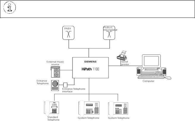
Figure 2-1 System Overview
Service Manual |
2-25 |

System Data
HiPath 1100 System Periphery
2.4HiPath 1100 System Periphery
●HiPath 1120
|
|
|
|
|
System Telephones |
|
C/D |
|
|
|
|
|
|
|
|
|
|
|
|
|
|
|
|
|
|
|
|
|
|
|
|
|
|
|||||||
|
|
|
|
|
|
|
4 x |
|
|
|
|
|
|
|
|
|
|
|
|
|
|
|
|
|
|
|
|
|
|
|
|
|||||||||
|
|
|
|
|
|
|
|
|
|
|
|
|
|
|
|
|
|
|
|
|
|
|
|
|
|
|
Service PC |
|
|
|||||||||||
|
|
|
|
|
|
|
|
|
|
|
|
|
|
|
|
|
|
|
|
|
|
|
|
|
|
|
|
|
|
|
|
|||||||||
|
|
|
|
|
|
|
|
|
|
|
|
|
Mini DIN-6 |
|
MO |
|
|
|
|
|
|
|
|
|
||||||||||||||||
|
|
|
|
|
|
|
|
|
|
|
|
|
A/B |
|
|
|
|
|
|
|
|
V.24 |
|
|
|
|
|
|
|
|
Printer |
|
|
|||||||
|
|
|
|
|
|
|
|
|
|
|
|
|
|
|
|
|
|
|
|
|
|
|
|
|
|
|
|
|
|
|
||||||||||
|
|
External analog lines |
|
|
|
|
|
2 x |
|
|
MB |
|
|
|
|
|
|
|
|
|
|
|
|
|
||||||||||||||||
|
|
|
|
|
|
|
|
|
|
|
|
|
|
|
|
|
|
|
|
|
|
|
|
|
|
|
|
|
||||||||||||
|
|
|
|
|
|
|
|
|
|
|
|
|
|
|
|
|
|
|
|
|
|
|
||||||||||||||||||
|
|
|
|
|
|
|
|
|
|
|
A/B |
|
|
|
|
|
|
|
|
|
|
|
|
|
|
|
|
|
|
|
|
|||||||||
|
|
|
|
|
|
|
|
|
|
|
|
|
|
|
|
|
|
|
|
|
|
|
|
|
|
|
|
|
|
|
|
|
|
|
|
|
||||
|
|
|
|
|
Analog extensions |
|
|
|
8 x |
|
|
|
|
|
Mini DIN-4 |
|
MO |
|
|
|
|
|
|
|
|
|
|
|
|
|||||||||||
|
|
|
|
|
|
|
|
|
|
|
|
|
|
|
|
|
|
|
|
|
|
Service PC |
|
|
|
|||||||||||||||
|
|
|
|
|
Sensor and Relay |
|
|
|
|
|
|
|
|
|
|
|
|
|
|
|
|
|
|
USB |
|
|
|
|
|
|
|
|
|
|
|
|||||
|
|
|
|
|
|
|
|
|
|
|
|
|
|
|
|
|
|
|
|
|
|
|
|
|
|
|
|
|
|
|
|
|
|
|
|
|
|
|||
|
|
|
|
|
|
|
|
|
|
|
|
|
|
|
|
ADSL |
|
|
|
|
|
|
|
|
|
|
|
|
|
|
|
|
|
|||||||
|
|
|
|
|
|
|
|
|
|
Music mod- |
|
|
|
|
|
|
|
|
|
|
|
|
|
|
|
|
|
|
||||||||||||
|
|
|
|
|
|
|
|
|
|
|
|
|
Ethernet |
|
|
HUB - 4 PC Ports |
|
|
||||||||||||||||||||||
|
|
|
|
|
Audio Device |
|
S1 / RL1 |
|
ule |
MO |
|
MO |
|
|
|
|
|
|
||||||||||||||||||||||
|
|
|
|
|
|
|
|
|
|
|
|
|
|
|
|
|
|
|
|
|
|
|
|
|
|
LAN |
|
|
|
|
|
|
|
|
|
|
|
|
|
|
|
|
|
|
|
|
|
|
|
|
|
|
|
|
|
|
|
|
|
|
|
|
|
|
|
|
|
|
|
|
|
|
|
|
|
|
|
|
|
||
|
|
|
|
|
|
|
|
|
|
|
|
|
|
|
|
|
|
|
|
|
|
|
|
|
|
|
|
|
|
|
|
|
|
|
|
|
|
|
|
|
|
|
|
|
|
|
|
|
|
|
|
|
|
|
|
|
|
|
|
|
|
|
UP0/E |
|
|
|
|
|
|
|
|
|
|
|
|
|
|
|
|
||
|
|
|
|
|
|
|
|
|
|
|
|
|
|
|
|
|
|
|
|
|
|
|
|
|
|
|
|
|
|
|
|
|
|
|
|
|
||||
|
|
|
|
|
|
|
|
|
|
|
|
|
|
|
Entrance tele- |
|
|
|
|
|
|
|
|
|
|
|
|
|
optiPoint tele- |
|
|
|||||||||
|
|
|
Internal entrance tele- |
|
|
|
|
phone interface |
|
EB |
|
|
|
|
|
|
|
|
|
|
|
|
|
|
||||||||||||||||
|
|
|
|
|
|
|
|
|
|
|
|
|
|
|
|
|
|
|
|
|
|
|
|
|||||||||||||||||
|
|
|
phone Extension |
|
|
|
|
|
|
|
MO |
|
|
|
|
|
|
|
|
|
|
|
|
|
|
|
|
|
|
|
||||||||||
|
|
|
|
|
|
|
|
|
|
|
204 and |
|
|
|
|
|
|
|
|
|
|
|
|
|
|
|
|
|
||||||||||||
|
|
|
|
|
|
|
|
|
|
|
|
|
|
|
|
|
|
|
|
|
|
|
|
|
A/B |
|
External analog lines |
|
|
|||||||||||
|
|
|
|
|
|
|
|
|
|
|
|
|
|
|
|
|
|
|
|
|
|
|
200 |
|
|
|
|
|
||||||||||||
|
|
|
|
|
|
|
|
|
|
|
|
|
|
|
|
S |
|
|
|
|
|
|
|
|
|
|
Analog extensions |
|
|
|||||||||||
|
|
|
|
|
|
|
|
|
|
ISDN |
|
|
|
0 |
|
|
|
|
|
|
|
|
|
|
|
|||||||||||||||
|
|
|
|
|
Basic Access |
|
|
|
|
|
|
|
|
|
|
|
|
|
|
|
|
|
|
|
|
|
|
|
|
|
|
|
|
|
|
|
|
|
||
|
|
|
|
S0 |
|
EB |
|
|
|
EVM |
|
|
|
|
|
|
|
|
|
|
|
|
|
|
|
|
|
|||||||||||||
|
|
|
|
|
(Public Network) |
|
|
|
|
|
|
|
|
|
|
|
|
|
|
|
|
|
|
|
|
|
|
|
|
|||||||||||
|
|
|
|
|
|
|
|
|
|
|
|
|
|
|
|
CTR-UP0/E |
|
MO |
|
|
|
|
|
|
|
|
|
|
|
|
|
|
|
|
|
|||||
|
|
|
|
|
|
|
|
|
|
|
|
|
|
|
|
|
|
|
|
|
|
|
|
|
|
|
|
|
|
|
|
|
|
|||||||
|
|
|
|
|
|
|
|
|
|
|
|
|
|
|
|
|
|
|
|
|
|
|
|
|
|
|
|
|
|
|
|
|
|
|
||||||
|
|
|
|
|
|
|
|
|
|
|
|
|
|
|
|
EB |
|
|
|
|
|
|
|
|
|
|
|
|
|
|
|
|
|
|
|
|
|
|
|
|
|
|
|
|
|
|
|
|
|
|
|
|
|
|
|
|
|
|
|
|
|
|
|
|
|
|
|
|
|
|
|
|
|
|
|
|
|
|
|
|
|
|
|
|
|
|
|
|
|
|
|
|
|
|
|
|
|
|
|
|
|
|
|
|
|
|
|
|
|
|
|
|
|
|
|
|
|
|
|
|||
Figure 2-2 |
HiPath 1120 Periphery |
|
|
|
|
|
|
|
|
|
|
|
|
|
|
|
|
|
|
|
|
|
|
|
|
|||||||||||||||
● HiPath 1150 |
|
|
|
|
|
|
|
|
|
|
|
|
|
|
|
|
|
|
|
|
|
|
|
|
|
|
|
|
|
|
|
|
||||||||
|
|
|
|
|
|
|
|
|
|
|
|
|
|
|
|
|
|
|
|
|
|
|
|
|
|
|
|
|
|
|
|
|
|
|
|
|
||||
|
|
|
|
|
System Telephones |
|
C/D |
|
|
|
|
|
|
|
|
|
|
|
|
|
|
|
|
|
|
|
|
|
|
Service PC |
|
|
||||||||
|
|
|
|
|
|
|
8 x |
|
|
|
|
|
|
|
|
|
|
|
|
|
|
|
|
|
|
|
|
|
||||||||||||
|
|
|
|
|
|
|
|
|
|
|
|
|
|
Mini DIN-6 |
|
MO |
|
|
|
|
|
|
|
|
|
|
||||||||||||||
|
|
|
|
|
|
|
|
|
|
|
|
|
|
|
|
|
|
|
|
|
|
|
|
|
|
|
|
|
Printer |
|
|
|||||||||
|
|
|
|
|
|
|
|
|
|
|
|
|
A/B |
|
|
|
|
|
|
|
|
|
|
|
V.24 |
|
|
|
|
|
|
|
|
|||||||
|
External analog lines |
|
|
|
|
|
|
|
2 x |
|
|
MB |
|
|
|
|
|
|
|
|
|
|
|
|
|
|
|
|
|
|
||||||||||
|
|
|
|
|
|
|
|
|
|
|
|
|
|
|
|
|
|
|
|
|
|
|
|
|
|
|||||||||||||||
|
|
|
|
|
|
|
|
|
|
|
|
|
|
|
|
|
|
|
|
|
|
|
|
|
|
|
|
|||||||||||||
|
|
|
|
|
|
|
|
|
|
|
A/B |
|
|
|
|
|
|
|
|
|
|
|
|
|
|
|
|
|
|
|
|
|
||||||||
|
|
|
|
|
Analog extensions |
|
|
|
10 |
|
|
|
|
|
|
|
|
|
|
|
|
|
|
|
|
|
|
|
|
|
|
|
|
|||||||
|
|
|
|
|
|
|
|
|
|
|
|
|
|
|
|
|
|
|
|
|
MO |
|
|
|
|
|
Service PC |
|
|
|||||||||||
|
|
|
|
|
|
|
|
|
|
|
|
|
|
|
|
|
|
|
|
|
Mini DIN-4 |
|
|
|
|
|
|
|||||||||||||
|
|
|
|
|
|
|
|
|
|
|
MOH |
|
|
|
|
|
|
|
|
USB |
|
|
|
|
|
|
|
|
|
|||||||||||
|
|
External music source |
|
|
Music |
|
|
|
|
|
|
|
|
|||||||||||||||||||||||||||
|
|
|
|
|
|
|
|
|
|
|
|
|
|
|
|
|
|
|
|
|
|
|
||||||||||||||||||
|
|
|
|
|
|
|
|
|
|
|
|
|
|
|
|
|
|
|
|
|
|
|
|
|
||||||||||||||||
|
|
|
|
|
|
|
|
|
|
|
|
|
|
|
|
|
|
|
|
|
|
|
|
|
|
|
|
|
|
|
|
|
|
|
||||||
|
|
|
|
|
|
|
|
|
|
|
|
|
|
|
|
|
|
|
|
|
|
|
|
|
|
|
|
|
|
|
|
|
|
|
||||||
|
|
|
|
|
|
|
|
|
|
|
|
|
|
|
|
|
|
|
|
|
|
|
ADSL |
|
|
|
|
|
|
|
|
|
|
|
|
|
HUB - 4 PC Ports |
|
|
|
|
|
|
|
|
Primary Access |
|
|
E1 |
|
TME1 |
|
|
|
Ethernet |
|
|
|
|
||||||||||||||||||||||
|
|
|
|
|
|
|
|
|
|
|
|
|
|
|
|
|
|
|||||||||||||||||||||||
|
|
|
|
|
(Public Network) |
|
|
|
|
|
|
|
EB |
|
MO |
|
|
LAN |
|
|
|
|
|
|
|
|||||||||||||||
|
|
|
|
|
|
|
|
|
|
|
|
|
|
|
|
|
|
|
|
|
|
|
|
|
|
|
|
|
|
|
|
|
|
|
|
|
|
|
|
|
|
|
|
|
|
|
|
|
|
|
|
|
|
|
|
|
Entrance |
|
UP0/E |
|
|
|
|
|
|
|
|
|
|
|
|
|
|
|
|
||||||
|
|
|
|
|
Internal entrance tele- |
|
|
|
|
|
|
|
|
|
|
|
|
|
|
optiPoint telephones |
|
|
||||||||||||||||||
|
|
|
|
|
|
|
telephone |
|
EB |
|
|
|
|
|
|
|
|
|
|
|
|
|
|
|
|
|||||||||||||||
|
|
|
|
|
phone Extension |
|
|
|
|
|
|
|
|
|
|
|
|
|
|
|
|
|
|
|
|
|
|
|
|
|||||||||||
|
|
|
|
|
|
|
|
|
|
|
|
interface |
|
|
|
|
|
|
|
|
|
|
|
|
|
|
|
|
|
|
|
|||||||||
|
|
|
|
|
|
|
|
|
|
|
|
|
|
|
|
|
010, 202, |
|
|
|
|
|
|
|
|
|
|
|
|
|
|
|
|
|||||||
|
|
|
|
|
|
|
|
|
|
|
|
|
|
|
|
|
|
|
|
|
|
|
|
|
|
|
|
|
|
|
|
|
|
|
|
|
|
|
||
|
|
|
|
|
|
|
|
|
|
|
S0 |
|
|
S |
0 |
|
|
|
206, 210, |
|
|
|
|
|
|
|
|
|
|
|
|
|
|
|
|
|||||
|
|
|
|
|
Basic Access |
|
|
|
|
|
|
|
|
A/ |
External analog lines |
|
|
|||||||||||||||||||||||
|
|
|
|
|
|
|
|
|
|
|
|
|
|
|
|
|
012, 200, |
|
|
|
||||||||||||||||||||
|
|
|
|
|
(Public Network) |
|
|
|
ISDN |
|
EB |
|
|
|
|
Analog extensions |
|
|
||||||||||||||||||||||
|
|
|
|
|
|
|
|
|
|
|
|
|
|
|
||||||||||||||||||||||||||
|
|
|
|
|
|
|
|
|
|
|
|
|
|
|
|
|
|
|
|
400, 800 |
|
|
|
|
|
|||||||||||||||
|
|
|
|
|
|
|
|
|
|
|
|
|
|
|
|
EVM |
|
|
|
|
|
|
|
|
|
|
|
|
|
|
|
|
|
|
||||||
|
|
|
|
|
|
|
|
|
|
|
|
|
|
|
|
|
|
|
|
|
|
|
|
|
|
|
|
|
|
|
|
|
|
|||||||
|
|
|
|
|
|
|
|
|
|
|
|
|
|
|
|
|
|
EB |
|
|
|
|
|
|
|
|
|
|
|
|
|
|
|
|
||||||
|
|
|
|
|
|
|
|
|
|
|
|
|
|
|
|
MO |
|
|
|
|
|
|
|
|
|
|
|
|
|
|
|
|
|
|
||||||
|
|
|
|
|
|
|
|
|
|
|
|
|
|
|
|
|
|
|
|
|
|
|
|
|
|
|
|
|
|
|
|
|
|
|
|
|||||
|
|
|
|
|
|
|
|
|
|
|
|
|
|
|
|
|
|
CTR-UP0/E |
|
|
|
|
|
|
|
|
|
|
|
|
|
|
|
|
||||||
|
|
|
|
|
|
|
|
|
|
|
|
|
|
|
|
|
|
|
|
|
|
|
|
|
|
|
|
|
|
|
|
|
|
|
|
|
|
|
||
|
|
|
|
|
|
|
|
|
|
|
|
|
|
|
|
|
|
|
|
|
|
|
|
|
|
|
|
|
|
|
|
|
|
|
|
|
|
|
||
|
|
|
|
|
|
|
|
|
|
|
|
|
|
|
|
|
|
|
|
|
|
|
EB |
|
|
|
|
|
|
|
|
|
|
|
|
|
|
|
|
|
|
|
|
|
|
|
|
|
|
|
|
|
|
|
|
|
|
|
|
|
|
|
|
|
|
|
|
|
|
|
|
|
|
|
|
|
|
|
|
|
|
Figure 2-3 HiPath 1150 Periphery
2-26 |
Service Manual |
System Data
HiPath 1100 System Periphery
●HiPath 1190
|
|
|
|
|
|
|
C/D |
|
|
|
|
|
|
|
|
|
|
|
|
|
|
|
|
|
|
|
|
Service PC |
|
System telephones |
|
|
|
|
|
8 x |
Mini DIN-6 |
|
|
|
MO |
|
|
|
|
||||||||||||
|
|
|
|
|
|
|
|
|
|
V.24 |
|
|
|
|
Printer |
|||||||||||||
|
|
|
|
|
|
MOH |
|
|
|
|
|
MB |
|
|
|
|
|
|
|
|
|
|
|
|
|
|||
|
|
|
|
|
|
|
|
|
|
|
|
|
|
|
|
|
|
|
|
|
|
|
|
|||||
|
|
|
|
|
|
Music |
|
|
|
|
|
|
|
|
|
|
|
|
|
|
||||||||
|
External music source |
|
|
|
|
Mini DIN-4 |
|
|
|
|
MO |
|
|
|
Service PC |
|||||||||||||
|
|
|
|
|
|
|
|
|
|
|
||||||||||||||||||
|
|
|
|
|
|
|
|
|
|
|
|
|
|
|
|
|
|
|
|
|
USB |
|
|
|
|
|
|
|
|
|
|
|
|
|
|
|
|
|
|
|
|
|
|
|
|
|
|
|
|
|
|
|
|
|
|
|
|
|
System |
|
|
|
|
C/D |
|
|
|
CD 16 |
|
|
|
|
|
|
|
|
|
|
|
|
|
|
|
|||
|
telephones |
|
|
|
|
|
|
|
|
MO |
|
|
ADSL |
|
|
|
|
Ethernet |
|
|
HUB - 4 PC Ports |
|||||||
|
|
|
|
|
|
|
|
|
|
|
|
|
|
|
|
|
||||||||||||
|
|
|
|
|
|
|
|
|
|
|
|
|
MO |
|
|
|
|
LAN |
|
|
|
|||||||
|
|
|
|
|
|
|
|
|
|
|
|
|
|
|
|
|
|
|
|
|
|
|
|
|||||
|
|
|
|
|
|
|
|
|
|
|
|
|
|
|
|
|
|
|
|
|
|
|
|
|||||
|
Primary Access |
|
|
E1 |
|
|
|
|
TME1 |
|
|
|
|
|
|
|
|
|
|
|
|
|
|
|||||
|
|
|
|
|
|
UP0/E |
|
|
|
|
|
|
|
|
|
|||||||||||||
|
|
|
|
|
|
|
|
|
|
|
|
optiPoint tele- |
||||||||||||||||
|
(Public Network) |
|
|
|
|
|
|
|
|
EB |
|
EB |
|
|
|
|
|
|
|
|
||||||||
|
|
|
|
|
|
|
|
|
|
|
|
|
|
phones |
||||||||||||||
|
|
|
|
|
|
|
|
|
|
|
|
|
|
|
|
|
|
|
|
|
|
|
|
|
|
|
|
|
|
|
|
|
|
|
|
|
|
|
|
|
|
|
|
|
|
|
|
|
|
|
|
|
|
|
|
|
|
|
|
|
|
|
|
|
|
|
|
|
|
|
|
|
|
|
|
|
|
|
|
|
|
|
|
|
|
|
|
|
|
|
|
|
S0 |
|
|
|
S |
0 |
|
|
|
|
|
|
|
|
|
|
|
|
|
|
|
|
|
|
|
|
|
|
|
|
|
|
|
|
|
|
|
|
|
|
|
|
|
|
|
|
|
|
||||
|
Basic Access |
|
|
|
|
|
|
|
|
|
|
010, 202, |
|
|
|
|
|
|
|
|
|
|
||||||
|
|
ISDN |
|
|
|
|
|
|
|
|
|
|
|
|
|
|
|
|
||||||||||
|
(Public Network) |
|
|
|
|
|
|
EB |
|
|
|
|
|
|
|
|
|
|
|
|||||||||
|
|
|
|
|
|
|
|
|
|
|
|
206, 210, |
|
|
|
|
|
|
|
|
|
|
||||||
|
|
|
|
|
|
|
|
|
|
|
|
|
|
|
012, 200, |
|
|
a/b |
External analog lines |
|||||||||
|
|
|
|
|
|
|
|
|
|
|
|
|
|
|
|
|
||||||||||||
|
|
|
|
|
|
|
|
|
|
|
Entrance |
|
|
|
Analog extensions |
|||||||||||||
|
Entrance tele- |
|
|
|
|
|
|
|
|
|
|
|||||||||||||||||
|
|
|
|
|
|
|
|
400, 800 |
|
|
|
|||||||||||||||||
|
phone Extension |
|
|
|
|
|
|
|
telephone |
|
|
|
|
|
|
|
|
|
|
|||||||||
|
|
|
|
|
|
|
|
|
EB |
|
|
|
|
|
|
|
|
|
||||||||||
|
|
|
|
|
|
|
|
interface |
|
|
|
|
|
|
|
|
|
|
||||||||||
|
|
|
|
|
|
|
|
|
|
|
|
|
|
|
|
|
|
|
|
|
||||||||
|
|
|
|
|
|
|
|
|
|
|
|
|
|
|
|
|
|
|
|
|
|
|
|
|
||||
|
|
|
|
|
|
|
|
|
|
|
|
|
|
|
|
|
|
|
|
|
|
|
|
|
||||
|
|
|
|
|
|
|
|
|
|
|
EVM |
|
CTR-UP0/E |
|
|
|
|
|
|
|
|
|
||||||
|
|
|
|
|
|
|
|
|
|
|
|
MO |
|
EB |
|
|
|
|
|
|
|
|
|
|||||
|
|
|
|
|
|
|
|
|
|
|
|
|
|
|
|
|
|
|
|
|
|
|
|
|
|
|
|
|
|
|
|
|
|
|
|
|
|
|
|
|
|
|
|
|
|
|
|
|
|
|
|
|
|
|
|
|
|
|
|
|
|
|
|
|
|
|
|
|
|
|
|
|
|
|||||||||||||
Figure 2-4 |
HiPath 1190 Periphery |
|
|
|
|
|
|
|
|
|
|
|
|
|
|
|||||||||||||
Service Manual |
2-27 |
System Data
System expansion limitations
2.5System expansion limitations
During system installation (see “Installing modules” on page 4-136) please consider characteristics, recommendations and limitations of the modules that will comprise the final set. We therefore recommend that you read this chapter carefully, where you will find the maximum capacities of each module and how it interacts with the other components.
Basic configuration: |
HiPath 1120 |
HiPath 1150 |
HiPath 1190 |
|
|
|
|
External analog lines |
2 |
|
0 |
|
|
|
|
Analog extensions |
8 |
10 |
|
|
|
|
|
System telephone |
4 |
8 |
|
interface (KS)* |
|
|
|
Expansion modules: |
|
|
|
|
|
|
|
EB 010 (10 extensions) |
0 |
4 |
14 |
|
|
|
|
EB 012 (12 extensions) |
0 |
3 |
11 |
|
|
|
|
EB 202 (2 external lines and 2 extensions) |
0 |
4 |
16 |
|
|
|
|
EB 204 (2 external lines and 4 extensions) |
2 |
0 |
|
|
|
|
|
EB 206 (2 external lines and 6 extensions) |
0 |
4 |
16 |
|
|
|
|
EB 210 (2 external lines and 10 |
0 |
4 |
11 |
extensions) |
|
|
|
|
|
|
|
EB 200 (2 external lines) |
2 |
4 |
16 |
|
|
|
|
EB 400 (4 external lines) |
0 |
3 |
10 |
|
|
|
|
EB 800 (8 external lines) |
0 |
1 |
5 |
|
|
|
|
S0 module |
1 |
|
2 |
TME1 module |
0 |
1 |
2 |
|
|
|
|
UP0/E module (optiPoint): |
1 |
1 or 2 |
|
|
|
(see “CTR-UP0/E module” on |
|
|
|
page 3-77) |
|
|
|
|
|
CD 16 module (KS) |
0 |
|
1 |
|
|
|
|
Optional modules:** |
|
|
|
LAN interface modules |
1 |
|
|
(ADSL, SLIMC, SADSLIM, LIMC or |
|
|
|
ADSLIM) |
|
|
|
|
|
|
|
EVM module |
1 |
|
|
|
|
|
|
Music module |
1 |
on board |
|
|
|
|
|
TFE entrance telephone interface |
20 |
|
|
|
|
|
|
Total System Capacity:***: |
|
|
|
2-28 |
|
|
Service Manual |
System Data
System expansion limitations
Extension (analog + digital) |
23 |
89 |
143 |
|
|
|
|
System Telephones (KS + optiPoint) |
4 KS |
8 KS |
8 KS |
(see “CTR-UP0/E module” on page 3-77) |
or |
+ |
+ |
8 optiPoint |
16 optiPoint |
16 optiPoint |
|
|
(4 master + 4 |
(8 master + 8 |
(8 master + 8 |
|
slave) |
slave) |
slave) |
|
|
|
or |
|
|
|
24 KS (CD 16 |
|
|
|
module) |
|
|
|
|
Digital line with TME1/Digital line with S0 |
0/2 |
30/10 |
45/20 |
External analog lines without TME1 or S0 |
6 |
16 |
40 |
modules |
|
|
|
Digital line (TME1) + analog line/digital line |
0/8 |
32/16 |
45/44 |
(S0)+ analog line |
|
|
|
|
|
|
|
*Each system telephone (KS) that is connected occupies one analog telephone slot.
**S0 and TME1 modules cannot be used simultaneously.
LAN and TME1 interface modules can be used simultaneously in HiPath 1150/1190.
-HiPath 1120 : ADSL modules, SLIMC and SADSLIM module
-HiPath 1150/1190 :ADSL modules, SLIMC and SADSLIM module
***When the maximum capacity for external lines is exceeded due to the installation of EB, S0 or TME1 modules, the system disables external analog lines. Extension slots, however, continue to operate as usual.
Example 1: HiPath 1150
-slot 0, MB 210,
-slot 1, EB 210,
-slot 3 TME1 - 30 digital lines
EB 210 external lines will not work, but extensions will. Since the system allows for a maximum number of 32 lines, we cannot have any additional analog line.
Example 2: HiPath 1150
-slot 0, MB 210
-slot 3 TME1 = 30 digital lines
In this case, there are 32 external lines at most available on the system. This means there is no room for an additional EB module with an external analog line.
30 CAS/S2 digital lines + 2 MB external analog lines = 32 external lines.
If an EB 200 was installed in slot 1 or slot 2 the module would not be operable, since it would exceed the system’s maximum capacity for external lines.
Example 3: HiPath 1150
-slot 0, MB 210
-slot 3 TME1 = 10 digital lines
(WARNING: Deactivate digital line for the TME1 module and program unused digital lines on the switch as unavailable (turn the switch off then on).
Overall, there are 12 external lines on the system. This means there are 4 additional external lines available before reaching the maximum capacity of 16 external lines.
An additional EB 400 could be used in slot 1 or slot 2.
If an EB 800 were installed on the switch, the entire module would be inoperable since it would exceed the system’s maximum capacity for external lines.
Table 2-1 Specific limitations to system expansion
Service Manual |
2-29 |
System Data
System expansion limitations
2.5.1Considerations for digital lines
HiPath 1120
Maximum number of external lines allowed is 16 (S0 digital lines + external analog lines)
|
|
|
|
|
Settings |
|
External analog line |
S0 module digital line |
Total |
MB + 1 EB 200 |
|
4 |
0 |
4 |
MB + 1 S0-2 |
|
2 |
4 |
6 |
MB + 1 S0-2 + 1 EB 200 |
4 |
4 |
8 |
|
Table 2-2 |
Considerations on S0 digital lines on the HiPath 1120 |
|
||
HiPath 1150
Maximum number of external lines allowed is 16 (S0 digital lines + external analog lines)
2-30 |
Service Manual |
Loading...