


FishFinder L470
Instruction Manual
Raymarine

Contents
1
2
3
Echo sounding – How it works |
(inside front cover) |
FishFinder L470 – Features and functions i |
|
For information and service ii |
|
Introduction 1 |
|
About the FishFinder L470 1 |
|
System Components |
2 |
Standard Equipment |
2 |
Standard Transducers |
2 |
Optional Accessories |
2 |
Installation 4
About the Transducer 4 |
|
|
|
|
Selecting the Correct Type of Transducer 5 |
|
|||
Assembling the Transducer Bracket |
6 |
|
|
|
Positioning the Transom-Mount Transducer |
6 |
|
||
Mounting the Transom-Mount Transducer |
9 |
|
||
Mounting the Optional Sidelooker Transducer - |
||||
Transom-Mount Installation |
10 |
|
|
|
Installation Notes – Thru-Hull Transducer |
11 |
|
||
Installation Notes – In-Hull Transducer 12 |
|
|
||
Installation Notes – Trolling Motor Transducers |
13 |
|||
Installation Notes – |
|
|
|
|
Transducer for Speed and Temperature Only |
14 |
|||
EMC Installation Guidelines |
14 |
|
|
|
Mounting the Display Unit – Standard Mount |
16 |
|||
Dismounting the Display Unit |
16 |
|
|
|
Mounting the Display Unit – Flush Mount |
18 |
|
||
Installing the Transducer Cable 19 |
|
|
|
|
Installing the Transducer Cable – Sidelooker Option 21 |
||||
Installing the Transducer Cable – |
|
|
|
|
Separate Speed and Temperature Sensors |
21 |
|||
Making the DC Power Connections |
22 |
|
|
|
Calibrating the Sensors 24 |
|
|
|
|
Operating Instructions 26
Controls on Display Panel 26 Turning the Power On and Off 28 Setup Memory 28
iv

Lamp/Contrast Menu 29
Operating Pages 30
FishFinder Page 32
Choosing a Frequency 37
Fish Indications 38
Bottom Indications 39
Window Page 41
Sidelooker Page 43
Digital Page 47
Performance Modes 50
Zoom Mode 50
A-Scope (Bottom Coverage) Mode 52
Bottom Lock Mode 54
4 Setup Instructions 56
The Setup Menu 56
Range Setting 57
Sensitivity Setting 58
Chart Speed Setting 60
Frequency Setting 61
Resetting the Log 63
System Setup Menu |
64 |
Deep Alarm |
68 |
||
Simulator |
65 |
|
|||
Language |
65 |
|
Fish Alarm |
68 |
|
Fish Symbols |
65 |
Buzzer |
69 |
|
|
White Line |
65 |
|
Depth Units |
70 |
|
VRM 66 |
|
|
Speed Units |
70 |
|
Sidelooker |
66 |
|
Temp Units |
70 |
|
Speed Cal |
66 |
|
Speed |
70 |
|
Temp Cal 67 |
Log |
70 |
|
Depth Digits 67 |
Temp |
70 |
|
Shallow Alarm 67 |
|
|
|
Setup Menus for Zoom Mode |
71 |
|
|
Zoom Select Menu 71 |
|
|
|
Zoom Screen Split/Full Menu Item |
72 |
||
Setup Menus for Bottom Lock Mode |
73 |
||
Bottom Lock Range Menu Item |
73 |
||
Bottom Lock Split/Full Menu Item |
74 |
||
Setup Menu for Window Page |
75 |
|
|
Resetting from the Digital Page 76 |
|
|
|
v

5
6
vi
Setup Instructions for Sidelooker |
76 |
|
Sidelooker Range Menu Item 77 |
||
Sidelooker Sensitivity Menu Item |
78 |
|
Sidelooker Chart Speed Menu Item 78 |
||
Sidelooker View Menu item |
79 |
|
Combining Displays 80 |
|
|
Resetting the Unit to Factory Defaults |
81 |
|
Default Settings 82 |
|
|
Maintenance and Troubleshooting 83
Cleaning Instructions 83 Troubleshooting Suggestions 83 Servicing a Thru-Hull Transducer 87 How to Contact Raymarine 87
Specifications 91
General Information 91
FishFinder Functions 92
Connector Diagrams 93
Glossary of Terms 94

List of Figures
Figure |
|
Page |
|||
|
Unit in Use |
Inside front cover |
|
|
|
|
Front Panel |
|
i |
|
|
1-1 |
Typical Installation |
|
1 |
|
|
2-1 |
Transducer Types |
|
5 |
|
|
2-2 |
Assembling the Transducer Bracket |
|
6 |
|
|
2-3 |
Transducer Mounted on Transom |
|
7 |
|
|
2-4 |
Transducer Bracket, Side View |
|
7 |
|
|
2-5 |
Correct Mounting Position |
|
8 |
|
|
2-6 |
Mounting the Transducer |
|
8 |
|
|
2-7 |
Installing the Sidelooker Transducer |
|
10 |
|
|
2-8 |
Installing the Sidelooker Transducer |
|
|
|
|
|
on a Trolling Motor |
|
13 |
|
|
2-9 |
Suppression Ferrites |
|
15 |
|
|
2-10 |
Installation on Bracket |
|
16 |
|
|
2-11 |
Dimensions |
|
17 |
|
|
2-12 |
Flush-Mount Installation |
|
18 |
|
|
2-13 |
Disassembling from Bracket |
|
19 |
|
|
2-14 |
Installing Cable on Transom |
|
20 |
|
|
2-15 |
Cable for Sidelooker Transducer |
|
21 |
|
|
2-16 Cable for Speed and Temperature Sensor |
22 |
|
|
||
2-17 DC Power Connections |
|
23 |
|
|
|
3-1 |
Display Panel |
|
26 |
|
|
3-2 |
Lamp/Contrast Menu |
|
29 |
|
|
3-3 |
Operating Pages |
|
31 |
|
|
3-4 |
FishFinder Page |
|
32 |
|
|
3-5 |
Fish Indications |
|
38 |
|
|
3-6 |
Bottom Conditions |
|
40 |
|
|
3-7 |
Window Page |
|
41 |
|
|
3-8 |
Options for Window Page |
|
42 |
|
|
3-9 |
Sidelooker Feature |
|
43 |
|
|
3-10 |
Sidelooker Page |
|
44 |
|
|
3-11 |
Digital Page |
|
47 |
|
|
3-12 |
Performance Modes |
|
49 |
|
|
3-13 |
Zoom Mode |
|
50 |
|
|
3-14 |
A-Scope Mode |
|
52 |
|
|
3-15 |
Bottom Lock Mode |
|
54 |
|
|
4-1 |
Setup Menus |
|
56 |
|
|
4-2 |
Range Menu Item |
|
57 |
|
|
4-3 |
Sensitivity Menu Item |
|
58 |
|
|
4-4 |
Changing the Chart Speed Setting |
|
60 |
|
|
4-5 |
Chart Speed Menu Item |
|
61 |
|
|
vii

4-6 |
Frequency Menu Item |
61 |
|
4-7 |
Log Reset Menu Item |
63 |
|
4-8 |
Reaching the System Setup Menu |
64 |
|
4-9 |
System Setup Menu |
64 |
|
4-10 Zoom Select Menu Item |
71 |
|
|
4-11 Zoom Screen Split/Full Menu Item |
72 |
|
|
4-12 Bottom Lock Range Menu Item |
73 |
|
|
4-13 Bottom Lock Split/Full Menu Item |
74 |
|
|
4-14 |
Digital Setup Menu Item |
75 |
|
4-15 Sidelooker Range Menu item |
77 |
|
|
4-16 Sidelooker Sensitivity Menu Item |
78 |
|
|
4-17 Sidelooker Chart Speed Menu Item |
78 |
|
|
4-18 |
Sidelooker View Menu Item |
79 |
|
4-19 Split FishFinder Page with A-Scope Mode |
80 |
|
|
4-20 |
Window Page with Option G Selected |
|
|
|
and Zoom Enabled |
81 |
|
5-1 |
Sample Mailing Label |
89 |
|
6-1 |
Connector Diagrams |
93 |
|
viii
1 – Introduction
About the FishFinder L470
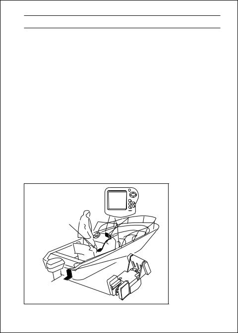
The FishFinder L470 is a system that uses sound waves (“sonar”) to detect fish and show the bottom of a lake or sea. The system includes a transducer and a display unit, connected by a cable. The transducer sends high-frequency sound waves down into the water. These sounds strike fish, the bottom, or other objects in the water, and return as echoes. The FishFinder then interprets these echoes and presents a display.
The FishFinder L470 can handle many different jobs:
•detect the presence of fish below the boat
•trigger an alarm when fish are found
•measure the depth of the water
•set alarms for minimum and maximum depth
•show the shape of the bottom
•determine whether the seabed is hard or soft
•measure the speed of the boat and the distance traveled
•show the water temperature
We are sure you will find the FishFinder L470 to be one of the most useful devices on your boat.
|
Raymarine |
FishFinder L470 |
|
Display Unit |
|
|
L470 |
Optional Thru Hull |
|
Transducer |
|
Transducer mounted |
Fig. 1-1 |
in quick release |
|
transom bracket |
Typical Installation |
|
|
Introduction |
1 |

System Components
The FishFinder L470 consists of a compact display unit connected to a transducer. The transducer is attached to the boat and extends into the water.
Standard Equipment
When you unpack your FishFinder L470, you should find the following standard equipment in the carton. If any items are missing, please notify your Raymarine dealer immediately, or contact the Customer Service Department at Raymarine at 1-800-539-5539, ext. 2333. Please provide the serial number of the FishFinder when reporting any missing items.
Description |
Part No. |
FishFinder L470 display unit |
E61013 |
|
|
Quick-release swivel-mount bracket |
|
(with mounting hardware) |
G623996-1 |
|
|
DC power cable |
M99-146 |
|
|
Instruction manual |
G627172-3 |
|
|
Four #10 x 3/4” ss mounting screws |
— |
|
|
Standard Transducers
Depending on which model of the L470 you have purchased, the box will include one of the transducers listed below:
Description |
Part No. |
Transom-mount transducer (with speed |
|
and temperature sensors, including |
|
mounting bracket and hardware) |
M78898 |
|
|
Bronze thru-hull transducer (with |
|
speed and temperature sensors) |
M78923 |
|
|
Optional Accessories
Optional accessories and parts can be purchased directly from Raymarine. For prices and ordering information, please call the Parts Department at (800) 539-5539 ext. 2333.
2 |
Introduction |

Description |
Part No. |
Sidelooker transom-mount transducer |
M78930 |
|
|
Sidelooker transducer for trolling motor |
|
mounting. Companion with M78928 |
|
downlooker depth/temp transducer, |
|
with 12 ft. (3.6 m) cable and hardware |
M78929 |
|
|
Extension cable, 5 pin (15 ft., 4.5 m) |
M99-140 |
|
|
Extension cable, 9 pin (15 ft., 4.5 m) |
M99-139 |
|
|
Flush-mounting kit (with hardware and |
|
mounting template) |
M99-138 |
|
|
Fairing block for M78923 thru-hull |
|
transducer (Lexan® ) |
M99-142 |
Low profile plastic thru-hull transducer |
|
(Valox® plastic, sensor for depth only) |
M78922 |
Bronze thru-hull transducer |
|
(sensor for depth only) |
M78921 |
In-hull/trolling motor transducer (for installation in fiberglass hull only, or mounting on trolling motor,
including hardware for either installation |
|
and 20’ or 6m cable) |
M78928 |
|
|
Angled in-hull transducer (for installation |
|
in fiberglass hull only, where deadrise |
|
angle is 10° to 22°) |
M78946 |
Plastic thru-hull transducer (Valox® plastic, with speed and temperature sensors, used with depth-
only transducers M78922, M78928, M78946) |
M78937 |
Transom-mount speed and temperature |
|
sensor (used with depth-only transducers |
|
M78922, M78928, M78946) |
M78936 |
|
|
Replacement transom transducer |
|
mounting bracket kit |
M99-148 |
|
|
Transducer switch box (select between two L470 |
|
FishFinder displays, using one transducer) |
M99-136 |
|
|
Replacement paddle wheel kit (for transom- |
|
mount transducer) |
M99-143 |
|
|
Replacement paddle wheel kit |
|
(for thru-hull transducer) |
D234 |
|
|
Replacement paddle wheel kit |
|
(for bronze thru-hull transducer) |
D144 |
|
|
Introduction |
3 |

2 – Installation
The installation process has four parts:
•Mounting the transducer
•Mounting the display unit
•Connecting the cables for the transducer and power supply
•Calibrating the display unit
About the Transducer
Several different kinds of transducers can be used with this unit. The transommount style, used most often, and in-hull types are shown in Fig. 2-1.
Besides measuring depth, the transducers have two other sensors: a paddle wheel which detects the speed of the boat, and a sensor for the water temperature. An optional transducer, the Sidelooker, detects objects by looking out to the sides of the boat.
Since the transducer is very important to the operation of the FishFinder, it is vital that the transducer be mounted correctly. The transducer will give the most reliable readings if it looks into water which is smooth and undisturbed. If you place the transducer so bubbles or turbulence flow across the face of the unit, the system may give inaccurate readings.
There are three important rules when mounting any type of transducer:
•The transducer should be continuously covered by water when the boat is moving. (If the transducer is mounted near the side of the boat, it may be exposed when the boat is turning.)
•The transducer should be placed where turbulence or bubbles will not pass directly over the face of the unit. Don’t place the transducer behind any running strakes, intakes, or thru-hull fittings which create turbulence.
•The transducer should be mounted where it will not be affected by the wash from the propeller(s).
4 |
Installation |
|
|
M78898 |
M78923 |
M99-142 |
Transom-mount |
Thru-hull |
Fairing for |
transducer |
transducer |
thru-hull transducer |
M78946 |
M78930 |
M78929 |
|
In-hull |
Sidelooker |
Sidelooker |
Fig. 2-1 |
transducer |
transducer for |
transducer for |
|
|
transom mount |
trolling motor |
Transducer |
|
|
|
|
|
|
|
Types |
Selecting the Correct Type of Transducer
Before you begin the installation, double-check to be sure you have the correct type of transducer. Each kind of transducer is designed for a particular type of use. In this manual we will include detailed mounting instructions for the transom-mount transducer. We will also include some general information on the other types. For detailed information on these other transducers, see the instructions which are packaged with the unit.
Use a transom-mount transducer if –
. . . your boat has an outboard or inboard-outboard engine(s), and if you’re planning to use the Sidelooker option. This type of transducer must be mounted ahead of or beside the propeller(s). Do not use this type of transducer for a boat with a straight-shaft inboard engine.
Use a thru-hull transducer if –
. . . your boat has a straight-shaft inboard engine. This type of transducer is installed in a hole drilled through the hull.
Use an in-hull transducer if –
. . . you have a high-speed boat or if, for some reason, you cannot use a transom-mount or thru-hull transducer. The hull may be no more than 1" thick.
Installation |
5 |
Use a trolling motor transducer if –
. . . you want to attach the transducer to a trolling motor. (Not recommended for deep water operations.)
Use a Sidelooker transducer –
. . . for searching for fish or structure on either side of the boat. This type of transducer is attached to the bracket of the transom-mount transducer, or to the shaft of the trolling motor.
Assembling the Transducer Bracket
Fit together the two parts of the transducer bracket as shown in Fig. 2-2. When the installation is complete, the parts snap together as shown.
LIKE THIS! |
NOT THIS! |
Attach the |
Bracket is installed |
two parts |
upside down |
Lower the transducer and snap in the release clip
Fig. 2-2
Assembling
the Transducer
Bracket
Positioning the Transom-Mount Transducer
Begin by finding the best location for the mounting bracket. Here are the rules:
•If your boat has one propeller (outboard or inboard-outboard), mount the transducer about 18" (455 mm) to the side of the centerline of the boat. See Fig. 2-3. Choose the side that is on the downstroke of the propeller. (This is usually the starboard side of the boat.) This will reduce interference caused by air bubbles.
•If the propeller can be turned to steer the boat, allow at least 2" (50 mm) beyond the swing radius of the propeller. This will prevent the propeller from damaging the transducer when it is turned. After installation, check the clearance by turning the wheel so the propeller swings toward the transducer. There should always be a 2" (50 mm) clearance.
6 |
Installation |
|
|
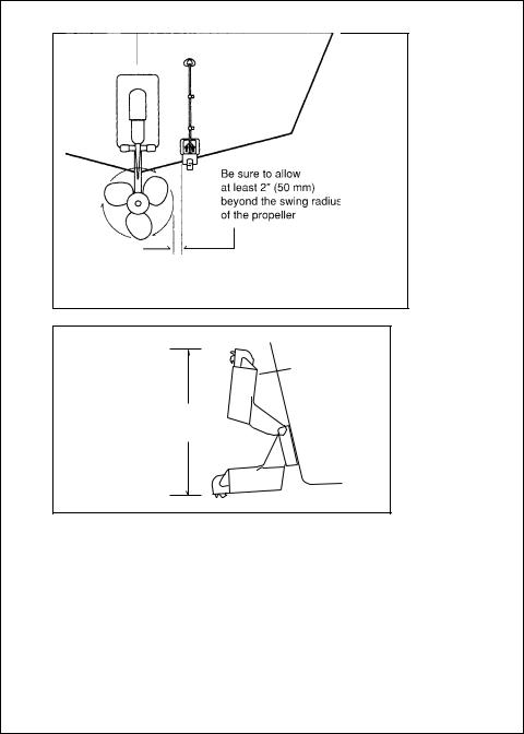
Allow a clearance of at least 10 inches (254 mm)
10" (254 mm)
Fig. 2-3
Transducer
Mounted on
Transom
Transducer in released position
Fig. 2-4
Transducer
Bracket,
Side View
•If your boat has twin propellers (outboard or inboard-outboard), place the transducer near the centerline of the boat.
•Do not mount the transducer behind any hull fittings, intakes, or other parts which extend from the hull. These may cause turbulence or air bubbles.
•The bracket has a quick-release mechanism. This may reduce damage by allowing the transducer to flip up if it hits any debris or the bottom. See Fig. 2-4. Allow enough clearance above the transducer so that it can swing upward completely. This is about 10" (254 mm)
Installation |
7 |
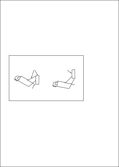
Average transom angle– |
Vertical transom – |
Sloping transom– |
no wedge necessary |
place wedge this way |
place wedge this way |
2 to 5 |
2 to 5 |
2 to 5 |
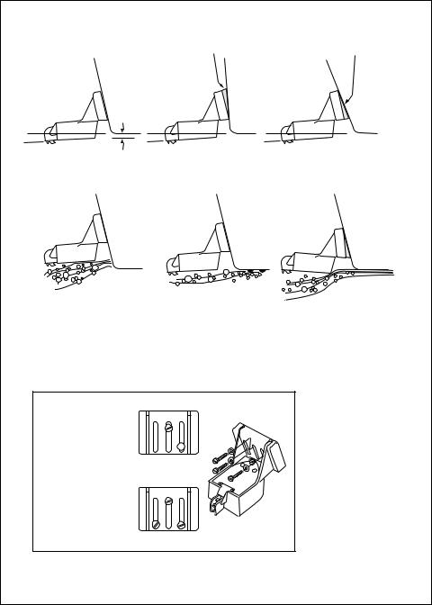
For fiberglass hull – 1/8" to 1/4" (3.2 to 6 mm)
For aluminum hull – 1/4" to 3/8" (6 to 9 mm)
No! |
No! |
No! |
The bow of the transducer |
Rivets on the hull are |
is above the bottom of the |
creating bubbles. |
transom, creating |
Lower the transducer |
cavitation. |
a bit. |
1 2 3
Insert screws 1 and 3 1/4" from the bottom of
slots, and screw 2 1/4" from the top of the
slot to allow room for 
 adjustment. Correct
alignment
If screws are inserted this way, it won’t be possible to make the height adjustment.
Incorrect alignment
8
The rear of the transducer is too high, creating cavitation.
Fig. 2-5
Correct Mounting
Position
Fig. 2-6
Mounting
the Transducer
Installation

measured from the bottom of the transom.
•If considering the Sidelooker option, look for a mounting location where the Sidelooker array will not be blocked by the engine housing or other mounted hardware.
•If the boat will be carried on a trailer, be sure the transducer will not hit any rollers, bunks or fittings on the trailer.
Mounting the Transom-Mount Transducer
1.On a boat with a fiberglass hull, the leading edge of the transducer should extend 1/8" (3.2 mm) to 1/4" (6 mm) below the bottom edge of the hull. See Fig. 2-5. On an aluminum hull, the transducer should extend a bit more – 1/4" (6 mm) to 3/8" (9 mm). If the boat will be operated at high speeds, the transducer may be mounted closer to the centerline of the hull.
2.The lower surface of the transducer should tilt down toward the rear at a slight angle (2° to 5°). The mounting bracket includes a wedge. Depending on the angle of the transom on your boat, you may need this wedge to get the correct angle for the bottom of the transducer.
3.Looking at the rear of the boat, be sure the bracket is vertical (perpendicular to the water line).
4.Hold the bracket (and the wedge, if used) against the transom and trace the positions of the screw slots.
5.Remove the bracket. See Fig. 2-6. The screws in the outer slots should be placed about 1/4" (6 mm) up from the bottom of each slot. The screw in the center slot should be placed 1/4” (6 mm) down from the top. (This will allow you to adjust the bracket up or down a bit.) Drill pilot holes 3/4" (19.1 mm) deep. Use a 9/64" (3.6 mm) drill bit. To prevent drilling too deeply, wrap masking tape around the drill bit about 7/8" (22 mm) from the tip. Drill in only as far as the tape marker.
If you are attaching the bracket to a fiberglass hull, you can minimize any surface cracking of the gel coat. Before drilling each pilot hole, drill a shallow hole (chamfer) at each location about 1/16" (1.5 mm) deep. Use a 1/4" (6 mm) drill bit.
6.Attach the bracket to the hull using the panhead screws with flat washers. Before you tighten the screws, apply a good-quality marine sealant to the pilot holes. This will protect the hull from water penetration. Do not tighten the screws completely yet.
Installation |
9 |

7.Move the bracket up or down so that the leading edge of the transducer has the clearance shown in Fig. 2-5.
8.Once the bracket is in the correct position, you can tighten the screws.
Mounting the Optional Sidelooker Transducer -
Transom-Mount Installation
1.The Sidelooker transducer allows the display unit to check the water to either side of the boat. This is helpful when you are looking for fish or structure near banks, or under docks or piers.
2.The M78930 Sidelooker transducer is attached to the same mounting bracket used with the transom-mount transducer. See Fig. 2-7. Begin by installing the transom-mount bracket as described earlier.
Fig. 2-7
Installing the
Sidelooker
Transducer
3.Remove the two screws and the bracket covering the paddle wheels.
4.Attach the Sidelooker transducer to the top of the transom mounting bracket. Use the four panhead screws supplied. The fit should be snug, but do not overtighten the screws.
5.Run the Sidelooker cable beside the depth cable for the transommount transducer.
10 |
Installation |
|
|

Installation Notes – Thru-Hull Transducer
Detailed instructions for this installation will be included with the transducer. In this section, we will note just a few important points.
1.Earlier we listed three general rules for placing transducers. All of these rules apply when you are mounting a thru-hull transducer. Here are some other rules for selecting the best mounting location: For planing hulls – Install in the flat planing area near the stern. Always install forward of the propeller(s) and shaft(s).
For small displacement hulls – Install near the centerline of the hull and 1/3 of the way forward from the stern. Always install forward of the propeller(s) and shaft(s).
For large displacement hulls – Install near the centerline of the hull and 1/3 of the way aft from the bow. Always install forward of the propeller(s) and shaft(s).
For sailboats – Install forward of the leading edge of the keel, to one side and near the centerline of the hull.
2.Choose a location where you can easily reach the transducer from inside the boat. This will allow you to service the unit. Allow at least 6" (152 mm) of headroom above the transducer.
3.When choosing a mounting location, drill a small pilot hole (1/8" or 3.2 mm) from the inside of the hull. Before you drill the hole, be sure you will be able to reach the large nut on the top of the unit, and that there will be enough clearance for the cable. If there is a strake or other feature on the hull, drill from the outside of the hull instead. (This small hole can be filled easily if the mounting location is not suitable.)
4.The position of the transducer is especially critical on high speed boats (capable of more than 20 knots). Check the locations of the transducers on similar boats before installing the transducer in your own boat. Choose the location which will offer the best performance.
5.If the bottom of the hull at the mounting location is flat, you can mount the transducer directly through the hull. If the hull rises at an angle (the “deadrise angle”) of more than 10°, you must include a mounting block or “fairing.” The transducer must be mounted in a vertical position. Attach the fairing block to the hull as firmly as possible. This fairing block must be able to resist the drag of the water against the hull, and must also be completely waterproof.
Installation |
11 |

6.If the hull of the boat has a core-type hull, you will need to follow some special mounting procedures. The core material must be protected from any water which may leak from the inside of the boat. (If the core material is allowed to remain wet, it may rot and weaken the hull.)
7.When working with the transducer, support it by holding the body of the unit or the rings. Do not hang the transducer from the cable.
8.It is very important to seal the opening around the transducer using a high-quality marine sealant suitable for underwater use. After installation, do not leave your boat in the water for any amount of time without checking for leaks.
Installation Notes – In-Hull Transducer
Detailed instructions for this installation will be included with the transducer. In this section, we will note just a few important points.
1.Choose the best mounting location:
For outboard powerboats – Install as far aft as possible
For inboard/outboard powerboats – Install close to the engine(s)
For inboard powerboats – Install forward of the propeller(s) and shaft(s)
For sailboats – Install near the centerline of the hull and forward of the leading edge of the keel
2.An in-hull transducer may only be installed in a fiberglass hull which is no more than 1" (25 mm) thick. The in-hull transducer may not be installed in wood or aluminum hulls.
3.Use the standard in-hull transducer if it will be installed in a flat part of the hull, or a section with no more than 10° of deadrise. Use the angled in-hull transducer if the mounting location has up to a 22° of deadrise.
4.Do not try to compensate for the angle of the hull by fairing the epoxy adhesive on the face of the transducer.
5.Use the epoxy supplied with the in-hull transducer, or an equivalent epoxy glue. Do not use any other type of adhesive, including silicone or RTV adhesive.
12 |
Installation |
|
|

Installation Notes – Trolling Motor Transducers
Both Downlooker and Sidelooker transducers may be installed on a trolling motor. See Fig. 2-8.
Fig. 2-8
Installing the
Sidelooker
Transducer on a
Trolling Motor
Detailed instructions for these installations will be included with the transducer(s). The Downlooker transducer is mounted on the horizontal gear case of the motor. The Sidelooker transducer is attached to the vertical support tube. These installations are simple, but it is important to keep these points in mind:
1.Keep the Sidelooker transducer fully submerged. The transducer will only produce an image if it is immersed in water.
2.Keep the Sidelooker transducer clear of weeds or debris.
3.When the position of the trolling motor is changed, the field of view of the Sidelooker also changes. The Sidelooker can be aimed at interesting echoes, but can also be positioned so that it is looking back at the hull. Be aware of the position of the Sidelooker transducer.
Installation |
13 |

Installation Notes – Transducer for Speed and Temperature Only
This type of transducer may be used with a thru-hull transducer which reads depth only. The speed/temperature transducer is attached to the transom of the boat. Detailed instructions for this installation will be included with the transducer. The cable for this transducer uses a “Y” connector. See the notes on “Installing the Transducer Cable.”
EMC Installation Guidelines
When different types of marine electronic equipment are mounted closely together in a tight space, they may interfere with each other. The design and manufacture of this unit follow industry standards for “Electromagnetic Compatibility” (EMC). However, it is important to install the unit correctly to ensure the best possible performance. Below is a list of some of the factors which could affect the operation of the product. Some of these factors may affect the way you install the FishFinder and the wiring cables.
•Place the display unit and the power and signal cables at least 3 ft. (1m) from any equipment transmitting radio signals, or any cables carrying radio signals. This includes VHF radios, cables and antennas. In the case of SSB radios, the distance should be increased to 7 ft. (2m).
•Allow a space of at least 7 ft. (2m) from the path of a radar beam. Normally, a radar beam will spread about 20° above and below the radiating element.
•The power for the display unit should be supplied from a different battery than the one used to start the engine. If the voltage to the FishFinder unit drops below +10.8 V DC, this could cause the unit to reset. This will not damage the equipment, but it may cause the loss of some information, and it can change the operating mode.
Avoid running the FishFinder power wires near the power wiring for any radar, radio, or Loran-C units. If possible, wire the FishFinder power wires to a separate circuit breaker.
•If the transducer cable runs near another electrical wire, it may pick up electrical interference or “noise.” To reduce this, try to keep the
14 |
Installation |
|
|
transducer cable separated as far as possible from all other wires. This is especially important with wiring for the boat’s ignition, alternator, or tachometer. It is also helpful to keep the transducer cable away from the FishFinder power cable. If it is necessary to run the transducer cable across any wires, make the crossing at a right angle.
•Use only genuine Raymarine cables. During the installation, do not cut the transducer cable or remove the connector. Do not try to shorten or splice the cable. The transducer cable includes several wires, along with shielding and insulation. If the cable is cut, it cannot be repaired. (Cutting the cable will also void the warranty.) During installation, if you need to drill any holes for the cable, they must be large enough to accept the connector. This will allow you to make the installation without cutting the wire.
•A “suppression ferrite” may be attached to one of the cables. See Fig. 2-9. If you must remove the ferrite during installation, be sure to reassemble it in the same position.
Fig. 2-9 |
Suppression |
Ferrites |
Installation |
15 |
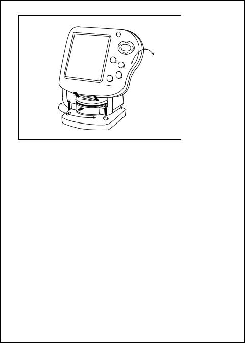
To release the display from the base, press on the right and left sides until you hear the clicks. Slide the display out
of the bracket.
The display can be turned from side to side.
Raymarine
PWR
SETUP
 CLEAR ZOOM
A-SCP BOT LOCK
FISHFINDER
L470
The angle of the display
can be changed.
Fig. 2-10
Installation on Bracket
Mounting the Display Unit – Standard Mount
You may mount the display unit on any flat surface using the bracket supplied. See Fig. 2-10. (There is also an optional kit which allows you to flush-mount the display in a flat panel or dashboard). Follow these instructions if you are using the standard mounting bracket:
1.The “LCD” type display used on this unit is easier to see from certain angles. Before selecting a permanent mounting location, make temporary power connections and turn on the unit. This will allow you to test the visibility of the display from several different angles.
2.Remove the display unit from the bracket by pressing on the large button in the center of the bracket. See Fig. 2-10.
3.Mount the base of the bracket using the supplied screws.
4.Slide the display unit back into the bracket.
5.Adjust the display unit for the best viewing angle. You can turn the display from side to side, and tilt it up or down.
Dismounting the Display Unit
See Fig. 2-10. To release the display from the bracket, press and hold down the left and right sides. You will hear an audible “click,” and the bracket will slide out.
16 |
Installation |
|
|

Hole 3/16" (5 mm) |
2-25/32" |
(70 mm) |
|
|
2-21/32" |
2-27/32" |
(67 mm) |
|
|
(72 mm) |
|
1-3/4" |
|
(45 mm) |
6-5/8" (169 mm) |
|
|
1-15/32" |
|
(37 mm) |
8-1/4" |
|
|
|
(210 mm) |
|
5-13/16" |
|
(147 mm) |
1-3/4" |
|
(44 mm) |
|
4-9/32" |
|
(109 mm) |
|
|
3-29/32"(99 mm) |
|
4-7/32"(107 mm) |
|
Fig. 2-11 |
|
Dimensions |
Installation |
17 |

Mounting the Display Unit – Flush Mount
In order to do this installation, you will need the optional flush mounting kit (part no. M99-138). See Fig. 2-12.
1.Select a mounting location on the dashboard or control panel. Choose a clear, flat area at least 7" x 7" (180 mm x 180 mm). Be sure you will also have at least 6" (152 mm) of clearance behind the area where the display unit will be mounted. It is a good idea to drill a small pilot hole in the center of the mounting area. Be sure there are no hidden electrical wires or other items behind the point where you plan to mount the display unit.
2.A mounting template is supplied with the flush mounting kit. Tape this over the selected location on the panel and trace around the edges.
3.Make the cutout for the display. Drill a series of 1/2" (13 mm) holes at the points shown around the edges of the cutout area.
4.Drill the two small holes for the threaded studs as shown on the mounting template. Use a 7/32" (5.5 mm) drill bit.
5.Remove the template and draw straight lines between the 1/2" holes. Cut along each of the lines with a small saw.
Fig. 2-12
Flush-mount
Installation
18 |
Installation |
|
|
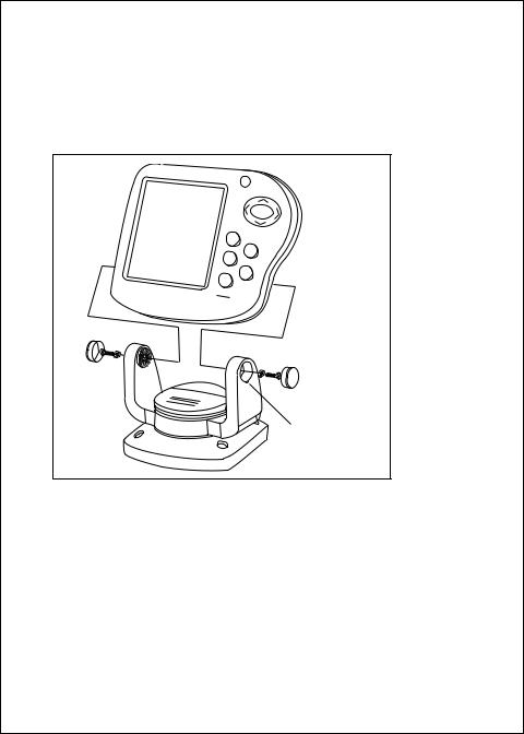
6.Separate the display unit from the mounting bracket. (See Fig. 2-13.) Press the large button in the center of the bracket to separate the bracket arms. The display unit is attached to the arms by two screws. Each screw is covered by a cap. Locate the small slot beside each cap and pry upward using a small screwdriver. Remove the caps, then the two screws and the two wave washers. Save these parts in case you ever want to use the mounting bracket.
Raymarine
PWR
SETUP
CLEAR
ZOOM
A-SCP
BOT
LOCK
FISHFINDER
L470
To pry up the cap, insert a small screwdriver here.
Fig. 2-13
Disassembling from Bracket
7.Screw the threaded studs into the holes on the rear of the display unit.
8.Set the display unit into place to be sure that it will fit correctly. Thread the wing-nuts onto the threaded studs to hold the display unit in place temporarily.
9.Once the DC wiring is complete, finish the installation. Hold the gasket in place around the opening. Fit the display into the cutout again. From the rear, screw the thumbscrews securely onto the threaded studs to hold the unit in place.
Installing the Transducer Cable
A 20 foot length of cable, with the connector attached, is supplied with the Downlooker transducer.
Installation |
19 |
Cable feed-thru cap
Cable clamp
1" (25 mm)
Hull projections
Fiberglass: 1/4" (6mm)
Aluminum: 1/2" (13 mm)
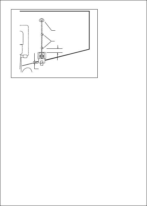
Fig. 2-14
Installing Cable on Transom
1.Route the cable up and over the top edge of the transom. See Fig. 2-14. Secure the cable using cable clamps. (These clamps are available from your local marine equipment supplier.)
If you do not want to expose the cable on the deck, you may drill a new hole (3/4" or 19 mm) through the transom for the cable. (Re- member–this hole must be large enough to accept the cable with the connector attached. Do not cut the cable!) To seal the opening, use a feed-thru cap where the cable passes through the transom.
2.Run the cable through the interior of the boat. If the transducer cable runs near another electrical wire, it may pick up electrical interference or “noise.” To reduce this, try to keep the transducer cable separated as far as possible from all other wires. This is especially important with wiring for the boat’s ignition, alternator, or tachometer. Also try to keep the transducer cable away from the antenna and power cables for VHF or FM radios. It is also helpful to keep the transducer cable away from the FishFinder power cable. If it is necessary to run the transducer cable across any wires, make the crossing at a right angle.
3.Be careful not to tear the cable jacket when passing it through bulkheads and other parts of your boat. Secure the cables in place using tywraps or lacing twine. Coil the extra cable and tie it out of the way.
4.If the 20 foot transducer cable is not long enough, a 15 foot extension cable (5M) is available from your Raymarine dealer (part no. M99-140).
20 |
Installation |
|
|
When you attach the extension cable, be sure that the connections are tight and watertight. Use Dow Corning DC-4 or an equivalent sealing compound to protect the connector assemblies.
5.At the rear of the display unit, plug in the transducer cable using the keyed connector.
Installing the Transducer Cable – Sidelooker Option
1.If the installation includes the optional Sidelooker transducer, there will be two transducer cables. See Fig. 2-15. The cable from the Sidelooker includes a “Y” connector, and is 12’ long (3.6 m).
2.Plug the cable from the depth transducer into the open end of the “Y” connector.
|
|
|
|
|
|
|
|
|
|
|
|
|
|
|
|
|
|
|
|
|
|
|
|
|
|
|
|
|
|
|
|
|
|
|
|
|
|
|
|
|
|
|
|
|
|
|
|
|
|
|
|
|
|
|
|
|
|
|
|
|
|
|
|
|
|
|
|
|
|
|
|
|
|
|
|
|
|
|
|
|
|
|
|
|
|
|
|
|
|
|
|
|
|
|
|
|
|
|
|
|
|
|
|
|
|
|
|
|
|
|
|
|
|
|
|
|
|
|
|
|
|
|
|
|
|
Sidelooker |
|
|
Fig. 2-15 |
||||||||||
|
|
|
|
|
|||||||||
transducer |
|
|
|||||||||||
|
|
|
|
|
|||||||||
Depth |
Cable for |
||||||||||||
transducer |
Sidelooker |
||||||||||||
Transducer |
|||||||||||||
|
|
|
|
|
|
|
|
|
|
|
|
||
Installing the Transducer Cable –
Installation with Separate Speed and Temperature Sensors
1.Optional depth-only and speedand temperature-only transducers are available for the FishFinder L470. In this optional configuration the separate transducers are connected via a “Y” type receptacle cable located on the optional speedand temperature-only transducer cable.
Installation |
21 |

2.Plug the cable from the depth-only transducer into the receptacle connector on the optional speedand temperature-only transducer. The speedand temperature-only transducer then connects at the transducer receptacle of the FishFinder L470. This is shown below in Fig. 2-16.
|
|
|
|
|
|
|
|
|
|
|
|
|
|
|
|
Fig. 2-16 |
|
|
|
|
|
|
|
|
|
|
|
|
|
|
|
|
|
|
|
|
|
|
|
|
|
|
|
|
|
|
|
|
|
|
|
|
|
|
|
|
|
|
|
|
|
|
|
|
|
|
|
|
|
|
|
|
|
|
|
|
|
|
|
|
|
|
|
|
|
|
|
|
|
|
|
|
|
|
|
|
|
|
|
|
|
|
|
|
|
|
|
|
|
|
|
|
|
|
|
|
|
|
|
|
|
|
|
|
|
|
|
|
|
|
|
|
|
|
|
|
|
|
|
|
|
|
|
|
|
|
|
|
|
|
|
|
|
|
|
|
|
|
|
|
|
|
|
|
|
|
|
|
|
|
|
Sensor for |
|
Sensor for |
||||||||||||
|
|
speed and |
|
depth only |
Cable for Speed |
|||||||||||
|
|
temperature |
|
|
|
|
|
|
|
|
|
|||||
|
|
|
|
|
|
|
|
|
|
|
and Temperature |
|||||
|
|
|
|
|
|
|
|
|
|
|
|
|
|
|
|
|
|
|
|
|
|
|
|
|
|
|
|
|
|
|
|
|
Sensor |
Making the DC Power Connections
1.The display unit is designed for use on boats with 12V DC power systems. (The unit can operate as long as the DC voltage is between 10.8 and 16V DC.) The display unit can be wired to a negativeground system, or both the negative and positive supply lines may be “floating” above ground. This unit is not intended for use on boats with positive ground.
2.The 6-foot power cable supplied with the display unit should reach the source of DC power. On a small boat, connect the power leads directly to the main battery isolation switch or breaker. On a larger boat, route the power leads to the DC power distribution panel.
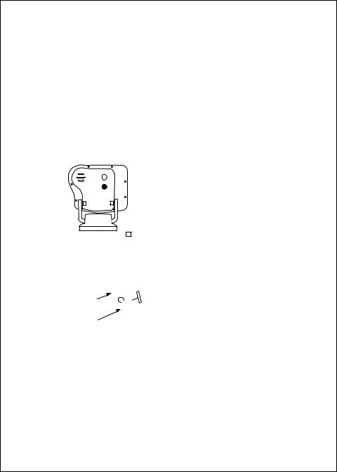
3.It is very important that you connect the power leads correctly. See Fig. 2-17. At the power source, connect the red wire to the positive
22 |
Installation |
|
|

RED
BLACK
DC 12V 
 RF ground
DC 12V connector to battery
T/D connector
to transducer
Fig. 2-17
DC Power
Connections
terminal (+), and the black wire to the negative terminal (-). The negative terminal may also be called “ground” or “earth.” (The display unit is internally protected if you accidentally reverse the polarity of the power wires.)
4.Attach the red or positive wire to a 5 amp circuit breaker. If the unit is connected directly to the boat’s battery, include a 2 amp in-line fuse. (In-line fuses are available at most marine supply stores.)
5.The power cable includes a smaller “shield” wire. Connect this to a good ground.
6.If you need to extend the power wiring by more than 10 feet, use a larger wire size. This will allow the wires to deliver the correct voltage in spite of the longer wire distance. For runs of 20 to 35 feet, use #14 AWG.
If you extend the power wiring, be sure all electrical connections are solid and durable. Soldering is the best way to make these connections. Insulate all connections using heat-shrink tubing or electrical tape. You may also use crimp connectors or a terminal strip, but be sure to use good-quality marine-grade parts.
7.At the rear of the display unit, plug in the power cable using the keyed connector.
Installation |
23 |

Note –
Press firmly when inserting the power cable and transducer cable to ensure a tight seal.
8.When you press the PWR button, the display unit should turn on. If the unit will not turn on and you suspect that you may have reversed the power connections, check the DC power lines all the way back to the battery. If the polarity is not correct, reconnect the leads properly and try again.
Calibrating the Sensors
The transducer most often used with this unit includes sensors for boat speed and water temperature. These sensors are normally very accurate, but you may want to calibrate them. The procedure appears on page 64. See the section on “System Setup Menu.”
The speed indication on your FishFinder is usually very accurate. However, there are some special cases where the speed reading may be high or low. This means that the speed of the water past the transducer may not be the same speed that your boat moves through the water. The hull of the boat may have a shape which channels water past the transducer at a speed which is faster or slower than normal.
1.To calibrate the speed sensor, set up a course between two known points. As markers you can use buoys, range markers, or landmarks. Measure the length of time the boat takes to cover a known distance.
2.You may also use locations indicated by a G.P.S. or Loran unit. (If you choose this method, remember that these devices measure “speed over ground” or “speed over the bottom.” Tides, currents, or winds can create a difference between the FishFinder’s “speed through water” measurement and the boat’s “speed over ground.” Before calibrating using a G.P.S. or Loran unit, wait for still water or slack tide conditions.
3.If the display unit is reading high or low, you can correct for this using the entry for “Speed Cal.” (To reach Speed Cal, go to the System Setup Menu. This is described in Section 4.) The entry for Speed Cal is a percentage. An entry of “100” equals 100%, meaning that there is no correction. If the display unit is producing a low reading, use a
24 |
Installation |
|
|
 Loading...