


Raynav 300 GPS
Plotter
Owner’s Handbook
Document Number: 81171_5
Date: September 2002
Prelim Pages |
iii |
Raynav 300 GPS Plotter Owner’s Handbook
SAFETY NOTICES
WARNING: NAVIGATION AID
This device is intended to be used as an aid to navigation. Its accuracy can be affected by many factors, including equipment failure or defects, environmental conditions and incorrect handling or use. It is the user’s responsibility to exercise common prudence and navigational judgement. This device should not be relied upon as a substitute for such prudence and judgement.
CAUTION:
Do not connect/disconnect the GPS Antenna from the display unit whilst power is applied. Such action could cause irreparable damage.
WAAS Satellite Differential GPS
WAAS provides differential augmentation to GPS. It was designed to enhance the basic GPS service to satisfy the aviation industry’s navigation requirement for instrument flight rule navigation and landing, IFR and approach landings. WAAS has been in near continuous broadcast since December 1999 and is also available for other GPS applications such as marine navigation, surveying, agriculture and automotive systems.
WAAS consists of a network of ground reference stations across the United States that monitor GPS satellite data. The master stations collect data from the reference stations and create a GPS correction message, taking into account selective availability (SA), GPS satellite orbit and clock drift, and signal delays caused by the atmosphere and ionosphere. The ‘corrected’ differential messages are then broadcast through two Geostationary Earth Orbit (GEO) satellites on the same frequency as the GPS signal. The Raymarine Raynav 300 and 301GPS receiver utilizes one of its 12 channels to ‘listen’ and decode the corrected WAAS messages. The result is a DGPS system that provides improved accuracy (<3 meters) in comparison with standard GPS (100 meters with SA, 15 m without SA) and land based DGPS (10 meters) systems.
The WAAS system is shown diagrammatically in Figure i.

iv |
Raynav 300 GPS Plotter |
|
Figure i: The WAAS System
Availability of the WAAS System in North America
The WAAS system is presently broadcasting and being tested for aviation use. It is expected to be certified by the FAA in 2002. During this testing and certification period, continuous service is expected; however, brief signal outages may occur as refinements and upgrades are made to the system. The status of WAAS and planned outages are available on-line at the following websites:
http://wwws.raytheontands.com/waas or http://www.raymarine.com
Your unit is shipped from the factory in normal GPS mode. For improved accuracy provided by the WAAS system, you need to enable the WAAS capability of your unit.
To enable WAAS:
1.Press the MENU key
2.Press GPS SETUP soft key
3.Press FIX MODE soft key to select SD mode.
Extended Offshore Coverage
Using two GEO satellites, WAAS provides augmented differential GPS coverage for most of North America. Since the WAAS differential messages are broadcast by GEO satellites, the WAAS signals cover a greater area both inland and offshore in comparison with land based DGPS systems. Coverage for North America is shown in Figure ii.

Prelim Pages |
|
|
|
|
|
|
|
|
|
|
|
|
|
|
v |
|
135˚E |
150˚E |
165˚E |
180˚ |
165˚W |
150˚W |
135˚W |
120˚W |
105˚W |
90˚W |
75˚W |
60˚W |
45˚W |
30˚W |
15˚W |
0˚ |
15˚E |
75˚N |
|
|
|
|
|
|
|
|
|
|
|
|
|
|
|
|
60˚N |
|
|
|
|
|
|
|
|
|
|
|
|
|
|
|
|
45˚N |
|
|
|
|
|
|
|
|
|
|
|
|
|
|
|
|
30˚N |
|
|
|
|
|
|
|
|
|
|
|
|
|
|
|
|
15˚N |
|
|
|
|
|
|
|
|
|
|
|
|
|
|
|
|
0˚ |
|
|
|
|
|
|
|
|
|
|
|
|
|
|
|
|
15˚S |
|
|
|
|
|
|
|
|
|
|
|
|
|
|
|
|
|
|
|
|
|
|
|
|
|
|
|
|
|
|
|
|
D4910-1 |
Figure ii: WAAS Coverage Map
Coverage Outside of North America
Europe and Asia are developing similar systems to WAAS called EGNOS and MSAS respectively. Combined with WAAS, these systems will provide global satellite based differential GPS augmentation into the future.
EGNOS is currently in the early testing and qualification phases and signal outages may occur at any time. The status of EGNOS and any planned outages are available on-line at Raymarine’s website: http://www.raymarine.com
Your unit is shipped from the factory in normal GPS mode. For improved accuracy provided by the EGNOS system, you need to enable the EGNOS capability of your unit.
To enable EGNOS:
1.Press the MENU key
2.Press GPS SETUP soft key
3.Press FIX MODE soft key to select SD mode.
Accuracy and Continuation of Broadcast Coverage
The navigational accuracy of equipment using these satellite broadcast SD signals during the testing and qualification phases is not guaranteed by Raymarine Limited or Raytheon Corporation, nor is the continuation of the broadcast SD signals the responsibility of Raymarine Limited or Raytheon Corporation.
vi |
Raynav 300 GPS Plotter |
Preface
This handbook covers the Raynav 300 GPS Plotter manufactured by Raymarine.
It contains important information on the installation and operation of your new equipment. In order to obtain the best results in operation and performance, please read this handbook thoroughly.
Raymarine’s Product Support representatives or your authorized dealer are available to answer any questions you may have.
Warranty
To register your Raynav 300 GPS Plotter ownership, please take a few minutes to fill out the warranty registration card found at the end of this handbook. It is important that you complete the owner information and return the card to the factory in order to receive full warranty benefits.
EMC Conformance
All Raymarine equipment and accessories are designed to the best industry standards for use in the leisure marine environment.
The design and manufacture of Raymarine equipment and accessories conform to the appropriate Electromagnetic Compatibility (EMC) standards, but correct installation is required to ensure that performance is not compromised.
Technical Accuracy
To the best of our knowledge, the information in this handbook was correct when it went to press. However, the Raymarine policy of continuous product improvement may change product specifications without notice.
Consequently, unavoidable differences may occur between the product and the handbook from time to time, for which Raymarine cannot accept liability.
Copyright © Raymarine Limited 2001
Raymarine® is a registered trademark of Raymarine Limited. SeaTalk® is a registered trademark of Raymarine Limited. SmartRoute™ is a trademark of Raymarine Limited.
C-MAP® and C-MAP NT® are registered trademarks of C-Map s.r.l.
Prelim Pages |
|
|
vii |
Contents - Raynav 300 Plotter |
|
||
|
SAFETY NOTICES......................................................................... |
iii |
|
|
WAAS Satellite Differential GPS ............................................. |
iii |
|
|
|
Availability of the WAAS System in North America ........... |
iv |
|
|
Extended Offshore Coverage ................................................ |
iv |
|
|
Coverage Outside of North America ...................................... |
v |
|
|
Accuracy and Continuation of Broadcast Coverage .............. |
v |
|
Preface ........................................................................................ |
vi |
|
|
|
Warranty ................................................................................ |
vi |
|
|
EMC Conformance ................................................................ |
vi |
|
|
Technical Accuracy ............................................................... |
vi |
Chapter 1: |
Overview .................................................................................. |
1-1 |
|
|
1.1 |
Introduction.............................................................................. |
1-1 |
|
|
How this Handbook is Organized ............................................ |
1-1 |
|
1.2 |
Features.................................................................................... |
1-2 |
|
|
General .................................................................................... |
1-2 |
|
|
Display .................................................................................... |
1-2 |
|
1.3 |
The Plotter Display .................................................................. |
1-3 |
|
|
Plotter Functions ..................................................................... |
1-3 |
|
1.4 |
Operating Controls................................................................... |
1-4 |
|
|
Trackpad and Cursor ............................................................... |
1-5 |
|
|
Dedicated Keys ....................................................................... |
1-6 |
|
|
Soft Keys ................................................................................. |
1-7 |
|
|
Pop-Up Menus ........................................................................ |
1-7 |
|
|
Database Lists ......................................................................... |
1-8 |
Chapter 2: |
Getting Started ....................................................................... |
2-1 |
|
|
2.1 |
Introduction.............................................................................. |
2-1 |
|
|
Conventions Used ................................................................... |
2-1 |
|
|
Simulator ................................................................................. |
2-1 |
|
2.2 |
Power On/Off........................................................................... |
2-1 |
|
|
Changing the Lighting and Contrast ........................................ |
2-3 |
|
2.3 |
Controlling the Display............................................................ |
2-4 |
|
|
Selecting the Display Mode .................................................... |
2-4 |
|
2.4 |
Plotter Display Control Functions............................................ |
2-6 |
|
|
Moving Around the Plotter Screen .......................................... |
2-6 |
|
|
Customizing the Display Options ........................................... |
2-8 |
|
|
Simulator Mode ....................................................................... |
2-9 |

viii
Chapter 3: |
Operation .................................................................................. |
3-1 |
|
3.1 Introduction.............................................................................. |
3-1 |
|
3.2 Changing the Display Mode.................................................... |
3-1 |
|
Data Display Pages .................................................................. |
3-2 |
|
GPS/Waypoint Data ................................................................ |
3-3 |
|
Boat/Environment Data ........................................................... |
3-6 |
|
CDI/BDI Data ......................................................................... |
3-9 |
|
Data Boxes ............................................................................ |
3-10 |
|
Data Log ................................................................................ |
3-11 |
|
3.3 Working with Waypoints........................................................ |
3-12 |
|
Introduction ........................................................................... |
3-12 |
|
Placing a Waypoint ............................................................... |
3-13 |
|
Selecting a Waypoint ............................................................. |
3-16 |
|
Waypoint Data Display .......................................................... |
3-17 |
|
Editing Waypoint Details ...................................................... |
3-17 |
|
Erasing a Waypoint ................................................................ |
3-19 |
|
Moving a Waypoint ............................................................... |
3-19 |
|
Using the ST60 or ST80 Navigator Keypad .......................... |
3-20 |
|
3.4 Working with Routes.............................................................. |
3-23 |
|
Creating a New Route ............................................................ |
3-24 |
|
Saving the Current Route ...................................................... |
3-27 |
|
Displaying Route Information ............................................... |
3-28 |
|
Clearing the Current Route from the Screen .......................... |
3-30 |
|
Retrieve a Route from the Database ...................................... |
3-32 |
|
Using the Route List to Erase or Name a Route ..................... |
3-32 |
|
Editing a Route ...................................................................... |
3-33 |
|
3.5 Following Routes and Going to Waypoints ........................... |
3-35 |
|
Going To an Individual Target Point ...................................... |
3-35 |
|
Follow a Route ....................................................................... |
3-36 |
|
Other Follow Route Options ................................................. |
3-37 |
|
Stop Follow or Stop Goto ...................................................... |
3-38 |
|
Target Point Arrival ............................................................... |
3-39 |
|
3.6 Transferring Waypoints and Routes....................................... |
3-40 |
|
Displayed SeaTalk Waypoints ............................................... |
3-40 |
|
Transferring Database Lists ................................................... |
3-40 |
|
3.7 Using Tracks .......................................................................... |
3-41 |
|
Setting Up a Track ................................................................. |
3-42 |
|
Clearing the Current Track .................................................... |
3-43 |
|
SmartRoute ............................................................................ |
3-44 |
|
Managing Tracks ................................................................... |
3-44 |
Prelim Pages |
|
|
ix |
|
3.8 |
Man Overboard (MOB) ........................................................ |
3-46 |
|
3.9 |
Alarms & Timers................................................................... |
3-47 |
|
3.10 Cursor Echo........................................................................... |
3-49 |
|
Chapter 4: |
Setting Up the GPS Plotter .................................................... |
4-1 |
|
|
4.1 |
Introduction.............................................................................. |
4-1 |
|
4.2 Changing the Set Up Parameters.............................................. |
4-2 |
|
|
4.3 System Set Up Parameters ....................................................... |
4-3 |
|
|
|
Bearing Mode .......................................................................... |
4-4 |
|
|
Cursor Reference ..................................................................... |
4-4 |
|
|
Cursor Readout ........................................................................ |
4-5 |
|
|
Day/Night ................................................................................ |
4-5 |
|
|
Help ......................................................................................... |
4-5 |
|
|
Soft Keys ................................................................................. |
4-5 |
|
|
Key Beep ................................................................................. |
4-5 |
|
|
MOB Data ............................................................................... |
4-5 |
|
|
Autopilot Pop Up ..................................................................... |
4-6 |
|
|
Menu Timeout Period .............................................................. |
4-6 |
|
|
Units ........................................................................................ |
4-6 |
|
|
Variation Source ...................................................................... |
4-6 |
|
|
NMEA OUT Set Up ................................................................ |
4-7 |
|
|
Cursor Echo ............................................................................. |
4-7 |
|
|
Date and Time Settings ............................................................ |
4-7 |
|
|
GPS Source ............................................................................. |
4-8 |
|
|
GPS SOG/COG Filter ............................................................. |
4-8 |
|
|
NMEA Input ............................................................................ |
4-8 |
|
|
Language ................................................................................. |
4-8 |
|
|
Simulator ................................................................................. |
4-8 |
|
4.4 Plotter Set Up Parameters ........................................................ |
4-9 |
|
|
|
Chart Orientation ..................................................................... |
4-9 |
|
|
Waypoint Symbols ................................................................ |
4-10 |
|
|
Waypoint Numbers ................................................................ |
4-10 |
|
|
Default Waypoint Symbol ..................................................... |
4-10 |
|
|
Vectors ................................................................................... |
4-10 |
|
|
Datum Selection .................................................................... |
4-11 |
|
|
Position Offset ....................................................................... |
4-11 |
|
4.5 GPS Set Up............................................................................. |
4-12 |
|
|
|
Fix Mode ............................................................................... |
4-12 |
|
|
D-GPS Set Up ........................................................................ |
4-13 |
|
|
Restart GPS ........................................................................... |
4-15 |
Chapter 5: |
Installation .............................................................................. |
5-1 |
|
|
5.1 |
Introduction.............................................................................. |
5-1 |
|
|
EMC Installation Guidelines ................................................... |
5-1 |

x
5.2 |
Unpacking and Inspecting the Components............................. |
5-3 |
|
Items Missing? ........................................................................ |
5-3 |
|
Registering this Product .......................................................... |
5-3 |
5.3 |
GPS Antenna Installation......................................................... |
5-4 |
|
Surface Mounting .................................................................... |
5-4 |
|
Pole Mounting ......................................................................... |
5-6 |
5.4 |
Plotter Installation .................................................................... |
5-7 |
|
Trunnion (yoke) Mounting ...................................................... |
5-8 |
|
Panel Mounting ....................................................................... |
5-9 |
5.5 |
Connecting to Other Equipment............................................. |
5-10 |
5.6 |
Cable Running........................................................................ |
5-11 |
|
Introduction ........................................................................... |
5-11 |
|
Connectors ............................................................................. |
5-11 |
5.7 |
System Check and Initial Switch On...................................... |
5-14 |
|
EMC Conformance ............................................................... |
5-14 |
|
System Check ........................................................................ |
5-14 |
|
Initial Switch On .................................................................... |
5-15 |
|
Checking the Plotter Operation ............................................. |
5-15 |
Chapter 6: Maintenance & Fault Finding ................................................. |
6-1 |
|
6.1 |
Maintenance............................................................................. |
6-1 |
|
Routine Checks ....................................................................... |
6-1 |
|
EMC Servicing and Safety Guidelines .................................... |
6-1 |
|
Disposal ................................................................................... |
6-2 |
6.2 |
Resetting the System................................................................ |
6-2 |
6.3 |
Problem Solving....................................................................... |
6-3 |
Appendix A: Technical Summary ............................................................ |
A-1 |
|
Appendix B: SeaTalk and NMEA Data..................................................... |
B-1 |
|
Appendix C: List of Abbreviations .......................................................... |
C-1 |
|
GPS Antenna Mounting Template ............................................................ |
T-1 |
|
Raynav 300 GPS Plotter Mounting Template ......................................... |
T-3 |
|
Index................................................................................................................ |
|
xi |
Chapter 1: Overview |
1-1 |
Chapter 1: Overview
1.1 Introduction
This handbook describes the Raynav 300 GPS Plotter.
Note: Many illustrations in this handbook show example screens. The screen you see on your display depends on your system configuration and set up options, so it may differ from the illustration.
How this Handbook is Organized
Chapter 1 - Overview (this chapter) provides an overview of the features and functions of the Raynav 300 GPS Plotter. You should read this chapter to familiarize yourself with the GPS Plotter.
Chapter 2 - Getting Started provides an overview of the controls. It also explains how to start using the GPS Plotter.
Chapters 3 - Operation provides detailed operating information for the main plotter functions - plotting waypoints and routes, following routes, using tracks, SmartRoute, Man Overboard and Data Log Mode.
Chapter 4 - Setting Up the GPS Plotter provides instructions for setting up your GPS Plotter system to suit your preferences. You should read this chapter to determine how to set up your system preferences.
Chapter 5 - Installation provides planning considerations and detailed instructions for installing the GPS Plotter.
Chapter 6 - Maintenance & Fault Finding provides information on user maintenance and what to do if you experience problems.
Appendix A lists the technical specifications for the GPS Plotter.
Appendix B defines the SeaTalk and NMEA data that is transferred on integrated systems.
Appendix C provides a list of abbreviations used in this handbook. An Index provides an easy lookup to specific keywords or topics. Installation Templates are included at the end of this handbook.
A summary of the GPS Plotter controls and functions are provided on the Quick Reference Card supplied with your system.
1-2 |
Raynav 300 GPS Plotter |
1.2Features
General
The Raynav 300 GPS Plotter has a built-in GPS that provides the following navigational signals:
•Satellite Differential GPS (eg, WAAS).
•Ground based Differential GPS, when used with an additional RTCM beacon receiver.
•Standard GPS.
These are listed in order of accuracy and their availability is dependent upon your location. The Raynav 300 GPS Plotter uses the best available signal to provide optimum accuracy.
The Raynav 300 GPS Plotter is waterproof to CFR46 and can be installed either above or below deck.
The unit comprises
•Low profile antenna
•4½ in. LCD display comprising:
•Eight dedicated (labelled) control keys
•Four soft keys with labels displayed on-screen
•Trackpad
The display and keys can be illuminated for night-time use.
Display
•Computes position information from SDGPS, DGPS or GPS
•Displays and transmits SeaTalk and NMEA data
•Cursor echo across SeaTalk
•Choice of orientation: Head Up, Course Up and North Up
Display Modes
The GPS Plotter can display data in the following modes, cycled through by means of the DISPLAY key:
•Default GPS/Waypoint display
•Boat Data (three pages) / Environment Data (two pages)
•Bearing & Distance Indicator (BDI) / Course Deviation Indicator (CDI)
•Data Boxes
•Data Log
•Plotter display
•Return to default GPS/Waypoint display
Chapter 1: Overview |
1-3 |
Those modes containing more than one page of data provide additional soft keys giving access to the sub-sets of data within each group, each cycled through with the associated soft key.
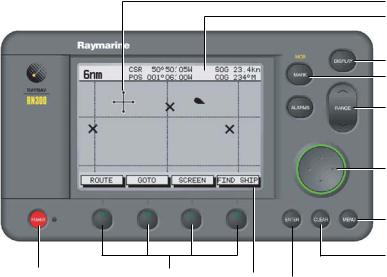
1.3 The Plotter Display
When a position fix has been established, your vessel’s position, if on screen, is shown as a boat shape, pointing in the direction of the current heading (or COG if heading data is not available). If no heading or COG data is available, the vessel is shown as a circle.
A status bar at the top of the screen displays the scale, with either cursor position, range and bearing or, when the cursor is homed (locked) to the vessel (by pressing FIND SHIP), vessel position, Speed Over Ground (SOG) and Course Over Ground (COG).
Note: When the cursor is homed, it is ‘locked’ to the vessel and moves with it. The screen is automatically panned to keep the vessel and cursor in such a position that they are 10% from the edge of the window with the heading vector (be it shown or not) passing through the center of the window.
The current route is shown and any waypoints you have placed are displayed (unless you set them to off in Set Up). Information can be viewed on-screen by positioning the cursor over a waypoint, current route or track.
Functions are available to control the display as follows:
•Zoom in/out
•Pan the Display
•Centre the Chart on the Vessel
Plotter Functions
Display Functions
The Raynav 300 GPS Plotter includes the following functions:
•Place, Move, Erase and Edit a Waypoint
•Goto Waypoint or Cursor
•Create, Save, Name, Edit and Follow a Route
•Review Route and Waypoint Lists
•Display vessel’s track; Save and Name the Track for re-call to screen
•Use SmartRoute to make the current track into a route
•Set Up Alarms and Timers
1-4 |
Raynav 300 GPS Plotter |
•Man OverBoard (MOB) to navigate back to a missing person or object
•Data Log display
For systems with an autopilot, when the status and locked heading information change, the new data can be displayed.
GPS Data Pages
Amongst a number of information pages, the GPS Data pages provide a series of four textual displays, selected by the associated soft key. These provide essential information associated with plotting a course for your vessel.
•Fix status
•Steering Indication
•Position Latitude/Longitude
•Waypoint Bearing and Range
•Course Over Ground (COG)
•Speed Over Ground (SOG)
•Current Time
•Sunrise and Sunset Times
•Twilight Times
The range of pages is detailed in Selecting the Display Mode on page 2-4. The complete range of pages is described fully in Data Display Pages on page 3-2.
1.4 Operating Controls
Operation utilizes a number of buttons and on-screen controls. These include:
•A trackpad providing up, down, left, right and diagonal control of an on-screen cursor.
•Eight dedicated (labelled) control keys.
•Four soft keys with labels displayed on screen.
•Pop-up menus, displayed on-screen, from which options are selected.
•Database lists, displayed on-screen, which enable editing of items.
Note: The cursor is the cross-hair symbol (+) visible on the display. The trackpad moves the cursor to select a position or item on the chart.
The controls are shown in Figure 1-1. They are back-lit for night-time use. When you use certain controls, a help message is displayed at the top of the screen (unless you switch help off as described in Chapter 4). The following paragraphs describe the controls and on-screen facilities.
Chapter 1: Overview |
1-5 |
Cursor
Status Bar
DISPLAY key
MARK key
RANGE key
 ALARMS key
Trackpad
MENU key
D4925_2
CLEAR key
POWER key |
Soft keys |
Soft key labels |
|
ENTER key |
|
Figure 1-1: Raynav 300 GPS Plotter Operating Controls
Trackpad and Cursor
The trackpad is used to:
•Move the cursor around the screen
•Select an item from a pop-up menu
•Adjust a variable soft key control The cursor is used to:
•Select a position on the screen.
•Select and, if valid, move an item, e.g. a waypoint, on the screen.
•Select an area of the screen to zoom into.
•Pan the display.
Moving the Cursor
Press the corresponding edge of the trackpad to move the cursor horizontally, vertically or diagonally; the longer you press, the faster the cursor moves. The current cursor position is shown in the Status Bar at the top of the display.
Note: When certain menus and soft keys are displayed, the cursor is not active. If you find that you cannot move the cursor, it may be because the unit is in one of these modes. Press CLEAR (repeatedly) until the default soft keys are displayed; the cursor should then respond.

1-6 |
Raynav 300 GPS Plotter |
Context-Sensitive Cursor Control
The cursor is context-sensitive. Some items on the screen have information associated with them. Whan you place the cursor over such objects, the information is displayed in a pop-up box. In addition, soft keys aredisplayed for certain items. For example, when you place the cursor over a waypoint, the waypoint data is displayed in a pop-up box and the waypoint soft keys are displayed.
Text Label |
Feature |
|
|
BOX |
Data box (any type) |
|
|
MOB |
Man Over Board marker |
|
|
WPT |
Chart Waypoint |
|
|
COG |
Course Over Ground vector |
|
|
HDG |
Heading vector |
|
|
POS |
Vessel’s position |
|
|
RTE |
Route leg |
|
|
TIDE |
Tide vector |
|
|
|
|
Dedicated Keys
The dedicated keys: DISPLAY, MARK, RANGE, ALARMS, ENTER, CLEAR, MENU and POWER have fixed functions.
Some keys can be used in two ways:
•Press: Press the key momentarily and then release it. This method is used for most key operations.
•Press and hold: Press the key and hold it down for the length of time stated (for example, 3 seconds), then release it.
When you press a dedicated key, one of the following happens:
1.The associated operation is actioned, eg. change chart scale (RANGE).
2.A pop-up menu is displayed, providing further options.
3.A set of soft keys is displayed, providing further functions.
As you press a key, a single audio beep confirms the key action. If the key-press is invalid for the current screen or mode, three rapid beeps sound. If required, you can turn these sounds off as part of your set up procedure (see System Set Up Parameters on page 4-3).

Chapter 1: Overview |
1-7 |
Soft Keys
The four keys below the screen are called soft keys because their functions change according to the operation. The soft keys are grouped into related sets and subsets providing access to the various functions. The soft key labels are displayed on the screen just above the keys. The default soft keys are displayed until you press a key, or select an item on the screen; the soft keys associated with the action are then displayed as shown in Figure 1-2.
ROUTE GOTO SCREEN FIND SHIP
D4897-1
Figure 1-2: Default Soft Keys
Note: If the key text is greyed out, it is not currently available.
When you press a soft key, one of the following happens:
1.The associated operation is actioned.
2.A sub-set of soft keys is displayed, providing further functions.
3.A pop-up menu is displayed, providing further options.
As with dedicated keys, soft key operations are confirmed (or denied) by key beeps, see Dedicated Keys above.
Pop-Up Menus
Pop-up menus usually provide set up options. When a pop-up menu is on-screen, a set of associated soft keys is also displayed as shown in
Figure 1-3.
ALARMS SET UP
ARRIVAL ALARM |
0.01nm |
|
OFF TRACK |
ALARM |
ON |
|
|
|
ANCHOR ALARM |
OFF |
|
COUNTDOWN |
TIMER |
00:10:00 |
ALARM CLOCK |
OFF |
|
|
ALARM |
|
|
SELECT DISTANCE |
|
|
|
|
|
||
|
OFF ON |
|
|
|
|
|
|
|
|
|
|
D4898_2
Figure 1-3: Typical Pop-up Menu
Use the trackpad to select an option from the menu, then use the appropriate soft key to set the option. For example, you can toggle the ANCHOR ALARM on/off using the soft keys.

1-8 |
Raynav 300 GPS Plotter |
Database Lists
The waypoints, routes and tracks created on the display unit are stored in database lists. You can view these lists and select items for editing as shown in Figure 1-4.
WAYPOINT LIST
|
|
|
SYMBOL |
|
|
|
NAME |
|
|
||||
|
|
|
|
|
|
|
|
|
|
|
|
||
|
|
|
|
|
|
|
|
|
WPT 001 |
|
|
||
|
|
|
|
|
|
|
|
|
WPT 002 |
|
|
||
|
|
|
|
|
|
|
|
|
WPT 003 |
|
|
||
|
|
|
|
|
|
|
|
|
WPT 004 |
|
|
||
|
|
|
|
|
|
|
|
|
|
||||
|
|
POSITION |
|
|
N |
50°50^000 |
|
||||||
|
|
|
|
|
|
|
|
|
W 001°06^000 |
|
|||
|
|
BRG |
|
348°m |
RNG |
1.00nm |
|||||||
|
|
TEMP |
|
|
20°C |
DEPTH 12.3m |
|
|
|||||
|
|
DATE |
23/11/01 |
TIME |
08:45:12 |
|
|||||||
|
|
|
|
|
|
|
|
|
|
|
|
|
|
|
|
|
|
|
|
|
|
|
|
|
|
|
|
|
GOTO |
|
|
EDIT |
|
|
MAKE NEW |
|
WAYPOINT |
||||
|
WAYPOINT |
|
|
WAYPOINT |
|
|
WAYPOINT |
|
TRANSFER |
||||
D4906-2
Figure 1-4: Typical Waypoint List
As with pop-up menus, when a database list is on-screen, a set of associated soft keys is also displayed. Use the trackpad to select an item from the list, then use the appropriate soft key to select the function.
Chapter 2: Getting Started |
2-1 |
Chapter 2: Getting Started
2.1 Introduction
This chapter provides information, instructions and a simple familiarization exercise in using the display. Operating information is detailed in Chapter 3.
Conventions Used
Throughout this handbook, the dedicated (labelled) keys are shown in bold capitals; for example, ENTER. The soft key functions, menu names and options are shown in normal capitals; for example, SCREEN.
Operating procedures, which may consist of a single key-press or a sequence of numbered steps, are indicated by a symbol in the margin.
Simulator
The plotter display unit includes a Simulator mode, which allows you to practice operating your plotter without data from a GPS antenna. You will need to use the set up options to switch the display unit to Simulator mode, see Section 2.2, Power On/Off. You can use it in either of two ways:
•Before the plotter has been installed on your vessel. In this case, you only need to connect the plotter display unit to a 12V DC power supply, fused at 1A, connecting the red core from the power lead to positive (+) and the black core to negative (-); see Cable Running on page 5-11 for full details.
•After the plotter has been installed on your vessel, but while in the marina or at anchor.
2.2Power On/Off
To turn the display unit on, press the POWER key.
The keys light up and the introductory logo is displayed.
The GPS Status screen is displayed as shown in Figure 2-1.

2-2 Raynav 300 GPS Plotter
GPS STATUS
SAT SIGNAL STATUS SAT SIGNAL STATUS
15  LOCKED 23
  LOCKED
09  IN USE 18
  IN USE
08  IN USE 26
  IN USE
10  LOCKED 12
  LOCKED
20  LOCKED 14
  LOCKED
17  LOCKED 03
  LOCKED
HDOP |
|
FIX STATUS |
|
|
|
1.0D-FIX
|
FIX |
MODE |
|
D-GPS |
|
|
RESTART |
||
|
GPS |
D |
SD |
|
|
SET UP |
|
|
GPS |
|
|
|
|
|
|
|
|
|
|
D5551_1
Figure 2-1: GPS Status Screen
The GPS Status screen is displayed until a satellite fix has been acquired. When satellite acquisition is complete, the READY FOR NAVIGATION pop-up box displays for two seconds.
To proceed whilst satellite acquisition continues, press the CLEAR key; the GPS Data Screen is displayed.
SD-FIX |
WPT BRG |
|
320°M
50°50^000N WPT RNG
001°06^000W 0.55nm
COG
|
|
|
|
|
|
|
|
|
050°M |
|
|
|
|
|
|
|
|
|
|
|
|
|
|
|
|
|
|
|
|
|
|
SOG |
|
STEER STARBOARD |
|
12.0kts |
|||||||
|
|
|
|
WPT 004 |
|
|
|
|||
|
|
|
|
|
|
|
|
|
|
|
|
|
|
|
|
|
|
|
|
||
|
ROUTE |
|
|
GOTO |
|
GPS DATA |
|
WPT DATA |
||
|
|
|
|
|
|
|
|
|
|
|
D4936-1
Figure 2-2: GPS Data Screen
To switch the display unit off, press and hold the POWER key for at least three seconds. A 3-second countdown timer is displayed; when it reaches
Chapter 2: Getting Started |
2-3 |
zero the display and key backlights extinguish. If the POWER key is released within this period, power-down is cancelled.
Changing the Lighting and Contrast
You can change the level of backlighting and contrast for the screen and keys. The key backlighting always retains a minimal level to enable the keys to be seen at night.
To change the lighting and contrast:
1. Press the POWER key to display the lighting controls (Figure 2-3).
ON
42% 60%
LIGHT CONTRAST
D4927_1
Figure 2-3: Lighting Controls
2.Use the LIGHT soft key or trackpad left/right to select LIGHT control.
•Use the LIGHT soft key to toggle lighting ON/OFF.
•Use trackpad up/down to select lighting level (eight levels).
3.Press the CONTRAST soft key, or trackpad left/right, to select the CONTRAST control. Adjust the contrast setting in the same way as for the lighting (100 contrast levels).
4.Press ENTER to remove the soft key sliders and return to the default screen, with the new lighting and contrast levels retained.
When the display unit is switched on, screen lighting is restored to ON if it was ON previously. Whilst the unit is switched on, the chosen lighting level is retained until it is reset. The new contrast level is retained until it is reset, even after power-off, unless it has been set either very low or very high; in this case, the contrast will be restored on power-up as follows:
•Contrast set <30% restored to 30%
•Contrast set >70% restored to 70%
Note: Factory default settings are LIGHT OFF and CONTRAST 50%.

2-4 |
Raynav 300 GPS Plotter |
2.3 Controlling the Display
The display is controlled by means of the cursor and control keys. Most plotter operations are started from the default soft keys displayed in the plotter screen (Figure 2-4).
ROUTE GOTO SCREEN FIND SHIP
D4897-1
Figure 2-4: Default Soft Keys
On completion of an action using the soft keys, press CLEAR to return to the default screen; you may need to press CLEAR several times to back-track through the soft key hierarchy.
Note: If you have set up your system so that the default soft keys are not permanently displayed, press any soft key to display the labels.
Selecting the Display Mode
The DISPLAY key is used to select the desired display mode. The following modes can be selected.
Select the following modes by repeat presses of the DISPLAY key (Figure 2-5):
•GPS/Waypoint display
•Boat Data (three pages)-Environment Data (two pages)
•Course Deviation Indicator (CDI)-Bearing/Distance Indicator (BDI)
•Data Boxes
•Data Log
•Plotter display
•Return to GPS/Waypoint display
The complete ranges of pages available in Boat and Environment Data modes are described in Chapter 3.

Chapter 2: Getting Started |
2-5 |
Press
POWER
... after preliminary displays, the default display is shown
|
|
SD-FIX |
|
|
|
|
OWN POS |
|
|
|
|
|
|
|
XTE |
|
|
Waypoint data |
SD-FIX |
|
|
|
|
|
||
|
|
|
|
XTE |
|
|||
|
|
SD-FIX |
|
|
|
|
|
|
|
SD-FIX |
|
|
|
XTE |
|
||
|
|
|
|
320°M |
|
|||
|
SD-FIX |
|
WPT BRG |
|
||||
|
|
|
|
WPT RNG |
|
|||
GPS data |
SD-FIX |
|
WPT BRG |
|
|
|||
|
WPT BRG |
|
|
|
||||
|
SD-FIX |
|
|
0.55nm |
|
|||
Press |
50°50^000W |
352°M |
COG |
Press |
||||
WPT RNG |
|
SOG |
||||||
|
|
|
050°M |
|
||||
|
0.55nm |
SOG |
|
|||||
DISPLAY |
|
|
|
SOG |
DISPLAY |
|||
|
|
STEER STARBOARD |
|
|
|
|
||
|
|
WPT 04 |
COG |
|
SOG WPT DATA |
|
||
|
|
|
|
|
||||
to return to |
001°06^000W |
|
SOG |
WPT DATA |
to show |
|||
|
050°M |
|
|
|||||
GPS/Waypoint |
|
|
|
GPS DATASOG |
WPT DATA |
Boat/Environment |
||
STEER STARBOARD |
SOG WPT DATA |
|||||||
Data |
|
WPT 004 |
|
WPT DATA |
Data |
|||
|
|
|
12.0kts |
|
|
|||
|
|
|
|
WPT DATA |
|
|||
|
ROUTE |
GOTO |
GPS DATA WPT DATA |
|
|
|||
6nm |
CSR |
50°50^05W |
SOG |
23.4kn |
POS |
001°06^00W |
COG |
234°M |
ROUTE |
GOTO |
SCREEN |
FIND SHIP |
|
|
|
|
Environment data |
|
APPARENT WIND |
|
|
|
|
WIND |
|||||
|
|
|
|
|
WIND |
|
||||||
|
TRUE WIND |
|
|
|
|
|
|
|
|
|
|
|
|
|
|
|
|
|
|
|
|
|
|
||
SD-FIX |
|
|
|
WPT BRG |
|
|
||||||
|
|
|
|
|
|
|
|
|
|
|||
|
|
|
|
|
|
|
|
|
|
|||
Boat data |
DEPTH 12. |
5MWPT |
|
BRG |
|
|
|
|
||||
SD-FIX |
|
|
WPT |
BRG |
|
|
|
|
||||
|
|
|
|
WPT |
RNG |
|
|
|
||||
SD-FIX |
|
|
320° |
|
|
|
|
|
|
|||
|
|
|
|
|
M |
|
|
|
|
|||
|
|
|
|
|
|
|
|
|
|
|||
|
SPEED 11k |
|
tsWPT |
RNG COG |
|
|
|
|||||
|
|
|||||||||||
DEPTH 12.5m |
|
|
|
|
050°M |
|
|
|||||
|
|
|
0.55nm SOG |
|||||||||
|
STEER STARBOARD |
COG |
SOG |
||
|
|
||||
|
WPT 004 |
|
|
SOG |
|
|
|
050°M |
|||
SPEED 11kts |
|
||||
|
|
|
|
SOG WPT DATA |
|
STEER STARBOARD |
GPS DATASOG |
WPT DATA |
|||
|
WPT 004 |
|
|
WPT DATA |
|
|
|
12.0kts |
|||
|
|
|
|
WPT DATA |
|
ROUTE |
GOTO |
BOAT DATA ENVIROMNT |
|||
Press DISPLAY to show
Plotter Display
TIME POSITION CMG DMG
09:00 |
50°50^000N |
239°m |
4.8nm |
20/12 |
001°06^000W |
|
|
09:30 |
50°51^000N |
241°m |
5.2nm |
20/12 |
001°07^000W |
|
|
10:00 |
50°52^000N |
240°m |
4.5nm |
20/12 |
001°08^000W |
|
|
ROUTE |
GOTO |
STOP LOG |
CLEAR LOG |
Note: In any display mode press DISPLAY key for 2 seconds to return to default display.
|
|
|
|
|
Press |
DISPLAY |
to show |
|
|
|
||||||
|
|
|
|
|
|
|
|
CDI or BDI |
|
|
|
|||||
|
|
|
|
|
|
|
|
|
|
|
|
|
|
|
|
|
|
|
|
|
|
|
225°T |
|
|
|
|
|
|
|
XTE |
|
|
|
|
|
|
|
355°T |
|
|
|
XTE |
|
|
0.05nm |
||||
|
|
|
40 |
|
|
|
|
40 |
|
|
|
WPT BRG |
||||
|
|
|
|
|
|
|
|
|
|
0.05nm |
|
|
||||
|
|
|
30 |
|
|
|
|
30 |
|
|
|
|
300°T |
|||
|
|
|
20 |
|
|
20 |
WPT BRGWPT RNG |
|||||||||
|
|
|
|
|
300°T |
|
|
|||||||||
|
|
|
nm |
|
|
|
nm |
23.2nm |
||||||||
|
|
|
10 |
|
10 |
|
|
WPT RNG |
TTG |
|||||||
|
|
|
|
|
|
|
|
|
|
|||||||
|
|
|
|
|
STEER STARBOARD |
23.2 |
|
|
|
|
||||||
|
|
|
|
|
nm04h 12m |
|||||||||||
|
|
|
|
|
WPT 004 |
|
|
TTG |
|
|
|
|
|
|
||
|
|
|
|
|
|
|
|
|
|
|
|
|
|
|
||
|
|
|
|
|
|
|
|
|
|
|
|
|
|
|
||
|
STEER STARBOARD |
|
|
BDI |
|
|
|
|
BDI |
|
||||||
|
|
|
|
|
WPT 004 |
|
|
|
04h:12 |
|
m |
|
||||
|
|
|
|
|
|
|
|
|
|
|
|
|
|
|
||
|
|
|
|
|
|
|
|
|
|
|
|
|
||||
|
ROUTE |
|
|
GOTO |
|
CDI |
|
|
BDI |
|
|
|
||||
|
WPT RNG |
WPT BRG |
PILOT |
|
|
|
Press |
28.7nm |
124°T |
|
MANUAL |
|
Press |
|
|
|
|
|
||
|
TIME |
SPEED |
|
|
|
|
DISPLAY |
COG |
DISPLAY |
||||
10:40:18 |
17kts |
|
124°T |
|
||
|
|
|
|
|||
to show |
|
|
|
|
|
to show |
DEPTH |
POSITION |
|
|
|||
SOG |
||||||
Data Log |
36.5ft |
50°50^000N |
|
15.1kts |
|
Data Boxes |
|
001°06^000W |
|
|
|
||
|
|
|
|
|
|
|
|
ROUTE |
GOTO |
|
|
|
|
D4964-2
Figure 2-5: Display Modes
2-6 |
Raynav 300 GPS Plotter |
2.4 Plotter Display Control Functions
You will normally operate the GPS Plotter with the display showing one of the Navigation Data pages.
The range of pages is listed in Selecting the Display Mode on page 2-4 and illustrated in Figure 2-5. The complete range of pages is described fully in Data Display Pages on page 3-2.
Moving Around the Plotter Screen
When using the plotter screen, the default orientation is North-Up, where the vessel moves across the screen. You will need to pan the display if your vessel moves out of the current area, or if you wish to examine or place waypoints in another area. Alternatively, you can home the cursor onto the vessel using FIND SHIP.
There are four ways in which you can move around the display:
•Use the trackpad to pan the display.
•Automatically home (re-center) the vessel using the FIND SHIP soft key.
•Use the context-sensitive cursor to change the display center.
•Change the display scale to zoom out and in to a new area centered on the cursor position. This method is useful if the area you wish to see is a long distance away.
Panning the Display
Panning the display is useful if the area you wish to see is only just off the screen.
Use the trackpad to move the cursor to the edge of the display; the display will pan across.
Using FIND SHIP
FIND SHIP is used to center the vessel on the screen, even if it is currently off screen:
Press the FIND SHIP soft key; the following actions occur:
•The display is re-drawn with the vessel’s position in the center.
•The cursor is homed (locked) to the vessel’s position and moves with it.
•When the vessel moves near the edge of the screen, the display is redrawn to place the vessel and cursor at the center.
•Whilst homed, the status bar indicates vessel position, speed and course over ground.
Chapter 2: Getting Started |
2-7 |
To release the cursor from homed mode, use the trackpad to move the cursor away from the vessel’s current position. The status bar shows the current cursor position, bearing and range. The cursor no longer moves with the vessel and no redraw occurs if the vessel moves off screen.
Changing the Display Center
You can move the area of the display center using the context-sensitive cursor. This allows you to center your vessel in the center of the screen, or to move the display so that your vessel is displayed off-center anywhere on the screen.
To move your vessel’s position off-center:
1.Move the cursor over your vessel’s position until the letters POS are displayed.
2.Press ENTER to take control of the vessel’s position. The letters POS are now in inverse video and the cursor symbol has changed to a four-way arrow. This indicates that the cursor can be used to move the display in any direction.
3.Use the trackpad to move the cursor to the required position.
4.Press ENTER to select the position and return to normal cursor control. The display is redrawn with the vessel’s position at the cursor. Alternatively, you can press CLEAR to abandon the move and leave the display (and vessel) in its former position.
To center the display:
1.Use the trackpad to move the cursor to the vessel’s position. The cursor text POS is displayed.
2.Press CLEAR. The display pans to show your vessel’s position is in the center of the screen.
Changing the Display Scale
The RANGE key allows you to change the display scale so that you can see a smaller or larger area on the screen.
You can change the display scale:
•To see either a larger scale (of a smaller area) or a larger area (at a smaller scale) on the screen.
•To move the display to another area, by zooming out to a smaller scale, then zooming in on another position centered on the cursor.
Each time you press the RANGE key, the display scale changes to the next available setting. The status bar, shown in Figure 2-6, indicates the distance from top to bottom of the screen, in nautical miles.

2-8 |
|
|
Raynav 300 GPS Plotter |
|
|
6nm |
VES 43°27^05N |
SOG 23.4kts |
|
|
POS 001°02^83W |
COG 234°M |
|
|
|
|
|
D4902-1 |
|
|
|
Figure 2-6: Status Bar |
|
|
To change the scale rapidly, press and hold top or bottom of the RANGE key.
The distance indicator at the left-hand side of the status bar is updated whenever you change the display scale.
To zoom in to a larger-scale (more detailed) display:
1.Use the trackpad to position the cursor in the area you wish to see in larger scale.
2.Press the bottom of the RANGE key to zoom into the area.
The display, centered on the cursor, is enlarged to show a larger scale and the distance indicated in the status bar is updated.
To zoom out to a smaller-scale (less detailed) display, press the top of the RANGE key as many times as required, up to the maximum scale of 1200nm.
Customizing the Display Options
The SCREEN soft key enables the following screen display options to be set on or off:
•Cursor Box (CRSR BOX)
•Grid (GRID)
•Personalized (CUSTOM)
The factory default for these options is ON.
Switching the Cursor Data Box On/off
The cursor data box provides the cursor’s position in latitude/longitude and/or bearing/range.To see a full image, switch the data box off.
To control the cursor data box:
1.Press the SCREEN soft key.
2.Press the CRSR BOX soft key to toggle the setting between ON and OFF.
To return to the default soft key display, press CLEAR.
To move the cursor box:
1.Use the trackpad to position the cursor over the box until the letters BOX are displayed.
2.Press ENTER to take control of the box, use the trackpad to move it to the required position and press ENTER again.
Chapter 2: Getting Started |
2-9 |
Switching Grid On/off
The Plotter display can be set to show grid lines of latitude and longitude which can help determine position.
To turn the grid on or off:
1.Press the SCREEN default soft key.
2.Press the CHRT GRID soft key to toggle the setting ON and OFF.
3.To return to the default soft key display, press CLEAR.
Simulator Mode
When simulator mode is started, your initial simulated position is wherever the cursor was last positioned. To practice using the Plotter in a particular area, use the trackpad to pan to that area, then switch simulator
ON.
A data box indicating SIMULATOR ON is displayed in the center of the screen (this may obscure the cursor; if necessary use the trackpad to move the cursor into view). You can use the context-sensitive cursor to move this box
Note: If you use FIND SHIP when in Simulator mode, the Status Bar at the top of the screen shows SIM FIX. If real position data is available (via GPS) and the simulator is active, simulated data takes precedence.
On power-up the simulator defaults to its previous setting at last pow- er-down. Care should be taken to determine desired mode on power-up.
Simulated data should never be used for navigational purposes.
Any waypoints placed on the plotter in simulator mode are retained in the Waypoint List and are available for use in routes.
To view a simulated display:
1.Press MENU followed by the SYSTEM SET UP soft key. The System Set Up menu pop-up is displayed.
2.Use the trackpad up/down to move the selection bar over the option SIMULATOR. The simulator soft keys are displayed.
3.Press the ON soft key to start simulation.
4.Press ENTER twice to return to the default display.
2-10 |
Raynav 300 GPS Plotter |
Chapter 3: Operation |
3-1 |
Chapter 3: Operation
3.1 Introduction
This chapter explains how to navigate with the Raynav 300 GPS Plotter. It covers the following topics:
•Controlling waypoints, including placing, moving, editing and deleting waypoints.
•Changing the display mode.
•Using a range of data pages to display navigation data.
•Maintaining a Data Log of Time, Position, Course Made Good (CMG) and Distance Made Good (DMG).
•Working with waypoints and routes, including creating a new route, managing routes using the Route List and editing routes.
•Following routes and going to waypoints.
•Transferring waypoints and routes
•Using tracks, including showing tracks, track set up, saving tracks and converting a track to a route (SmartRoute).
•Using the Man Overboard (MOB) feature.
•Setting up Alarms and Timers.
•Cursor echo from other equipment.
CAUTION:
The GPS Plotter makes it easy to place a waypoint and travel towards it. However, you should always check first that the route is safe. When using the GPS Plotter in combination with a SeaTalk autopilot, the autopilot will prompt for confirmation before it steers the vessel towards the waypoint.
3.2 Changing the Display Mode
The DISPLAY key is used to select the desired screen mode. The following modes can be selected:
•Default GPS/Waypoint display
•Boat Data (three pages) / Environment Data (two pages)
•Course Deviation Indicator (CDI)/Bearing & Distance Indicator (BDI)
•Data Boxes
•Data Log
•Plotter display
•Return to default GPS/Waypoint display
3-2 |
Raynav 300 GPS Plotter |
The modes that contain more than one page of data provide additional soft keys which cycle through the pages. The highlighted soft key indicates the screen mode currently displayed.
Note: Press the DISPLAY key for at least two seconds in any display mode to return to the GPS/Waypoint display.
Data Display Pages
In all graphical display pages, the steering instruction is STEER STARBOARD if the XTE is 0.01nm or more to port, STEER PORT if the XTE is 0.01nm or more to starboard or ON COURSE if XTE is less than 0.01 on either side.
If no Goto or follow is in progress, the steering instruction is NOT FOLLOWING and no steering arrows are shown.
The arrows either side of the steering instruction and pointing towards it are dependent on the XTE. The first arrow is shown when the difference reaches 0.01nm and the second at 0.05nm.
Textual data provides Position, SOG, COG, Bearing and Range to waypoint, Time and Date, Time To Go (TTG), Steering Indicator, Sunrise, Sunset, Fix Status and XTE. Any unavailable data is replaced by dashes, one per character. When there is no GPS fix but there is a value for the last fix, this is shown instead.
The waypoint name is shown unless there is no target, in which case NOT FOLLOWING is shown. If Goto cursor is in progress, GOTO CURSOR is shown.
The FIX status indicates D-FIX for a differential fix, SD-FIX for a satellite differential fix, FIX for a GPS or other Fix, or NO FIX where a fix has not been acquired. If the simulator is ON, the word SIMULATOR appears after the fix status.
BRG, RNG and XTE data relate to the target waypoint.
Time refers to local time zone which is set in the System Set Up menu, see
Chapter 4.
The Time To Go (TTG) and Estimated Time of Arrival (ETA) data relate to the target waypoint (not the whole route) and are based on the Speed Over Ground (SOG) towards the target. If the Velocity Made Good (VMG) is negative, or data is not available, these fields are replaced by dashes, one per character.
Sunrise and Sunset times are for today and at the vessel’s position.
 Loading...