


Ray230
Ray230e
Modular VHF Radio
O w n e r ' s H a n d b o o k
RAY230 & RAY230E
Modular
VHF Radio
Owner’s
Handbook
Document number: R49006_2
Date: December 2001

iii
Purpose
This handbook contains very important information on the installation, operation, and maintenance of your RAY230 US version or RAY230E European version VHF radio. To get the best results in operation and performance, please take the time to read this handbook thoroughly.
RAY230 US Version
Raymarine radios comply with the Federal Communications Commission (FCC) and Industry Canada requirements that regulate marine VHF radio usage for the US and Canada, respectively.
Marine VHF radio users in the US must comply with all applicable FCC rules and regulations, some of which are described here and in Section 5. This information was current at the time this handbook was printed. Up- to-date information, including licensing requirements, can be obtained on the FCC website at:
www.fcc.gov/wtb/marine
Official FCC forms can be obtained on the FCC website at:
www.fcc.gov/formpage.html
FCC NOTICE
This device complies with Parts 15 and 80 of the FCC Rules. Operation is subject to the conditions that this device does not cause harmful interference. Changes or modifications to this equipment not expressly approved in writing by Raymarine, Incorporated could violate compliance with FCC rules and void the operator’s authority to operate the equipment.
Station License
An FCC Ship Radio Station License and Call Sign are not required for most recreational vessels travelling in US waters. Examples of radio equipment that do not require a license include: marine VHF radios, any type of Emergency Position Indicating Radio Beacon (EPIRB), any type of radar, GPS or LORAN receivers, depth finders, CB radio, or amateur radio (an amateur license is required). However, you must obtain a license if: (1) you are required by law or treaty to carry a radio on your vessel; (2) your vessel travels to foreign ports; (3) you use marine radio equipment on board your vessel other than the devices listed above. Ships that use MF/HF single side-band radio, satellite communications, or telegraphy must be licensed by the FCC. If necessary, you can obtain a Station License by filing FCC Form 605, which is available from the FCC website listed above.

iv
Operator License
An Operator License is not required to operate a VHF Marine Radio within US territorial waters. However, a license is required to operate the radio if you dock in a foreign port (including Canada and Mexico) or leave a foreign port to dock in a U.S. port. You can request a Restricted Radiotelephone Operator Permit from the FCC by filing Form 753.
Maritime Mobile Service Identity (MMSI)
A nine-digit Maritime Mobile Service Identity (MMSI) number is required to operate the DSC equipment in this radio. You can request an MMSI number from the FCC when you apply for a Station License. If your vessel does not require a license, you may obtain an MMSI by contacting either BoatUS (www.boatus.com) or MariTEL (www.maritelusa.com).
Once obtained, you can program the MMSI number into your RAY230 using the Menu Operation described in this handbook.
INDUSTRY CANADA
You do not need a license to operate this radio within sovereign waters of Canada or the US. You will need a license to operate this radio outside of Canada or the US. To obtain Industry Canada licensing information, contact the nearest field or regional office, or write:
Industry Canada
Radio Regulatory Branch Attention: DOSP
300 Slater Street
Ottawa, Ontario
Canada, KIA OC8
The following information about the radio is required to complete the license application:
Industry Canada Certification Number |
4069823227AD |
FCC Type Number |
PJ5RAY230 |
FCC Type Accepted |
Parts 15 and 80 |
Output Power |
1 watt (low) & 25 watts (high) |
Modulation |
16FE (FM) |
Frequency Range |
156.025-157.425 |

v
RAY230E European Version
The RAY230E is a VHF radiotelephone that includes equipment for Class “D” Digital Selective Calling. It is intended for general communication within the Maritime Mobile Service worldwide and is for use on nonSOLAS vessels.
License
Regulations in some areas require that you obtain an operator license before operating VHF radio equipment. It is your responsibility to determine whether a license is required in your area before operating this equipment.
Maritime Mobile Service Identity (MMSI)
An MMSI number is required to operate the Digital Selective Calling (DSC) equipment in this radio. In some areas, a radio operator license is required before an MMSI number will be issued. You can request an MMSI number from the same agency that issues radio operator licenses in your area. You can then program the MMSI number into your RAY230E using the Menu Operation described in this handbook. If regulations in your area do not permit you to program the MMSI number yourself, your Raymarine dealer can program the number for you.
Automatic Transmission Identification System (ATIS)
Your RAY230E can activate the ATIS feature, if needed. You can request an ATIS number from the same agency that issues radio operator licenses in your area. You can then program the ATIS number into your RAY230E using the Menu Operation described in this handbook. If regulations in your area do not permit you to program the ATIS number yourself, you can have your dealer program the number for you. You must only enable this feature when operating the radio in the inland waterways of European countries that require automatic identification transmission.
SAFETY NOTICE
This device is only an aid to navigation. Its performance can affected by many factors including equipment failure or defects, environmental conditions, and improper handling or use. It is the user's responsibility to exercise common prudence and navigational judgement, and this device should not be relied upon as a substitute for such prudence and judgement.

vi
Your Raymarine VHF radio generates and radiates radio frequency (RF) electromagnetic energy (EME). This equipment must be installed and operated in accordance with the instructions contained in this handbook. Failure to do so can result in personal injury and/or product malfunction.
Antenna Mounting and EME Exposure
For optimal radio performance and minimal human exposure to radio frequency electromagnetic energy, make sure the antenna is:
•connected to the radio before transmitting
•properly mounted
•located where it will be away from people
•located at least three feet (91 cm) from the Base Station transceiver and Handsets
Adjustments or Repair
Adjustments require specialized service procedures and tools only available to qualified service technicians – there are no user serviceable parts or adjustments. The operator should never remove the cover or attempt to service the equipment.
Raymarine products are supported by a network of Authorized Service Representatives. For product information you may contact the following regional centers:
United States |
Raymarine, Inc. |
|
|
22 Cotton Road, Unit D |
|
|
Nashua, NH 03063-4219 |
|
|
USA |
|
|
Telephone: 603-881-5200 |
|
|
|
800-539-5539 |
|
Fax: |
603-864-4756 |
Europe |
Raymarine Ltd |
|
|
Anchorage Park |
|
|
Portsmouth, Hampshire |
|
|
England PO3 5TD |
|
|
Telephone: +44 (0) 23 9269 3611 |
|
|
Fax: |
+44 (0) 23 9269 4642 |
© Raymarine, Inc. 2001

vii
Certificate No.
RT008
We |
Raymarine Limited |
Anchorage Park |
|
|
Portsmouth |
|
|
Hampshire |
|
|
England P03 5TD |
declare, under our sole responsibility, that the products identified in this declaration, and to which this declaration relates, are in conformity with the essential requirements of European Parliament and Council Directive:
1999/5/EC on radio equipment and telecommunication terminal equipment and the mutual recognition of their conformity.
Product Name: |
Raymarine RAY 230E VHF Radio |
|
with Class "D" DSC |
Product Number(s): |
E43008 (Telular Interface Version) |
|
E43014 (Without Telular Interface Version) |
The products have been assessed to Conformity Procedure Annex IV of the Directive and by application of the following standard(s):
EMC |
EN 60945 : 1997 |
Safety |
EN 60945 : 1997 |
Technical characteristics |
EN 301 025 Part 2 and Part 3 |
|
EN 300 698 Part 2 and Part 3 |
The assessment is consistent with a Technical Construction File showing conformity with the essential requirements of the Directive and has been reviewed by Notified Body No. 0191.
The product is labelled with the CE conformity marking, the identification number of the Notified Body and class identifier.
Signatory: |
Name |
Adil Abbas |
|
Title |
EMC Manager |
|
Company Name |
Raymarine Limited |
|
Company Address |
Anchorage Park |
|
|
Portsmouth, Hampshire |
|
|
England PO3 5TD |
|
Signature |
________________________ |
|
Date |
24 July 2001 |

viii
Table of Contents
Section 1 |
General Description |
|
||
|
1.1 |
Introduction............................................................................. |
1-1 |
|
|
1.2 |
Equipment Features ................................................................. |
1-1 |
|
Section 2 |
Installation |
|
||
|
2.1 |
Unpacking and Inspection ...................................................... |
2-1 |
|
|
2.2 |
Equipment Supplied................................................................. |
2-1 |
|
|
|
2.2.1 |
Optional Accessories .................................................. |
2-1 |
|
2.3 |
Planning the Installation .......................................................... |
2-2 |
|
|
2.4 |
Electrical Connections ............................................................. |
2-4 |
|
|
|
2.4.1 |
DC Power and Hailer/NMEA Cable Connections ........ |
2-4 |
|
|
2.4.2 |
Hailer Cable Connections ............................................ |
2-5 |
|
|
2.4.3 |
NMEA Data ................................................................. |
2-6 |
|
|
2.4.4 |
Using the SeaTalkAuxiliary Junction Box ................... |
2-6 |
|
|
2.4.5 |
Antenna Connections ................................................. |
2-7 |
|
|
2.4.6 |
Antenna Mounting Suggestions ................................ |
2-8 |
|
|
2.4.7 |
Grounding ................................................................... |
2-8 |
Section 3 |
Operations |
|
||
|
3.1 |
Introduction............................................................................. |
3-1 |
|
|
3.2 |
Control and LCD Display ........................................................ |
3-2 |
|
|
|
3.2.1 |
Controls ...................................................................... |
3-2 |
|
|
3.2.2 |
LCD Display ................................................................ |
3-6 |
|
3.3 |
Radio Functions ...................................................................... |
3-8 |
|
|
|
3.3.1 |
RAY230 US Version ..................................................... |
3-8 |
|
|
3.3.2 |
RAY230E European Version ........................................ |
3-9 |
|
3.4 |
Equipment Connections ........................................................ |
3-12 |
|
|
3.5 |
Operating Procedures ............................................................ |
3-13 |
|
|
|
3.5.1 |
Turning ON/OFF the power supply .......................... |
3-13 |
|
|
3.5.2 |
Setting the Volume .................................................... |
3-14 |
|
|
3.5.3 |
Setting the Squelch ................................................... |
3-14 |
|
|
3.5.4 |
Using the Function Key ............................................ |
3-14 |
|
|
3.5.5 |
Setting the Frequency Mode (RAY230) .................... |
3-15 |
|
|
3.5.6 |
Setting the Frequency Mode (RAY230E) .................. |
3-16 |
|
|
3.5.7 |
Receiving the Weather Channels .............................. |
3-16 |
|
|
3.5.8 |
Selecting the Channel ............................................... |
3-17 |
|
|
3.5.9 |
Selecting the Private Channel (RAY230E only) ......... |
3-17 |
|
|
3.5.10 |
Priority Channel (RAY230) ........................................ |
3-18 |
|
|
3.5.11 |
Priority Channel (RAY230E) ...................................... |
3-18 |
|
|
|
ix |
3.5.12 Multi-Call Operation (RAY230E only) ....................... |
3-19 |
||
3.5.13 |
Channel Memory....................................................... |
3-19 |
|
3.5.14 Setting the Transmission Power Output ................... |
3-20 |
||
3.5.15 Desensitized Reception (Local Mode) ...................... |
3-20 |
||
3.5.16 |
LCD Backlight Function ............................................ |
3-20 |
|
3.5.17 |
Hailer Mode .............................................................. |
3-21 |
|
3.5.18 |
Fog Alert/Siren Mode ............................................... |
3-21 |
|
3.5.19 |
DTMF Interface Operation........................................ |
3-23 |
|
3.5.20 |
Intercom Mode.......................................................... |
3-23 |
|
3.5.21 |
Scan Mode ................................................................ |
3-25 |
|
3.5.22 |
Monitor Mode .......................................................... |
3-26 |
|
3.5.23 Priority using Multiple Handsets .............................. |
3-27 |
||
3.5.24 |
NMEA Operation ...................................................... |
3-30 |
|
3.5.25 |
Sea Talk Operation .................................................... |
3-32 |
|
3.5.26 Digital Selective Calling (DSC) .................................. |
3-32 |
||
3.5.26.1 |
Individual Call to Ship (Ship-to-Ship) ............... |
3-33 |
|
3.5.26.2 |
Individual Call to Shore (Ship-to-Shore) ........... |
3-36 |
|
3.5.26.3 |
Receiving an Individual Call.............................. |
3-38 |
|
3.5.26.4 |
Transmitting a Group Call ................................. |
3-39 |
|
3.5.26.5 |
Receiving a Group Call ...................................... |
3-40 |
|
3.5.26.6 |
Transmitting an All Ships Call ........................... |
3-41 |
|
3.5.26.7 |
Receiving an All Ships Call ............................... |
3-42 |
|
3.5.26.8 |
Transmitting a Distress Call .............................. |
3-43 |
|
3.5.26.9 |
Receiving a Distress Call ................................... |
3-47 |
|
3.5.26.10 |
Receiving a Distress Relay Call ......................... |
3-48 |
|
3.5.27 ATIS Operation (RAY230E only) ............................... |
3-49 |
||
3.5.28 |
Alert Operation ......................................................... |
3-49 |
|
3.5.30 |
Menu Operation ........................................................ |
3-52 |
|
3.5.30.1 |
Selecting the Menu Operation .......................... |
3-52 |
|
3.5.30.2 |
NAVSTAT Operation ......................................... |
3-53 |
|
3.5.30.3 |
DSC Operation .................................................. |
3-54 |
|
3.5.30.3.1 |
Selecting Distress Call Type (NATURE) ........... |
3-55 |
|
3.5.30.3.2 Manual Entry of Latitude/Longitude |
|
||
|
|
(L/LENT) .......................................................... |
3-56 |
3.5.30.3.3 Modifying the MMSI Number List |
|
||
|
|
(PHNBOOK) ...................................................... |
3-58 |
3.5.30.3.4 Modifying the MMSI Group Number List |
|
||
|
|
(GROUP)............................................................ |
3-63 |
3.5.30.4 |
Setting Operation (RAY230) .............................. |
3-65 |
|
3.5.30.4.1 |
Intercom Set Up ................................................ |
3-65 |
|
x
|
|
3.5.30.4.2 |
MMSI Number Set Up....................................... |
3-67 |
|
|
3.5.30.4.3 |
Siren Set Up ...................................................... |
3-69 |
|
|
3.5.30.5 |
Setting Operation (RAY230E) ............................ |
3-71 |
|
|
3.5.30.5.1 |
Intercom Set Up ................................................ |
3-72 |
|
|
3.5.30.5.2 |
ATIS Number Set Up ......................................... |
3-72 |
|
|
3.5.30.5.3 |
MMSI Number Set Up....................................... |
3-74 |
|
|
3.5.30.5.4 |
Tri-Watch Set Up .............................................. |
3-75 |
|
|
3.5.30.5.5 |
ATIS On/Off Set Up .......................................... |
3-76 |
|
|
3.5.30.5.6 Siren Set Up ...................................................... |
3-76 |
|
Section 4 |
Maintenance |
|
|
|
|
4.1 |
How to Contact Raymarine ...................................................... |
4-1 |
|
|
4.2 |
Preventative Maintenance ....................................................... |
4-3 |
|
|
4.3 |
Specifications .......................................................................... |
4-3 |
|
|
4.4 |
Drawings ................................................................................. |
|
4-7 |
Section 5 |
Appendix |
|
|
|
|
5.1 |
FCC Licensing Requirements .................................................. |
5-1 |
|
|
5.2 |
Marine VHF Channel Usage Guide .......................................... |
5-3 |
|
|
5.3 |
Marine VHF Channel Frequency Tables ................................ |
5-12 |
|

xi
Glossary of Terms
All Scan ........................... |
Scans all channels |
ATIS ................................ |
Automatic Transmission Identification |
|
System; used for inland waterways in some |
|
European countries |
Canadian Channels ......... |
Channel designator as defined by Industry |
|
Canada |
Carrier Wave ................... |
A Radio Frequency on which intelligence is |
|
superimposed. |
DSC ................................. |
Digital Selective Calling |
Dual Watch ..................... |
Monitor channel 16 while working on another |
|
channel |
Duplex ............................. |
Transmit and receive on different frequencies |
ETSI ................................ |
European Telecommunications Standards |
|
Institute |
FM .................................. |
Frequency Modulation |
International Channels .... |
Channel designator as defined by the ITU |
ITU .................................. |
International Telecommunications Union |
LCD ................................. |
Liquid Crystal Display |
Memory Scan .................. |
Scans only user selected memory channels |
MMSI .............................. |
Maritime Mobile Service Identity; a number |
|
issued by each country to identify maritime |
|
stations. |
NOAA ............................. |
National Oceanographic and Atmospheric |
|
Administration |
PTT switch ...................... |
Microphone push-to-talk switch |
RF .................................... |
Radio Frequency |
RTCM .............................. |
Radio Technical Commission for Maritime |
|
Services |
RX ................................... |
Receiver |
Simplex ............................ |
Transmit and receive on the same frequency |
Squelch ........................... |
A circuit that sets the threshold for cutting off |
|
the receiver when the signal is too weak for |
|
reception of anything but noise |
TX ................................... |
Transmit |
US Channels ................... |
Channel designations as defined by the FCC |
VHF ................................. |
Very High Frequency 30MHz to 300MHz |
Weather Channels ........... |
Channels for routine and emergency weather |
|
information broadcast by NOAA |

xii
General Description |
1-1 |
Section 1 General Description
1.1Introduction
Congratulations on your purchase of Raymarine’s RAY230 US version or RAY230E European version fixed-mount marine radiotelephone. In this document, the terms “RAY230/E” and “RAY230/RAY230E” refer to both versions of the radiotelephone.
The RAY230/RAY230E is a microprocessor controlled, digitally synthesized, compact transceiver that provides reliable simplex and semiduplex (two-frequency) communications. The RAY230/E provides twoway communications on Marine channels and the US version provides reception on 10 separate weather channels. More importantly, the RAY230/ RAY230E has built-in Digital Selective Calling (DSC) for sending and receiving DSC Distress, Routine, Safety, and Urgency calls.
1.2Equipment Features
The RAY230/RAY230E is designed and manufactured to provide ease of operation with excellent reliability. The important built-in features of the equipment are listed below.
•Independent, dedicated receiver for the DSC channel (Channel 70)
•Oversized LCD on the Handset
•Waterproof to U.S.C.G. standard CFR-46 for Base Station Transceiver, Cradle, and External Speaker
•Waterproof to JIS-7 standard for Handset
•Dedicated DISTRESS key on back of Handset
•All solid-state circuitry for low current drain and maximum reliability
•Series relay protection on input power circuits to prevent reverse polarity damage
•High-performance receiver section with optimum selectivity
•Multi-handset (up to 3) operation
•All Scan and Memory Scan features
•Dual/Tri-Watch Monitor modes
•Hailer function
•Intercom operation between handsets
•Distant/local mode
•Optional DTMF interface
1-2 |
General Description |
Exclusive Features of the RAY230 US Version
•Built-in DSC in accordance with standard SC-101
•Exclusive circuit that automatically selects 16 or 9 as the Priority Channel when the radio is turned on
•Dedicated key for changing the Priority Channel (16/9)
•Exclusive weather alert feature (when in monitor mode)
Exclusive Features of the RAY230E European Version
•ETSI compliant full Class D DSC
•ATIS
•Up to 10 Private Channels
•Multi-call operation
Installation |
2-1 |
Section 2 |
Installation |
2.1Unpacking and Inspection
Use care when unpacking the unit from the shipping carton to prevent damage to the contents. It is also good practice to save the carton and the interior packing material. The original packing material should be used in the unlikely event it is necessary to return the unit to the factory.
2.2Equipment Supplied
The following is a list of materials supplied with the RAY230 and RAY230E:
Description |
Part No. |
Base Station Transceiver: |
|
Without DTMF Interface |
R49001 |
With DTMF Interface |
R49008 |
Handset with Cradle: |
|
RAY230 Full Function Handset |
E46009 |
RAY230E Full Function Handset |
E46010 |
|
|
RAY230 External Speaker |
R49003 |
|
|
Power/Hailer/NMEA Cable |
R49004 |
|
|
Connection Cable, 7m |
R490051 |
RAY230 & RAY230E Handbook |
R49006 |
|
|
1In most shipments, the R49005 Connection Cable is 7 meters in length and attaches to a 3mlong cable on the handset cradle. Some shipments, however, include a 10m Connection Cable attaching to a 0.35m cable on the handset cradle. The overall length for both cable configurations is approximately 10m.
2.2.1Optional Accessories
Description |
Part No. |
RAY230 Second Station (includes |
E46021 |
Handset, Cradle and Speaker) |
|
|
|
RAY230E Second Station |
E46022 |
|
|
Handset Extension Cable, 5m |
E46018 |
|
|
Handset Extension Cable, 10m |
E46017 |
|
|
External Speaker Extension, 3m |
E46015 |
|
|
Hailer Horn Speaker |
M95435 |
|
|
2-2 |
Installation |
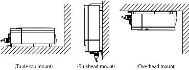
2.3Planning the Installation
When planning the installation of your RAY230/E, the following conditions should be considered to ensure dependable and trouble-free operation.
Mount the Base Station Transceiver, Handset cradle(s), and External Speaker(s) using the Mounting Templates provided.
The Base Station Transceiver is designed to be mounted horizontally or vertically on a flat bulkhead below decks. Select a location that is nonmetallic, dry, protected, well-ventilated, and free from high operating temperatures and excessive vibration. Provide sufficient space behind the transceiver to allow for proper cable connections to the rear panel connectors. Locate the transceiver as near as possible to the power source yet as far apart as possible from any devices that may cause interference such as motors, generators, and other on board electronics. The transceiver should be protected from prolonged direct exposure to rain and salt spray.
The transceiver is NOT designed to be mounted in engine compartments. Do NOT install the transceiver in a location where there may be flammable vapors (such as in an engine room or compartment, or in a fuel tank bay), water splash or spray from bilges or hatches, where it is at risk from physical damage from heavy items (such as hatch covers, tool boxes, etc.), or where it might be covered by other equipment.
Locate the Base Station transceiver and Handset at least 3 feet from the antenna.
Mount the primary handset and cradle such that they allow easy access from the location where the ship is normally navigated. By FCC law, the primary handset should be located in the wheel house or in a room adjacent to the wheel house.
Figure 2-1 Typical Mounting Methods
Installation |
2-3 |
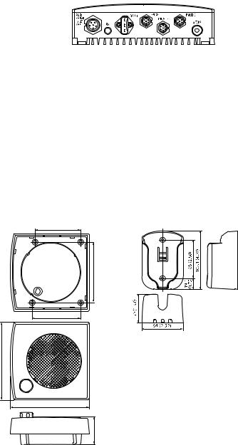
Base Station Transceiver
197 (7.76)
1.78 (7.04)
67 (2.63) |
200 (7.87) |
|
228 (8.98) |
External Speaker Unit |
Cradle Unit |
|
65 (2.56) |
|
84 (3.31) |
70 (2.76) |
110 (4.33)
114 (4.49)
25 (.98)
Figure 2-2 Outline and Mounting Dimensions
All dimensions are shown in millimeters and (inches)

2-4 |
Installation |
2.4Electrical Connections
2.4.1DC Power and Hailer/NMEA Cable Connections
The 6-foot-long power cable is a multipurpose assembly containing three wire-pairs for connections to DC power, NMEA input, and the Hailer Horn speaker. Connections to the 6-pin connector are as follows:
Wire Color |
Function |
Connects to |
RED |
Power + |
Ship's 13.2 VDC power |
BLACK |
Power – |
|
|
|
|
YELLOW |
Hailer + |
Hailer Horn speaker |
GREEN |
Hailer – |
|
|
|
|
WHITE |
NMEA + |
Input from position source (GPS) |
BLACK |
NMEA – |
|
The RED (+) power wire contains a 10 amp in-line fuse.
Figure 2-3 Power/Hailer/NMEA Cable and 6-pin Connector
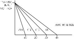
In most cases the length of the power cable should be adequate enough to reach the DC power source. If additional wire length is required, the cable can be extended by adding more cable as necessary. However, for power cable runs longer than 15 feet, larger wire diameter size should be used to prevent voltage line loss.
Installation |
2-5 |
Figure 2-4 Power Cable Length
Your RAY230/E radio should be connected to the nearest primary source of ship's DC power. A typical source may be a circuit breaker on the power panel or a fuse block near the unit. When connecting to either of these sources, the circuit breaker or other in-line fuse should be rated at 10 amps.
It is recommended that lugs be used to connect the power cable to the DC supply and the lug connections should be both crimped and soldered. This is very important in order to ensure adequate current draw to the equipment. If an insufficient connection is made to the power source, the unit may not work properly. The connection terminal should be clean, with no sign of corrosion.
The RED (+) wire is connected to the positive terminal of the power source. The BLACK (–) wire is connected to the negative (ground) of the power source. Should the power connections be inadvertently reversed, the unit will not power up but no damage will occur. Simply check the polarity with a VOM (Voltage/Ohm Meter) and reconnect observing correct polarity. If the fuse ever needs replacement, be sure to use the same type and rating.
2.4.2Hailer Cable Connections
The YELLOW (+) wire and GREEN (–) wire are used for connecting the RAY230/RAY230E to a Hailer Horn speaker, such as the Raymarine M95435 (Refer to Figure 2-3).
10 watts of audio output power are provided for an external 4 ohm speaker. Connect the YELLOW (+) wire and GREEN (-) wire to the speaker observing polarity as it is marked on the speaker. When connected, the hailer horn speaker will operate in Hailer or Fog modes.
CAUTION: To avoid damage to the radio, DO NOTconnect the Hailer GREEN (–) wire to the HailerYELLOW (+) wire.Also, DO NOT connect the Hailer GREEN (–) wire to the Power BLACK (–) wire.
2-6 |
Installation |
2.4.3NMEA Data
The RAY230/E accepts NMEA0183 data from a position determining device (GPS, etc.) to provide the Latitude and Longitude position information that is transmitted during a DSC Distress Call.
Connect the input(s) of the positioning device to the white (NMEA+) and black (NMEA-) wires in the Power/Hailer/NMEA cable.
An example of how to connect the NMEA cables and power supply using a suitable connector block is shown in the diagram below. For specific instructions how to connect your particular GPS, please refer to the handbook that came with that device.
Note: For non-differential GPS, all return connections (-) must be tied to a common ground reference.
Red
+12 V
Yellow
+ NMEA Data (white)
Black
-- NMEA Data (black)
0V
Figure 2-5 Sample GPS Connections to NMEA
2.4.4Using the SeaTalk Auxiliary Junction Box
If installed, it may be convenient to connect the RAY230/E using the SeaTalk auxiliary junction box. This junction box enables the SeaTalk bus, power, and GPS to be connected.
If power is not already available (via another SeaTalk instrument), the junction box can be used to apply power to the SeaTalk bus for other applications. The junction box may also be used for connecting an NMEA GPS system.

Installation |
2-7 |
The junction box includes:
•SeaTalk cable and connector to attach to display unit
•Power cable to connect to 12 V power (if required)
•Input connections to connect SeaTalk cable from external equipment
•Spare connections for another instrument
The illustration below shows how to connect the junction box.
|
|
|
To GPS |
|
|
|
Power Out: 1 & 2 |
|
|
|
Power In: 1 & 3 |
To Radio’s |
|
|
|
SeaTalk |
|
|
|
Socket |
|
|
|
0 VDC (return) |
|
|
|
To Ship’s |
|
|
Spare |
Power Supply |
|
|
Input |
+VDC (fused) |
|
|
|
Cable |
Core |
Terminal |
Function |
SeaTalk |
Black (screen) |
1 |
0V |
|
Red |
2 |
+12v |
|
Yellow |
3 |
SeaTalk |
Power |
Black (screen) |
1 |
0V |
|
Red |
2 |
+12V |
GPS |
Black (screen) |
1 |
0V |
|
Red |
2 |
+12V |
|
Yellow |
3 |
SeaTalk |
Figure 2-6 SeaTalk Junction Box Connections
2.4.5Antenna Connections
Your coaxial VHF antenna cable connects to the RAY230/E antenna cable on the rear panel using a PL259 VHF type connector. Your VHF antenna cable can be cut to length but the overall cable length can be critical to performance. If you are uncertain, contact a professional installer or call Raymarine Customer Service. If a longer cable length is required, RG-58 (50 ohm) coaxial cable or equivalent cable can be used for runs up to a maximum of 50 feet. If the distance required is even greater, we recommend using low loss RG-213 or equivalent cable for the entire run to avoid excessive losses in power output.
If the antenna RF connector is likely to be exposed to the marine environment, a protective coating of grease (Dow Corning DC-4 or similar) can be applied to the connector before connecting it to the radio. Any other extensions or adapters in the cable run should also be protected by silicon grease and then wrapped with a waterproofing tape.
2-8 |
Installation |
2.4.6Antenna Mounting Suggestions
The best radio in the world is useless without a quality antenna and good location. Mounting the VHF antenna properly is very important because it will directly affect the performance of your VHF radio. A VHF antenna designed for marine vessels should be used.
•Since VHF transmission is essentially line-of-sight, mount the antenna at the highest possible location on the vessel and free of obstruction to obtain maximum range.
•If you must extend the length of the coaxial cable between the antenna and the radio, use a coaxial cable designed for the least amount of power loss over the entire cable length.
2.4.7Grounding
It is good marine practice to properly ground your VHF radiotelephone, as well as all other electronic equipment, to the ship's ground system.
One of the mounting tabs on the edge of the base station transceiver has been designated for this purpose. See Figure 2-7 below. After the base station has been mounted, you should ground the unit by attaching a wire to the screw inserted through the tab labeled “GND”. Then connect this wire to the nearest ship's ground connection point. The recommended wire to be used for such grounding is #10 AWG.
GND
Mounting Tab |
Mounting Tab |
Figure 2-7 Typical Grounding Method

Operations |
3-1 |
Section 3 |
Operations |
3.1Introduction
The RAY230 has the capability to transmit and receive on all available US, Canadian, and International Marine VHF radiotelephone channels. The RAY230E can transmit and receive on all available International and US Marine VHF radiotelephone channels. There are channels that are FCC approved but may only be used by authorized stations for specific purposes, depending on the type of vessel (commercial or non-commercial.) Refer to Section 5.3, which lists all marine VHF channels available in your RAY230/RAY230E for US, International and Canadian radiotelephone use. You should familiarize yourself with these tables to ensure you use the proper channels.
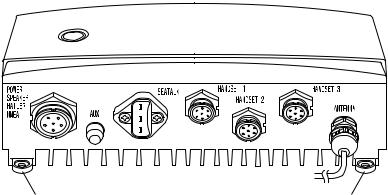
Figure 3-1 Layout of Controls

3-2 |
Operations |
3.2Controls and LCD Display
3.2.1Controls
INDV key
Switches to the DSC Individual Ships Call mode for initiating ship-to- ship or ship-to-shore calls using a specific MMSI number. Descriptions of these operations appear below in sections 3.5.26.1 and 3.5.26.2.
Note: An MMSI number is required to operate the DSC equipment in this radio. You can program the MMSI number yourself one time only using the Menu Operation described in section 3.5.30.4.2 or you can have your Raymarine dealer program the number for you.
ALL SHIP key
Switches to the All Ships Call mode for Safety and Urgency transmissions. Descriptions of subsequent operations appear below in section 3.5.26.5 Transmitting All Ships Call.
!SQ UP/DOWN (SCROLL) key
Increases or decreases the squelch sensitivity. Pressing the UP
key increases the squelch, while the DOWN key decreases it. The number of segments in the SQ bar graph on the LCD display will increase or decrease accordingly. This key is also used as a scroll key for selecting menu items and other settings, as described below.
" VOL UP/DOWN key
Changes the sound volume of the handset. Pressing the UP key increases the volume, while the DOWN key causes it to decrease. The number of segments in the VOL bar graph on the LCD display will increase or decrease accordingly.
#16/9/POWER key (RAY230 US version only)
Switches between the Working Channel and the Priority Channel. Pressing and holding the key for 2 seconds alternates the Priority Channel between channel 9 and channel 16. When the transceiver’s main power switch is turned on, this key is also used to power the system ON or OFF.
$16/POWER key (RAY230E European version only)
Switches between the Working Channel and Channel 16 (the Priority Channel). When the transceiver’s main power switch is turned on, this key is also used to power the system ON or OFF.

Operations |
3-3 |
%MON/TRI key
Starts the Dual-Watch monitor mode. Pressing the FUNC key followed by the MON/TRI key initiates the Tri-Watch monitor mode.
&1/MEM key
This key inputs the number 1. When an alphanumeric response is appropriate, this key alternates between entering a 1 and a space. If the channel number indicated on the LCD display is not currently stored in memory, pressing the FUNC key followed by the 1/MEM key enters that channel number into memory. If the currently indicated channel has already been stored, pressing the FUNC key followed by the 1/MEM key deletes that channel from memory.
'2/SCAN key
This key inputs the number 2. When an alphanumeric response is appropriate, each press of this key alternately inputs the characters 2, A, B, then C. Pressing the FUNC key followed by the 2/SCAN key toggles Scan mode ON or OFF. Scan mode is described below in Section 3.5.21.
3/CELL key
This key inputs the number 3. When an alphanumeric response is appropriate, each press of this key alternately inputs the characters 3, D, E, then F. Pressing the FUNC key followed by the 3/CELL key connects the handset with any auxiliary communication equipment with DTMF interface (RAYCOM Cellular, Mini-M, etc.) connected to the AUX port at the rear of the transceiver. See section 3.5.19.
4/INT key (RAY230 only)
This key inputs the number 4. When an alphanumeric response is appropriate, each press of this key alternately inputs the characters 4, G, H, then I. Pressing the FUNC key followed by the 4/INTkey alternates the frequency groups from US mode to International mode to Canadian mode.
4/US key (RAY230E only)
This key inputs the number 4. When an alphanumeric response is appropriate, each press of this key alternately inputs the characters 4, G, H, then I. Pressing the FUNC key followed by the 4/US key alternates the frequency groups between US mode and International mode.
Note: Access to the US frequency group is only available with a software upgrade from your dealer. Otherwise this feature is disabled.

3-4 |
Operations |
! 5 key (RAY230 only)
This key inputs the number 5. When an alphanumeric response is appropriate, each press of this key alternately inputs the characters 5, J, K, then L.
" 5/PRIV key (RAY230E only)
This key inputs the number 5. When an alphanumeric response is appropriate, each press of this key alternately inputs the characters 5, J, K, then L. Pressing the FUNC key followed by the 5/PRIV key switches to the Private Channel mode. To select the desired Private Channel, press the FUNC key followed by the 5/PRIV key, then input the number key(s) corresponding to the desired channel number and press ENT.
# 6/WX key
This key inputs the number 6. When an alphanumeric response is appropriate, each press of this key alternately inputs the characters 6, M, N, then O. Pressing the FUNC key followed by the 6/WX key alternates between the Working Channel and the Weather Channel. For the RAY230E European model, this operation is valid only in US frequency mode.
$ 7/ D/L key
This key inputs the number 7. When an alphanumeric response is appropriate, each press of this key alternately inputs the characters 7, P, Q, R, then S. Pressing the FUNC key followed by the 7/D/L key toggles between full receiver sensitivity (distant mode) and attenuated receiver sensitivity (local mode). Local mode is used in high traffic areas to decrease unwanted reception. While in local mode (receiver is desensitized), the DESENS indicator appears in the LCD display.
% 8 key (RAY230 only)
This key inputs the number 8. When an alphanumeric response is appropriate, each press of this key alternately inputs the characters 8, T, U, then V.
& 8/ M-CALL key (RAY230E only)
This key inputs the number 8. When an alphanumeric response is appropriate, each press of this key alternately inputs the characters 8, T, U, then V. Pressing the FUNC key followed by the 8/M-CALL key starts Multi-Call mode. If the key is pressed during Multi-Call mode, the operation returns to normal mode.

Operations |
3-5 |
' 9/ 1/25 key
This key inputs the number 9. When an alphanumeric response is appropriate, each press of this key alternately inputs the characters 9, W, X, Y, and then Z. Pressing the FUNC key followed by the 9/1/25 key alternates the transmission power between 1W and 25W.
*/HAIL key
This key inputs an asterisk (*). Pressing the FUNC key followed by the */HAIL key initiates the Hailer mode, which enables a Hailer Horn speaker to be used as a loud speaker or a directional microphone. Pressing the FUNC key followed by this key during Hailer mode returns operation to normal mode.
0/IC key
This key inputs the number 0. Pressing the FUNC key followed by the 0/IC key starts Intercom mode, which enables conversation between handsets. Pressing the FUNC key followed by this key during Intercom mode returns operation to normal mode.
#/FOG key
This key inputs the # character. Pressing the FUNC key followed by the #/FOG key initiates the Fog Alert mode, which enables a Hailer Horn speaker to sound several types of automatic or manual alert tones. Pressing the FUNC key followed by this key during Fog mode returns operation to normal mode.
!ENT/MENU key
This key performs the Enter function. It is used to confirm and implement an input action. Pressing the FUNC key followed by the ENT/MENU key initiates the Menu mode.
"CLR/LOG key
Depending on when it is used, this key exits the current mode and reverts to the last used mode or normal operation. This key also can be used to clear any alphanumeric inputs one at a time in the order that they were entered. Pressing the FUNC key followed by CLR/LOG key initiates the Digital Selective Calling (DSC) Log. Pressing the key during logging returns operation to normal mode.
#FUNC/DIM key
Initiates the Function mode and activates the FUNC indicator in the LCD display. The next key pressed determines the function selected. (See above key descriptions.) Pressing this key twice starts Dimmer mode, which reduces the brightness of LCD's backlight.
3-6 |
Operations |
$Channel UP/ DOWN switch
Pressing this switch during normal operation changes the channel number UP or DOWN.
%PTT (Press-to-Talk) switch
Pressing this switch during normal operation places the radio in Transmit mode and displays the TX indicator in the LCD. When the switch is pressed in various function modes, the assigned operation is initiated.
Note: After 5 minutes of continuously holding the PTT switch, the radio will automatically stop transmitting. To begin transmitting again, release the PTT and depress again.
&DISTRESS switch
This switch is located under the small door labeled DISTRESS on the back of the handset. Pressing and holding this switch for 4 seconds selects Distress Signal Call mode. Subsequent operations are described in section 3.5.26.7.
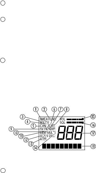
3.2.2LCD Display
The following describes the functional characters on the RAY230/RAY230E Handset's LCD.
Figure 3-2 LCD Display Layout
NMEA indicator
Displayed when the radio receives valid SeaTalk or NMEA position data. If the data is invalid or no data is received for a period of time, the indicator disappears.

Operations |
3-7 |
FUNC indicator
Displayed when the FUNC key is pressed. Disappears when another key is pressed, or after no other key is pressed for a period of time.
!WX indicator
Displayed while in Weather Channel mode. For the RAY230E, this indicator only appears in the US frequency mode, if this feature has been activated.
"TX indicator
Displayed while transmitting.
#CAN indicator (RAY230 only)
Displayed when the Canadian frequency group is selected.
$US indicator
Displayed when the US frequency group is selected.
%DESENS indicator
Displayed during the desensitized receiving (local) mode.
&INT indicator
Displayed when the International frequency group is selected.
'1W indicator
Displayed when the transmission power of 1W is selected with the 9/ 1/25 key or when a low power channel is selected.
MULTI indicator (RAY230E only)
Displayed while the channel stored in Multi-Call memory is displayed.
MEM indicator
Displayed while the channel stored in memory is displayed. This indicator flashes before the start of the memory scan operation.
SCAN indicator
Displayed during Scan mode. If channels have been stored in memory, this indicator will be flashing before the start of Scan mode.
!
"
ATIS indicator (RAY230E only)
Displayed when the ATIS (automatic identification transmission) feature is turned on (via Menu mode).
DSC indicator
Displayed when in a Digital Selective Calling (DSC) call mode, DSC log, or the DSC menu.
 Loading...