


 Loading...
ST60 Rudder
AngleIndicator
Instrument
Owner’s
Handbook
Document number: 81123-4
Date: 1 April 2004
Raymarine, ST60 and SeaTalk are trademarks of Raymarine Limited
© Handbook contents copyright Raymarine Limited 2004

Preface i
Preface
Important information
Safety notices
WARNING: Product installation & operation
This equipment must be installed and operated in accordance with the Raymarine instructions provided. Failure to do so could result in personal injury, damage to your boat and/or poor product performance.
WARNING: Electrical safety
Make sure you have switched off the power supply before you start installing this product.
WARNING:
Although we have designed this product to be accurate and reliable, many factors can affect its performance. Therefore, it should serve only as an aid to navigation and should never replace commonsense and navigational judgement. Always maintain a permanent watch so you can respond to situations as they develop.
EMC conformance
All Raymarine equipment and accessories are designed to the best industry standards for use in the recreational marine environment.
The design and manufacture of Raymarine equipment and accessories conform to the appropriate Electromagnetic Compatibility (EMC) standards, but correct installation is required to ensure that performance is not compromised.
Handbook information
To the best of our knowledge, the information in this handbook was correct when it went to press. However, Raymarine cannot accept liability for any inaccuracies or omissions it may contain.
In addition, our policy of continuous product improvement may change specifications without notice. Therefore, Raymarine cannot accept liability for any differences between the product and the handbook.
ii |
ST60 Rudder Angle Indicator Instrument Owner’s Handbook |

Preface |
|
iii |
Contents |
|
|
Preface ...................................................................................................................... |
|
i |
Important information ..................................................................................... |
i |
|
|
Safety notices .......................................................................................... |
i |
|
EMC conformance ................................................................................... |
i |
|
Handbook information ............................................................................ |
i |
Contents................................................................................................... |
iii |
|
Introduction .................................................................................................... |
v |
|
Data inputs ..................................................................................................... |
v |
|
|
SeaTalk ................................................................................................... |
v |
|
Using with SeaTalk Autopilot .......................................................... |
vi |
|
Stand alone operation ........................................................................... |
vi |
Options .......................................................................................................... |
vi |
|
|
Linear transducer .................................................................................. |
vi |
|
Mounting .............................................................................................. |
vi |
Parts supplied ................................................................................................ |
vi |
|
Chapter 1: Operation ............................................................................................ |
1 |
|
1.1 |
Getting started ....................................................................................... |
1 |
|
Displayed information ............................................................................ |
1 |
|
Operation with other instruments .......................................................... |
1 |
1.2 |
Normal use ............................................................................................. |
1 |
|
Display illumination ............................................................................... |
2 |
1.3 |
Remote control ...................................................................................... |
2 |
Chapter 2: Maintenance & Troubleshooting ..................................................... |
3 |
|
2.1 |
Maintenance .......................................................................................... |
3 |
|
Servicing and safety ............................................................................... |
3 |
|
Instrument ............................................................................................. |
3 |
|
Transducer ............................................................................................. |
3 |
|
Cabling ................................................................................................... |
4 |
2.2 |
Troubleshooting ..................................................................................... |
4 |
|
Preliminary procedures .......................................................................... |
4 |
2.3 |
Fault location ......................................................................................... |
4 |
|
Technical support ................................................................................... |
5 |
|
World wide web ............................................................................... |
5 |
|
Telephone help line .......................................................................... |
5 |
|
Help us to help you ........................................................................... |
5 |
Chapter 3: Installation ......................................................................................... |
7 |
|
3.1 |
Planning your installation ...................................................................... |
7 |
|
Site requirements ................................................................................... |
7 |
|
Transducer ....................................................................................... |
7 |

iv |
ST60 Rudder Angle Indicator Instrument Owner’s Handbook |
|
|
Instrument ........................................................................................ |
7 |
|
EMC installation guidelines .................................................................... |
8 |
|
Suppression ferrites .......................................................................... |
9 |
|
Connections to other equipment ...................................................... |
9 |
3.2 |
Procedures ............................................................................................. |
9 |
|
Unpacking ............................................................................................ |
10 |
|
Fitting the instrument ........................................................................... |
10 |
|
Surface mounting ........................................................................... |
10 |
|
Flush mounting .............................................................................. |
11 |
|
Fitting the low-profile bezel ...................................................... |
11 |
|
Flush mounting procedure ....................................................... |
13 |
|
Bracket mounting ........................................................................... |
14 |
|
Fitting transducers ................................................................................ |
14 |
|
Rotary Rudder Reference Transducer .............................................. |
14 |
|
Mounting ................................................................................. |
15 |
|
Connecting to the tiller ............................................................. |
15 |
|
Linear Rudder Reference Transducer .............................................. |
17 |
|
Mounting ................................................................................. |
17 |
|
Transducer cabling ......................................................................... |
18 |
|
General .................................................................................... |
18 |
|
Running the cable .................................................................... |
18 |
|
Connecting the instrument ................................................................... |
19 |
|
Introduction ................................................................................... |
19 |
|
Signal connections ......................................................................... |
19 |
|
Power supply connections .............................................................. |
20 |
|
SeaTalk systems ....................................................................... |
20 |
|
Stand alone instruments .......................................................... |
20 |
Chapter 4: Calibration ........................................................................................ |
23 |
|
4.1 |
Introduction .......................................................................................... |
23 |
|
EMC conformance ................................................................................ |
23 |
4.2 Rudder angle offset adjustment ........................................................... |
23 |
|

Preface |
v |
Introduction
Thank you for purchasing a Raymarine product. We are sure your ST60 instrument will give you many years of trouble-free operation.
This handbook describes how to install and use the Raymarine ST60 Rudder Angle Indicator instrument. This instrument gives a continuously updated (real time) display of your vessel’s rudder angle.
The ST60 Rudder Angle Indicator instrument is constructed in a rugged weather proofed case. It provides a sensitive and stable analog display, to deliver accurate information under even the most demanding conditions.
-3 D4303
Data inputs
The instrument can be used either as a stand-alone unit, or as part of an integrated SeaTalk instrumentation system.
SeaTalk
When connected to SeaTalk, the ST60 Rudder Angle Indicator can operate as a repeater to any Raymarine SeaTalk autopilot, or provide rudder position information to another rudder angle instrument.
SeaTalk enables a number of compatible instruments to be interconnected and operate as a single, integrated navigational system.
Power and data in a SeaTalk system are fed via a single cable, so that instruments be connected by plugging them into the network. SeaTalk is flexible enough to adapt to any number of compatible instruments without requiring a central
vi |
ST60 Rudder Angle Indicator Instrument Owner’s Handbook |
processor. SeaTalk can also communicate with non-SeaTalk equipment, using the internationally-accepted National Marine Electronics Association (NMEA) protocol.
In a SeaTalk system, each instrument can be either a master or dedicated repeater unit. A master instrument is directly connected to a transducer (the device that provides the raw data) and has control of all other equipment on the SeaTalk network. A slave instrument is not directly connected to a transducer but repeats information provided by other equipment in the SeaTalk network.
Using with SeaTalk Autopilot
If the ST60 Rudder Angle Indicator is part of a system which includes a SeaTalk autopilot, the rudder reference transducer is connected to the autopilot and the Rudder Angle Indicator operates in repeater mode, i.e. as a slave display to the autopilot, with the autopilot data displayed using the Rudder Angle Indicator analog pointer.
Stand alone operation
In Stand alone operation, the ST60 Rudder Angle Indicator is connected only to a rudder reference transducer and does not display information from, or provide information to, any other instruments.
Options
Linear transducer
A Linear Rudder Reference Transducer option is available for use with ‘bullhorn’ type outboard installations.
Mounting
If you do not want to surface mount your ST60 instrument, options are available for:
•Flush mounting. If you have ordered the flush mounting option a low-profile bezel and four fixing screws are also provided.
•Bracket mounting.
Parts supplied
Unpack your ST60 instrument and check that the following items are present:
•Item 1, ST60 Rudder Angle instrument with standard bezel.
•Item 2, Fixing studs (2).

Preface |
vii |
•Item 3, Thumb nuts (2).
•Item 4, Gasket.
•Item 5, Rotary Rudder Reference transducer with fittings (not illustrated).
•Item 6, SeaTalk interconnection cable.
•Item 7, Power cable.
•Item 8, Instrument Cover.
•Item 9, Owner’s Handbook. The Warranty document andmounting templates are included in this Handbook.
Spare spade terminals are also provided, to re-terminate the transducer cable if it has to be cut to facilitate installation.
Note: The above packing list is for an ST60 Rudder Angle Indicator system. Where an instrument is purchased separately, a transducer is not included.
2 |
3 |
2 |
3 |
1 |
4 |
6 |
|
|
5 |
7 |
|
|
ST60 |
|
Rudder |
|
Angle |
|
Instrument |
|
Owner's |
|
Handbook |
8 |
9 |
|
D4443-4 |
viii |
ST60 Rudder Angle Indicator Instrument Owner’s Handbook |
Chapter 1: Operation |
1 |
Chapter 1: Operation
1.1 Getting started
This handbook describes how to operate, maintain and install the Raymarine ST60 Rudder Angle Indicator Instrument. The instrument provides a real-time indication of rudder position as determined by the associated Rudder Reference Transducer.
CAUTION: Calibration requirement
The ST60 Rudder Angle Indicator instrument is calibrated to factory (default) settings when first supplied. To ensure optimum performance on your boat, this product must be calibrated before use. Do NOT use the product until it has been calibrated using the procedures in Chapter 4, Calibration.
Displayed information
The ST60 Rudder Angle Indicator pointer shows the rudder position in real-time. The instrument scale range gives an expanded indication from -40° to +40° about zero.
Operation with other instruments
When the ST60 Rudder Angle Indicator is connected to an operational autopilot via SeaTalk, the instrument acts as slave to the autopilot, which receives data from the Rudder Angle Indicator Transducer and passes the information via the SeaTalk bus.
1.2 Normal use
As the ST60 Rudder Angle Indicator operates in real time, very little operator action is necessary during normal use except to observe the instrument as required to ascertain the rudder angle.
Note: If rudder angle information is not available on the SeaTalk bus, the analog pointer oscillates ±10° about the top of the dial.
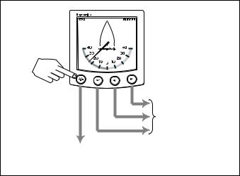
The  key is the only key used during normal operation (see Key functions illustration). The set, < and > keys are reserved for calibration mode, see Chapter 4, Calibration. All key presses called for in this handbook are momentary, unless otherwise stated.
2 |
ST60 Rudder Angle Indicator Instrument Owner’s Handbook |
Used for calibration
(see Chapter 4, Calibration )
Press for 1 second
to adjust illumination level
Key functions |
D4425-2 |
Display illumination
When the instrument is first powered up, the display illumination is set to its lowest (courtesy) level, to facilitate initial access to the keys.
To adjust the level of display illumination:
1.Hold down the  key for approximately 1 second, to enter the illuminationadjust mode.
2.There are four preset illumination levels from a courtesy level to full bright-
ness. Momentarily press the  key to cycle through these levels until you reach the level you want. The selected level is transmitted to all other instruments on the SeaTalk bus.
3.Press any other key to leave the illumination-adjust mode.
Note: The display will return to normal operation 7 seconds after the last key press.
1.3 Remote control
The ST60 Rudder Angle Indicator does not support the SeaTalk remote control facility. You can only control the instrument with the front panel keys.
Loading...