


E120

E-Series
Networked Display
Installation Manual
Document Number: 87043_2
Date: March 2006

Trademarks and registered trademarks
Autohelm, HSB, Raymarine, RayTech, RayTech Navigator, Sail Pilot,
SeaTalk and Sportpilot are registered trademarks of Raymarine
Limited. Apelco is a registered trademark of Raymarine Holdings
Limited (registered in all major marketing territories).
AST, Autoadapt, Auto GST, Autoseastate, Autotrim, Bidata, Marine
Intelligence, Maxiview, On Board, Raychart, Raynav, Raypilot, Raystar,
ST40, ST60, Seaclutter, Smart Route, Tridata and Waypoint Navigation
are trademarks of Raymarine Limited.
Navionics is a registered trademark of Navionics Company, Italy. All
other product names are trademarks or registered trademarks of their
respective owners.
Copyright: ©Raymarine 2006
Important Information i
Important Information
Intended use
This handbook provides information and instructions to assist in planning and
installing your Raymarine E-Series Networked Display, together with information that
will be useful when you are connecting the E-Series Display to other equipment.
In order to obtain the best results in operation and performance, please read this
handbook thoroughly.
Safety notices
WARNING:Navigation aid
This product is intended to be used as an aid to navigation. Its
accuracy can be affected by many factors, including
equipment failure or defect, environmental conditions and
incorrect handling or use. It is the Users responsibility to
exercise common prudence and navigational judgement. This
device should not be relied upon as a substitute for such
prudence and judgement.
WARNING:Product installation
This equipment must be installed in accordance with the
instructions in this handbook. Failure to do so could result in
poor product performance, personal injury and/or damage to
the vessel.
WARNING:Electrical safety
Make sure the power supply is switched off before making
any electrical connections.
WARNING:Electromagnetic energy
The radar scanner transmits electromagnetic energy. Ensure
that the scanner has been installed according to the
recommendations given in the relevant scanner handbook.
WARNING:Fishfinder sounder module
Removing the transducer cable from the fishfinder sounder
module whilst it is switched on can cause sparks and may
damage the unit. Only remove the transducer cable after
power has been switched off. Ensure that the sounder module
is mounted where it is well ventilated and in an area free from
flammable vapors.

ii E-Series Networked Display Installation Manual
CAUTION: Radar Scanners, Cables & Installation
Information on radar scanners, cables and their installation contained in
this handbook supersedes that contained in the Pathfinder Radar
Scanner Handbook, Document No. 81154_8, dated 12th January 2005.
CAUTION: Front cover clip-on installation
After installing the front cover clip-on, check that all buttons and soft
keys have passed through completely and are free to operate correctly.
CAUTION: Global Positioning System Antenna
Do not connect or disconnect the GPS antenna from the display unit
whilst power is switched on. Doing this may result in irreparable damage
CAUTION: Water Ingress
To prevent the ingress of water and damage to the display:
• Ensure that the chart card door is firmly closed. This can be confirmed
by an audible click.
• Do not remove the SeaTalk High Speed blanking plug from the rear of
the display until such time as you are ready to connect the cable.
• Ensure that the SeaTalk High Speed cable is clicked into place AND
then turned to lock it.
CAUTION: Connections into display
Ensure power is switched off prior to connecting or removing any cables
into the rear of the display. Failure to do so can cause irreparable
damage.
CAUTION: CompactFlash Card Installation
When installing CompactFlash cards ensure that the card is being fitted
the correct way round. DO NOT try and force the card into position as this
may result in irreparable damage to the card.
CAUTION: CompactFlash Cards
Removing the CompactFlash card whilst information is being written to
it may cause damage to the card and loss of all data. A warning on the
display indicates when writing is in progress.
CAUTION: Chart and CompactFlash card damage
DO NOT use a metallic instrument such as a screwdriver or pliers to help
you remove a card, as doing this can cause irreparable damage to the
card and/or display unit.

Important Information iii
EMC Conformance
All Raymarine equipment and accessories are designed to the best industry standards
for use in the recreational marine environment.
The design and manufacture of Raymarine equipment and accessories conform to the
appropriate Electromagnetic Compatibility (EMC) standards, but correct installation is
required to ensure that performance is not compromised.
Handbook information
To the best of our knowledge, the information in this handbook was correct when it
went to press. However, Raymarine cannot accept liability for an inaccuracies or
omissions it may contain.
In addition, our policy of continuous product improvement may change specifications
without notice. Therefore Raymarine cannot accept liability for any differences
between the product and the handbook.
Disposal
Waste Electrical and Electronic Equipment (WEEE) Directive
The WEEE Directive requires the recycling of waste electrical and electronic
equipment. Whilst the WEEE Directive does not apply to some of Raymarine’s
products, we support its requirements as part of our environmental policy and
we ask you to be aware of how you should dispose of this product.
The crossed-out wheelie bin symbol found on our products signifies that it should not
be disposed of in general waste or landfill.
Please contact your local dealer, national distributor or Raymarine Technical Services
for information on product disposal.

iv E-Series Networked Display Installation Manual

1
Contents
Chapter 1: Preparation for installation ..................................................................3
1.1 General information ............................................................................................. 3
Contents of this pack .......................................................................................3
Dimensions ..................................................................................................... 4
Accessories and spares ................................................................................... 5
1.2 Planning the installation .......................................................................................6
EMC Installation Guidelines ............................................................................ 6
Locating the display ........................................................................................ 7
EMC Conformance .......................................................................................... 7
Chapter 2: System Integration .................................................................................9
2.1 What is System Integration? ................................................................................. 9
What is SeaTalk? ............................................................................................. 9
What is NMEA? .............................................................................................10
2.2 Compatibility ...................................................................................................... 11
Radar Scanners .............................................................................................11
Digital Sounder Module ................................................................................ 11
Engines .........................................................................................................11
Media storage cards ......................................................................................12
2.3 Functionality .......................................................................................................12
Data or equipment required for applications/functions .................................13
2.4 Integrating an E-Series display ............................................................................14
Single display system .................................................................................... 15
Networking E-Series Displays ........................................................................16
A typical two node system incorporating two displays .................................. 17
An example of a three (or more) node system ...............................................18
Connecting your E-Series display to a SeaTalk2 Keyboard .............................19
Chapter 3: Installation .............................................................................................21
3.1 Mounting the display .......................................................................................... 21
Trunnion mount ............................................................................................ 21
Flush mount .................................................................................................. 23
Attaching the front cover clip-on ................................................................... 24
Removing the front cover clip-on .................................................................. 25

2 E-Series Installation Manual
3.2 Cables .................................................................................................................26
Siting and securing cables .............................................................................26
Connecting cables ......................................................................................... 26
Cable types ................................................................................................... 28
Chapter 4: Commissioning the system .................................................................37
4.1 Introduction ........................................................................................................37
4.2 Pre-start checks .................................................................................................. 37
4.3 Initial power on procedure .................................................................................. 38
4.4 Testing and checks .............................................................................................. 39
Radar checks and alignment .........................................................................39
GPS checks .................................................................................................... 41
Heading data checks .....................................................................................42
Chart application checks ...............................................................................42
Fishfinder application tests ...........................................................................43
Video tests .................................................................................................... 43
SeaTalkhs network switch connection tests .................................................. 44
Setting up the NMEA for AIS or Navtex .........................................................44
Instrument data tests ....................................................................................44
Running AIS ..................................................................................................45
Weather application tests .............................................................................45
4.5 Advanced Settings ..............................................................................................46
Adjusting the settings ................................................................................... 46
Chapter 5: Troubleshooting ....................................................................................49
5.1 How can I troubleshoot my Display? ................................................................... 49
5.2 How can I get Technical Support? ....................................................................... 50
World wide web ............................................................................................50
Help us to help you ........................................................................................ 50
How can I contact Raymarine in the US? .......................................................51
How can I contact Raymarine in Europe? ......................................................52
Chapter 1: Preparation for installation 3
Chapter 1: Preparation for installation
1.1 General information
Contents of this pack
The E- Series (E80 or E120) Networked Display pack contains the following items:
Part name
Networked display E02011 E02013
Front cover clip-on R58183 R58194
Sun cover R58184 R58195
Cables (all 1.5m):
• Power
• NMEA 0183
• SeaTalk/Alarm out
• SeaTalk High Speed Network
• Video-in composite cable
Part no.
E80 E120
R89005
R08004
E55054
E55049
E55057
Cable splice (x3)
For trunnion mounting the display:
• Trunnion bracket
• Trunnion bracket knobs (x2)
•Bolt M6 x 50 (x5)
•Washer M6 penny (x5)
•Nut M6 Nylok (x5)
For flush mounting the display:
• Panel seal
• Bolts - M4 x 40 hexhead (x4)
•Nuts - M4 (x4)
• Washers - M4 (x4)
• Spring washers - M4 (x4)
Document wallet containing:
• Reference Manual
• Installation Manual
• Operating Guide
• Flush mount template
Cleaning cloth
Note:
To prevent damage, unpack the display carefully. Save the carton and packing, in case
R58204
R08001
R58182 R58193
81244_2
87043_2
86114_2
87044_1
the unit has to be returned for service.
R58205
R08001

4 E-Series Installation Manual
Dimensions
The dimensions for your E-Series display are:
E80 Display
Weight 4.18 kg
(9lbs 3oz)
PAGE
ACTIVE
WPTS
MOB
DATA
283 mm (111/8 in)
7
315 mm (12
/16 in)
MENU
OUT
RANGE
IN
CANCELOK
/8 in)
/8 in)
3
7
212 mm (8
252 mm (9
3
9.5 mm (
/8 in)
123 mm (4
154 mm (61/16 in)
7
/8 in)
Note: All imperial measurements are approximate.
E120 Display
356 mm (14 in)
388 mm (151/4 in)
Note: All imperial measurements are approximate.
182 mm (73/16 in) clearance
D7206-2
Weight 7.35 kg
(16lb 3oz)
PAGE
ACTIVE
WPTS
MOB
DATA
MENU
OUT
RANGE
IN
CANCELOK
/8 in)
/16 in)
3
7
264 mm (10
291 mm (11
9.5 mm (3/8 in)
1
129 mm (5
/16 in)
154 mm (61/16 in)
182 mm (73/16 in) clearance
D7207-2

Chapter 1: Preparation for installation 5
Accessories and spares
Raymarine accessories and parts can be obtained from your authorized Raymarine
dealer. However, if you are in need of an item not available from the retailer or you are
uncertain what item to choose for your Display, please contact Raymarine direct - See
“How can I get Technical Support?” on page 50.
Accessories
The following accessories can be purchased to enhance your E-Series display:
Accessory item Part no.
Cables:
• SeaTalk High Speed Network (1.5m)
• SeaTalk High Speed Network (5m)
• SeaTalk High Speed Network (10m)
• SeaTalk High Speed Network (20m)
•SeaTalk
2
/NMEA 2000 (1.5m)
• SeaTalk/Alarm Out (1.5m)
• VGA Out (10m)
• VGA Out (20m)
• Video In - Composite (1.5m)
• Video In - S-Video (1.5m)
E55049
E55050
E55051
E55052
E55053
E55054
E55055
E55056
E55057
E55062
SeaTalk High Speed Network Switch E55058
NMEA 0183 Multiplexer E55059
SeaTalk High Speed Network Crossover Coupler E55060
M1500 Monitor E02009
Spares
You can purchase the following spares:
Part no.
Spares item
Flush mount seal R58182 R58193
Front cover clip-on R58183 R58194
Sun cover R58184 R58195
E80 E120

6 E-Series Installation Manual
1.2 Planning the installation
This section provides information and advice for planning the installation of your
Display.
EMC Installation Guidelines
All Raymarine equipment and accessories are designed to the best industry standards
for use in the recreational marine environment.
Their design and manufacture conforms to the appropriate Electromagnetic
Compatibility (EMC) standards, but correct installation is required to ensure that
performance is not compromised. Although every effort has been taken to ensure that
they will perform under all conditions, it is important to understand what factors could
affect the operation of the product.
The guidelines given here describe the conditions for optimum EMC performance, but
it is recognized that it may not be possible to meet all of these conditions in all
situations. To ensure the best possible conditions for EMC performance within the
constraints imposed by any location, always ensure the maximum separation possible
between different items of electrical equipment.
For optimum EMC performance, it is recommended that wherever possible:
• Raymarine equipment and cables connected to it are:
• At least 3 ft. (1 m) from any equipment transmitting or cables carrying radio signals e.g. VHF radios, cables and antennas. In the case of SSB radios, the distance
should be increased to 7 ft. (2 m).
• More than 7 ft. (2 m) from the path of a radar beam. A radar beam can normally
be assumed to spread 20 degrees above and below the radiating element.
• The equipment is supplied from a separate battery from that used for engine start.
Voltage drops below 10 V, and starter motor transients, can cause the equipment
to reset. This will not damage the equipment, but may cause the loss of some information and may change the operating mode.
• Raymarine specified cables are used. Cutting and rejoining these cables can compromise EMC performance and must be avoided unless doing so is detailed in the
installation manual.
• If a suppression ferrite is attached to a cable, this ferrite should not be removed. If
the ferrite needs to be removed during installation it must be reassembled in the
same position.

Chapter 1: Preparation for installation 7
Suppression Ferrites
The illustration shows typical cable suppression
ferrites used with Raymarine equipment. Always
use the ferrites supplied by Raymarine.
D6626-1
Connections to other equipment
If your Raymarine equipment is to be connected to other equipment using a cable not
supplied by Raymarine, a suppression ferrite MUST always be attached to the cable
near to the Raymarine unit.
Locating the display
Your E-Series display can either be flush-mounted or mounted using the trunnion
bracket supplied.
Before you install the display, plan its installation, considering:
• Convenience: The contrast and colors seen on all Liquid Crystal Displays (LCD)
vary slightly with viewing angle and are best viewed perpendicular to the display.
The mounting location should be easily accessible to allow operation of the front
panel controls. Avoid installing where excessive reflection will occur in normal use.
• Access: There must be sufficient space behind the display to allow cable connections to the rear panel connectors, avoiding tight bends in the cables.
• Interference: The selected location should be far enough away from devices that
may cause interference, such as motors, generators and radio transmitters/receivers (see EMC Guidelines).
• Magnetic compass: Mount the display at least 3ft (1m) away from a magnetic
compass.
• Cable runs: Th e d is pl ay s ho ul d b e m ou n te d a s n ea r a s po ss ib le to a Di re ct Cu rr en t
(DC) power source. All cables should be adequately secured, protected from physical damage and excessive vibration. Avoid running cables through bilges or doorways, or close to moving or hot objects.
• Environmental: The display should be protected from physical damage and
excessive vibration. Although the display unit is waterproof, it is good practice to
mount it in a protected area away from prolonged and direct exposure to rain and
salt spray. The rear of the display should be in a well ventilated space to ensure air
circulation to the rear of the unit.
EMC Conformance
Always check the installation before going to sea to make sure that it is not affected by
radio transmissions, engine starting etc.

8 E-Series Installation Manual

Chapter 2: System Integration 9
Chapter 2: System Integration
Introduction
This chapter provides an overview of system integration, you may find that your
system does not use all the protocols or contain all the instrumentation that is
described in it. However it is hoped that the information supplied will help in your
understanding of how systems can be integrated and used successfully.
2.1 What is System Integration?
System integration enables various instruments and displays to communicate with
each other and use the collected data to increase the functionality of the system.
This data exchange is only possible if the data gathering is accurate, and transfer
between instruments is fast and accurate.
Fast and accurate data transfer is achieved by using a combination of the following
data protocols:
•SeaTalk.
2
•SeaTalk
• National Marine Electronics Association (NMEA)0183.
• NMEA 2000.
• SeaTalk High Speed.
When two or more E-Series Displays are networked, all shared data can be viewed on
any display.
.
What is SeaTalk?
SeaTalk
The SeaTalk protocol enables compatible instruments to be connected to a simple
network by way of a single cable carrying power (12 volts, 150 mA) and data in/out,
without a central processor.
Additional instruments and functions can be added to a SeaTalk system, simply by
plugging them into the network. SeaTalk equipment can also communicate with other
non-SeaTalk equipment via the NMEA 0183 standard, provided a suitable interface is
used.
SeaTalk
2
SeaTalk2 is an enhanced replacement for SeaTalk and is a proprietary extension to
NMEA 2000 and the proven CAN bus technology. It enables other Raymarine SeaTalk
2

10 E-Series Installation Manual
devices to talk to each other, whilst maintaining near transparent NMEA 2000
compatibility.
SeaTalk High Speed
SeaTalk High Speed is designed to provide a ‘plug and play’, ethernet based marine
network. It supports up to 8 nodes e.g. 7 displays and a DSM300, which can be
connected to a compatible device, display, DSM etc. to give you access to all radar,
fishfinder, chart cartridge and instrument data, waypoints, routes, tracks and
navigation information held on the system.
What is NMEA?
NMEA 0183
The NMEA 0183 Data Interface Standard was developed by the National Marine
Electronics Association of America. It is an international standard to enable equipment
from many different manufacturers to be connected together and share information.
The NMEA 0183 standard carries similar information to SeaTalk. However it has the
important difference in that one cable will only carry information in one direction. For
this reason NMEA 0183 is generally used to connect a data receiver and a transmitter
together, e.g. a compass sensor transmitting heading to a radar display.
This information is passed in ‘sentences’, each of which has a three-letter sentence
identifier. It is therefore important when checking compatibility between items that
the same sentence identifiers are used:
• VTG - carries Course and Speed Over Ground data.
• GLL - carries latitude and longitude.
• DBT - carries water depth.
• MWV - carries relative wind angle and wind speed data.
NMEA 2000
NMEA 2000 offers significant improvements over NMEA 0183, most notably in speed
and connectivity. Up to 50 units can simultaneously transmit and receive on a single
physical bus at any one time, with each node being physically addressable.
The standard was specifically intended to allow for a whole network of marine
electronics from any manufacturer to communicate on a common bus via
standardized message types and formats.

Chapter 2: System Integration 11
2.2 Compatibility
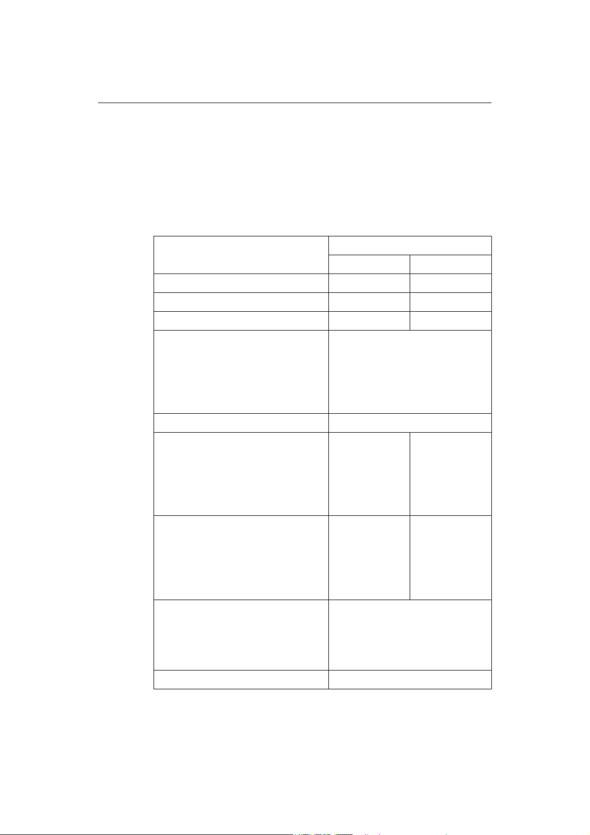
Radar Scanners
CAUTION: Radar Scanners, Cables & Installation
Information on radar scanners, cables and their installation contained in
this handbook supersedes that contained in the Pathfinder Radar
Scanner Handbook, Document No. 81154_8, dated 12th January 2005.
To achieve full radar compatibility with your E-Series Display, your Raymarine radar
scanner may require upgrading. Please check the list below to see if this upgrade is
required.
The scanner serial number can be found on a label attached to the scanner casing:
Scanner type/model Serial Number Compatibility
1220000 and below
2Kw Radome - Pathfinder
2Kw Radome - RD218 All Fully compatible
4Kw Radome - Pathfinder
4Kw Radome - RD424 All Fully compatible
4Kw Open Array
10Kw Open Array 0430000 and below
1220001 - 0530157
0530158 and above
1220000 and below
1222001 - 0530246
0530247 and above
1030000 and below
1030001 - 1230143
1230144 and above
0430001 and above
Not compatible
Upgrade required
Fully compatible
Not compatible
Upgrade required
Fully compatible
Not compatible
Upgrade required
Fully compatible
Not compatible
Fully compatible
The Open Array system will also require a split pedestal cable.
If your radar scanner requires upgrading, please contact your local Raymarine dealer
for full information.
Digital Sounder Module
Important:
In order for your Digital Sounder Module (DSM) to be compatible with your E-Series
display, you will need a DSM300 (Part no. E63049).
Engines
For up-to-date information relating to compatible engines together with installation
information, please refer to our website.

12 E-Series Installation Manual
Media storage cards
Navionics Chart cards
To use your E-Series Display as a navigation aid, charts with detailed information for
the area you wish to navigate are required. The charts are available on Navionics
Chart cards.
A chart card provides an appropriate level of detail and scale for a given geographic
area. Up to 6 Gold or 2 Platinum chart cards can be used in an E-Series Networked
system.
To obtain suitable Navionics Chart Cards, contact your local dealer or visit the
Navionics web sites: www.navionics.com or www.navionics.it.
Alternatively, in North America call Navionics toll-free on 1-800-848-5896.
Outside of North America, contact your local dealer or call Navionics SpA on tel:
(+39) 0584 961696 or fax: (+39) 0584 961309.
CompactFlash cards
®
It is possible to archive or transfer information to and from your E-Series display and
other compatible instruments using CompactFlash cards. To achieve the best results it
is recommended that SAN DISK
2.3 Functionality
For full functionality some applications require a dedicated transducer to provide
specific data. The table on
and the major functions of your E-Series Display.
In particular, position, heading and speed data are required for the following functions:
• Orientation - requires heading data derived from a suitable compass, for the
radar to operate in North Up or Course Up mode and the chart to operate in Course
Up and Head Up modes.
• Man Overboard (MOB) - requires heading and speed data. Alternatively, use
speed over ground (SOG) and course over ground (COG) derived from the same
source as position data (GPS).
• Mini Automatic Radar Plotting Aid (MARPA) and radar/chart over-
lay functions - requires accurate heading data. MARPA functionality is provided
if SOG and COG are also available. Increased accuracy will be obtained by using
fast heading data from a suitable compass, Smart heading sensor or compatible
Raymarine autopilot.
®
CF memory cards are used.
page 13
summarizes the data required by each application
 Loading...