


Distributed by
Any reference to Raytheon or RTN in this manual should be interpreted as Raymarine. The names Raytheon and RTN are owned by the
Raytheon Company.
ST40 Wind
Instrument
Owner’s
Handbook
Document number: 81160_3
Date: 1st May 2001
Copyright © Raymarine Limited 2001
Preface |
i |
Important information
WARNING
Although your ST40 instrument is designed to give accurate and reliable performance, it should serve only as an aid to navigation and should never lead to the erosion of good seamanship. Always maintain a permanent watch and be aware of situations as they develop.
EMC conformance
All Raymarine equipment and accessories are designed to the best industry standards for use in the leisure marine environment.
The design and manufacture of Raymarine equipment and accessories conform to the appropriate Electromagnetic Compatibility (EMC) standards, but correct installation is required to ensure that performance is not compromised.
Handbook information
To the best of our knowledge, the information in this handbook was correct when it went to press. However, the Raymarine policy of continuous product improvement may change product specifications without notice. Consequently, unavoidable differences may occur between the product and the handbook from time to time, for which Raymarine cannot accept liability.
ii |
ST40 Wind Instrument Owner’s Handbook |

Preface |
iii |
Contents |
|
Important information .......................................................... |
i |
WARNING ......................................................................... |
i |
EMC conformance ............................................................. |
i |
Handbook information ....................................................... |
i |
Preface ..................................................................................... |
v |
Parts supplied ................................................................... |
vi |
Chapter 1: Operation ............................................................. |
1 |
1.1 Introduction ................................................................. |
1 |
1.2 Operating procedures .................................................. |
1 |
Silencing alarms .......................................................... |
1 |
Backlighting and contrast adjustment ......................... |
3 |
1.3 Screen descriptions ..................................................... |
4 |
Apparent and true wind screens .................................. |
4 |
Locked apparent wind screen ...................................... |
4 |
1.4 High wind speed alarm ............................................... |
4 |
Indications ................................................................... |
5 |
True wind ............................................................... |
5 |
Apparent wind ....................................................... |
5 |
Enabling/disabling alarm ............................................. |
5 |
Chapter 2: Maintenance and Fault Finding ........................ |
7 |
2.1 Maintenance ................................................................ |
7 |
Servicing and safety .................................................... |
7 |
Instrument .................................................................... |
7 |
Transducer ................................................................... |
8 |
Cabling ........................................................................ |
8 |
2.2 Fault finding ................................................................ |
8 |
Preliminary procedures ............................................... |
8 |
Fixing faults ................................................................. |
8 |
Assistance .................................................................. |
10 |

iv |
ST40 Wind Instrument Owner’s Handbook |
|
|
Chapter 3: Installation ......................................................... |
11 |
|
3.1 Planning your installation ......................................... |
11 |
|
EMC installation guidelines ...................................... |
11 |
|
Suppression Ferrites ........................................... |
12 |
|
Connections to Other Equipment ......................... |
12 |
|
Tools required ........................................................... |
12 |
|
Site requirements ....................................................... |
13 |
|
Rotavecta wind transducer ................................... |
13 |
|
Instrument ............................................................ |
13 |
|
3.2 Procedures................................................................. |
14 |
|
Fitting Rotavecta transducer ...................................... |
14 |
|
Running transducer cable .................................... |
15 |
|
Connections to the instrument ................................... |
16 |
|
Stand-alone connections ...................................... |
17 |
|
SeaTalk connections ............................................ |
18 |
|
Fitting the instrument................................................. |
18 |
|
Desktop Mounting Bracket .................................. |
20 |
|
3.3 Calibration requirement ............................................ |
21 |
|
Chapter 4: Calibration ......................................................... |
23 |
|
4.1 Introduction ............................................................... |
23 |
|
EMC conformance .................................................... |
23 |
|
4.2 User calibration ......................................................... |
23 |
|
4.4 Dealer calibration ...................................................... |
25 |
|
Instrument Specification .................................................... |
27 |
|
Glossary ................................................................................. |
29 |
|
Index ...................................................................................... |
31 |

Preface |
v |
Preface
Thank you for purchasing a Raymarine product. We are sure your
ST40 instrument will give you many years of trouble-free operation.
This instrument is designed to provide reliable performance, even under the most demanding conditions.
-2 D4808
vi |
ST40 Wind Instrument Owner’s Handbook |
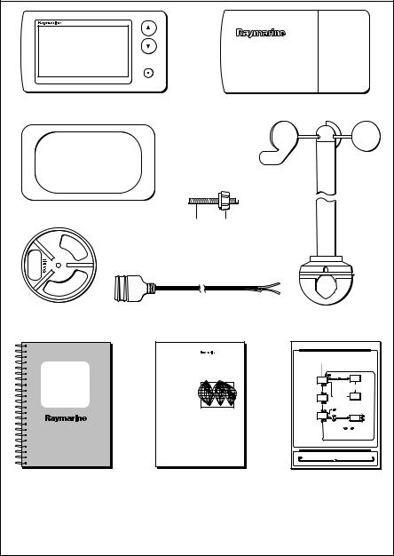
Parts supplied
ST40 |
WIND |
ST40 Wind instrument
Gasket
Clamping bracket
ST40
Wind
Instrument
Owner's
Handbook
Instrument Cover
Fixing Thumb
stud nut
|
|
|
Rotavecta wind transducer |
|
|
|
|
1 m (3 ft) power cable |
|||
Worldwide
Distributors
ST40 Wind Instrument - quick reference guide
|
|
Normal operation |
|
|
SWITCH ON |
|
|
|
|
|
Locked |
|
Apparent |
|
apparent |
|
wind |
|
wind |
|
|
|
Course computer |
|
|
|
sets vane lock |
Available only if boat |
|
Course computer |
Auto locked |
speed information is |
True |
sets vane lock |
wind |
present on SeaTalk |
wind |
|
|
|
Alarm on/off |
|
|
Only available on master |
3 seconds |
|
|
High |
+ |
||
instruments. Times out to the |
|||
previous permanent screen |
wind speed |
Set |
|
after 5 seconds. |
alarm |
alarm |
|
|
|
level |
|
|
Momentary |
- |
|
|
With Set alarm level screen displayed, |
||
|
|
press the |
|
|
and |
keys simultaneously |
|
|
to save the alarm level and return to |
||
|
normal operation. |
||
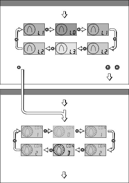
Adjusting display backlighting/contrast
To enter adjust mode, press  for 1 second to adjust BACKLIGHTING and a further 1 second to adjust CONTRAST
OFF 
 LEVEL 1
 LEVEL 2
  LEVEL 3
 LEVEL 2
  LEVEL 1
To exit adjust mode press or
or or wait for 5 second timeout
Owner’s Handbook. |
Worldwide Service Centre |
Quick Reference Guide |
Warranty document and fitting |
Handbook. |
|
templates included in Handbook |
|
|
Note:
The items shown here are supplied for an ST40 Wind system. If an instrument is purchased separately, a transducer is not included. If any item is not present, contact your Raymarine Dealer.
D4752-3
Chapter 1: Operation |
1 |
Chapter 1: Operation
1.1 Introduction
Your ST40 Wind instrument:
•Provides apparent wind speed and direction information. Wind speed units can be either knots (KTS) or metres per second (M/S), as set during User calibration (see Chapter 4, Calibration).
•Provides true wind speed and direction information, if boat speed information is available on SeaTalk.
•Enables a locked apparent wind angle to be defined either manually, or automatically by a course computer. In this mode, the instrument shows the deviations from the locked wind angle and the direction to steer to achieve the locked wind angle.
CAUTION
Your instrument is calibrated to factory (default) settings when first supplied and must therefore be calibrated before use, to ensure optimum performance on your vessel. Do NOT use the instrument until the calibration procedures have been satisfactorily completed, using the procedures in Chapter 4, Calibration.
Coloured bezel and Desktop Mounting Bracket options are available for your ST40 instrument. Contact your Raymarine dealer for further information.
1.2 Operating procedures
Operating information is presented in flow chart form. The flow charts show the various operating screens and key presses necessary to carry out the various instrument functions. Key presses are momentary unless otherwise stated.
Silencing alarms
To silence an alarm (see the Alarms section, later in this chapter), momentarily press any one of the instrument keys.

2 |
ST40 Wind Instrument Owner’s Handbook |
NORMAL OPERATION
Switch on
Increase locked
wind angle
Locked apparent
Apparent  wind wind


STEER
ST40 |
WIND |
ST40
True wind
CAL
WIND |
Decrease locked |
|
|
|
|
Course computer |
wind angle |
|||
|
|
|
enters vane lock |
|
|
||
Course computer |
|
|
|
||||
|
|
|
|
|
|
|
|
enters vane lock |
Auto locked |
|
|
|
|
||
|
apparent |
|
|
|
|
||
|
|
|
|
||||
|
wind |
|
|
||||
|
|
|
|
|
|
|
|
ST40 |
WIND |
If boat speed information |
|
(from SeaTalk) is not present, |
|
true wind information is not |
|
available and this screen is displayed |
|
ST40 |
WIND |
High wind |
|
Alarm |
|
|
|
speed alarm |
|
on/off |
Set high wind |
|
|
|
|
|
speed alarm |
Increase |
|
|
|
3 seconds |
threshold |
|
|
|
|
|
|
|
|
ST40 |
WIND |
+ |
|
|
|
|
|
Momentary |
ST40 |
WIND |
|
|
|
|
With Set high wind speed alarm |
Decrease |
|
|
|
|
threshold screen displayed, press the |
|
|
|
|
|
and |
keys simultaneously |
|
|
|
|
to save the alarm level and return to |
|
|
|
|
|
normal operation. |
|
|
Note: The High wind speed alarm screen is available only on master instruments. It is a temporary screen and will time-out to the previous permanent screen (Apparent wind or True wind) after 5 seconds.
D4753-2
Chapter 1: Operation |
3 |
Backlighting and contrast adjustment
Hold down  for 1 second to enter Adjust Backlight mode
for 2 seconds to move through Adjust Backlight mode and enter Adjust Contrast mode
ADJUST BACKLIGHTING
During normal operation, press for 1 second
The current backlighting level is displayed.
Select the required backlighting level then:
to adjust contrast, |
to return to normal operation, |
||
press |
for 1 second |
press |
or |
or wait for 5 second timeout
Normal operation
ADJUST CONTRAST
During normal operation, press for 2 seconds
via Adjust Backlighting
The current contrast level is displayed.
Select the required contrast level then press  or
or 
or wait for 5 second timeout
Normal operation
D4856-1
4 |
ST40 Wind Instrument Owner’s Handbook |
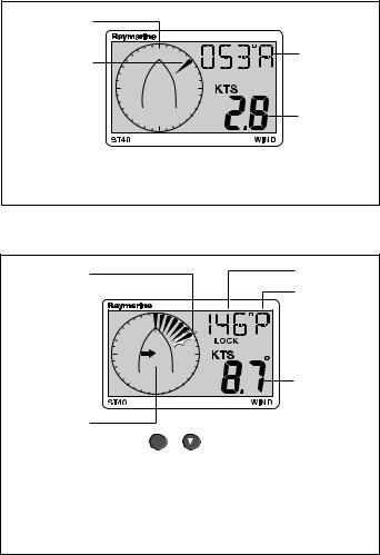
1.3 Screen descriptions
Apparent and true wind screens
Boat heading
Wind direction with respect to boat heading. Either apparent or true.
Wind angle |
Either A (apparent) |
or T (true) |
Wind speed |
Either apparent |
or true, as indicated |
above. |
If apparent wind information is displayed, press  to apply the current wind
bearing as the locked heading
D4792-2
Locked apparent wind screen
Flashing segment indicates the divergence of the apparent wind from the locked wind angle
Direction to steer indicator to achieve locked wind angle
Locked wind angle
P = port,
S = starboard.
Relative direction of the locked wind angle
STEER
Apparent wind speed
Use  or
or
to change locked wind angle, as required.
Press to return to the Apparent wind screen
Note:
In auto lock mode, a similar screen is displayed with an A LOCK annunciator, to indicate that the locked wind angle is controlled by the course computer and cannot be changed manually.
D4793-2
1.4 High wind speed alarm
The high wind speed alarm threshold is set up at the Set high wind speed alarm threshold screen and the alarm sounds if the alarm is switched on and the wind speed exceeds this threshold.

Chapter 1: Operation |
5 |
Indications
ST40 |
WIND |
D4754-2
True wind
If boat speed information is available at the ST40 Wind instrument (from a SeaTalk bus), the alarm is triggered if TRUE wind speed exceeds the threshold.
Apparent wind
If boat speed information is not present, the alarm is triggered if the
APPARENT wind speed exceeds the threshold.
Enabling/disabling alarm
You can enable or disable the high wind speed alarm function (i.e. switch it on or off ) by selecting the Set high wind speed alarm threshold screen (see Normal operation) and holding down the  key for 3 seconds (toggle action).
 Loading...