


 Loading...
DS400X & DS500X
Digital Fishfinders
Owner’s Handbook
Document number: 81234-2
Date: April 2004
ii
DS400X and DS500X Digital Fishfinders |
iii |
Preface
This handbook describes the Raymarine DS400X and DS500X Digital Fishfinders.
Conventions Used
Throughout this handbook, the labelled keys are shown in bold capitals; for example, MENU. The software menu names and options are shown in normal capitals; for example, AUTOMATIC.
Operating procedures, which may consist of a single key-press or a sequence of numbered steps, are indicated by a symbol in the margin.
Technical Accuracy
The technical and graphical information contained in this handbook, to the best of our knowledge, was correct as it went to press. However, the Raymarine policy of continuous improvement and updating may change product specifications without prior notice. As a result, unavoidable differences between the product and handbook may occur from time to time, for which liability cannot be accepted by Raymarine.
Warranty
To register your DS400/500X Digital Fishfinder ownership, please take a few minutes to fill out the warranty registration card found at the end of this handbook. It is very important that you complete the owner information and return the card to the factory in order to receive full warranty benefits.
iv |
DS400X and DS500X Digital Fishfinders |
Important Information
This handbook contains important information on the installation and operation of your new equipment. In order to obtain the best results in operation and performance, please read this handbook thoroughly.
Raymarine’s Product Support representatives, or your authorized dealer, are available to answer any questions you may have.
Intended Use
Raymarine DS400X and DS500X Digital Fishfinders are intended for recreational fishfinding.
EMC Conformance
All Raymarine equipment and accessories are designed to the best industry standards for use in the recreational marine environment.
Their design and manufacture conforms to the appropriate Electromagnetic Compatibility (EMC) standards, but correct installation is required to ensure that performance is not compromised. Although every effort has been taken to ensure that they will perform under all conditions, it is important to understand what factors could affect the operation of the product.
The guidelines given here describe the conditions for optimum EMC performance, but it is recognized that it may not be possible to meet all of these conditions in all situations. To ensure the best possible conditions for EMC performance within the constraints imposed by any location, always ensure the maximum separation possible between different items of electrical equipment.
For optimum EMC performance, it is recommended that wherever possible:
•Raymarine equipment and cables connected to it are:
•At least 3 ft (1 m) from any equipment transmitting or cables carrying radio signals, e.g., VHF radios, cables and antennas.
•More than 7 ft (2 m) from the path of a radar beam. A radar beam can normally be assumed to spread 20 degrees above and below the radiating element.

DS400X and DS500X Digital Fishfinders |
v |
•Raymarine specified cables are used. Cutting and rejoining these cables can compromise EMC performance and must be avoided unless doing so is detailed in the installation manual.
•If a suppression ferrite is attached to a cable, this ferrite should not be removed. If the ferrite needs to be removed during installation it must be reassembled in the same position.
Safety Notices
1.PRODUCT INSTALLATION. This equipment must be installed and operated in accordance with the instructions contained in this handbook. Failure to do so could result in poor product performance, personal injury and/or damage to your boat.
2.HIGH VOLTAGE. The display unit, transducer cable, and transducer
contain high voltages. Adjustments require specialized service procedures and tools only available to qualified service technicians - there are no user serviceable parts or adjustments.
3.NAVIGATION AID. This unit is only an aid to navigation. Its accuracy can be affected by many factors, including equipment failure or defects, environmental conditions, and improper handling or use. It is the user’s responsibility to exercise common prudence and navigational judgments. This fishfinder should not be relied upon as a substitute for such prudence and judgment.
4.ULTRASONIC ENERGY. The transducer transmits high frequency energy while in use. The unit should be turned off when swimmers or divers are in close proximity to the transducer. (There is a lack of scientifically sound standards or guidelines for exposure levels and limits to ultrasound. This notice is precautionary only.)
WARNING:
Do not disconnect the transducer cable without first powering off the display unit. Removal of the transducer cable from the DS400/500X while power is turned on can cause sparks.
Mount unit where it is well ventilated and free from gasoline fumes.
vi |
DS400X and DS500X Digital Fishfinders |
Raymarine Products and Services
Raymarine products are supported by a network of Authorized Service Representatives. Raymarine’s Technical Services representatives or your local dealer will be available to answer any questions you may have. For information on Raymarine products and services, contact either of the following:
United States |
Raymarine, Incorporated |
|
|
22 Cotton Road, Unit D |
|
|
Nashua, New Hampshire |
|
|
03063-4219 USA |
|
|
Telephone:1-603-881-5200 |
|
|
|
1-800-539-5539 |
|
Fax: |
1-603-864-4756 |
Europe |
Raymarine Limited |
|
|
Anchorage Park |
|
|
Portsmouth, Hampshire |
|
|
PO3 5TD England |
|
|
Telephone: +44 (0) 23 9269 3611 |
|
|
Fax: |
+44 (0) 23 9269 4642 |
Or, you may contact us on the World Wide Web at:
www.raymarine.com
© Raymarine Limited 2004

|
|
vii |
Contents |
|
|
Preface ................................................................................................................... |
|
iii |
Conventions Used ................................................................................... |
iii |
|
Technical Accuracy ................................................................................. |
iii |
|
Warranty .................................................................................................. |
iii |
|
Important Information ........................................................................................ |
iv |
|
Intended Use ............................................................................................ |
iv |
|
EMC Conformance ................................................................................. |
iv |
|
Safety Notices ........................................................................................... |
v |
|
Raymarine Products and Services ........................................................... |
vi |
|
Chapter 1: Overview ............................................................................................ |
1 |
|
1.1 |
Introduction ...................................................................................... |
1 |
|
Features ......................................................................................... |
2 |
|
General .......................................................................................... |
3 |
|
Transducer .............................................................................. |
3 |
Chapter 2: Installation ......................................................................................... |
5 |
|
2.1 |
Introduction ...................................................................................... |
5 |
2.2 |
Unpacking and Inspecting the Components ..................................... |
5 |
2.3 |
Selecting the Equipment Location ................................................... |
6 |
|
Mounting Location ....................................................................... |
6 |
2.4 |
Cable Runs ....................................................................................... |
7 |
2.5 |
Mounting the Fishfinder ................................................................. |
10 |
|
Bracket Mounting ....................................................................... |
10 |
|
Console Mounting (optional) ..................................................... |
10 |
2.6 |
System Connections ....................................................................... |
12 |
|
DC Power and NMEA Connection ............................................. |
12 |
|
Transducer Connection ............................................................... |
14 |
Chapter 3: Getting Started ................................................................................ |
15 |
|
3.1 |
Introduction .................................................................................... |
15 |
3.2 |
Powering on the Fishfinder ............................................................ |
15 |
3.3 |
Simulator Mode .............................................................................. |
15 |
3.4 |
LCD Display .................................................................................. |
16 |
3.5 |
Interpreting the Sounder Image ...................................................... |
17 |
|
Target Indications ....................................................................... |
18 |
3.6 |
Keypad Operation .......................................................................... |
19 |
3.7 |
Using the Variable Range Marker (VRM) ..................................... |
20 |
3.8 |
Selecting the Display Page ............................................................. |
21 |
3.9 |
Menu Operation ............................................................................. |
23 |
|
Menu Structure ........................................................................... |
23 |

viii |
DS400 and DS500 Digital Fishfinders |
|
Chapter 4: Main Menu ....................................................................................... |
25 |
|
4.1 |
Introduction .................................................................................... |
25 |
|
Selecting MENU Items ............................................................... |
25 |
4.2 |
Fishfinder Operation Controls ........................................................ |
29 |
|
Scroll Speed ................................................................................ |
30 |
|
Range .......................................................................................... |
30 |
|
Frequency ................................................................................... |
32 |
|
A-Scope ...................................................................................... |
33 |
|
GAIN MODE... .......................................................................... |
34 |
|
GAIN .................................................................................... |
35 |
|
Color Gain ............................................................................. |
35 |
|
Time Variable Gain (TVG) ................................................... |
36 |
|
Sounder Interference Rejection (Int. Rej.) ............................ |
36 |
|
Second Echo Rejection ......................................................... |
37 |
|
Power .................................................................................... |
37 |
|
Max. Ping Rate ...................................................................... |
37 |
|
ZOOM... ..................................................................................... |
37 |
|
View ...................................................................................... |
38 |
|
Zoom x2, x3, x4 Magnification ............................................. |
39 |
|
Mode ..................................................................................... |
39 |
|
TRIP RESET... ............................................................................ |
39 |
|
DISPLAY SET UP... ................................................................... |
39 |
|
SOUNDER SET UP... ................................................................. |
39 |
Chapter 5: Display Set Up .................................................................................. |
41 |
|
5.1 |
Introduction .................................................................................... |
41 |
|
Brightness ................................................................................... |
44 |
|
Target Depth ID .......................................................................... |
44 |
|
Depth Digit Size .......................................................................... |
45 |
|
Transparent Menu ....................................................................... |
45 |
|
PALETTE... ................................................................................ |
46 |
|
Selection ............................................................................... |
46 |
|
Background Color ................................................................. |
47 |
|
DATA ITEMS... .......................................................................... |
47 |
|
NAV. SET UP... (Navigation Data) ............................................. |
48 |
Chapter 6: Sounder Set Up ................................................................................ |
51 |
|
6.1 |
Introduction .................................................................................... |
51 |
|
ALARMS... ................................................................................ |
55 |
|
Target Depth ID ..................................................................... |
55 |
|
Fish Alarm ............................................................................ |
56 |
|
Shallow Alarm ...................................................................... |
56 |
|
Shallow Range ...................................................................... |
56 |
|
Deep Alarm ........................................................................... |
57 |

|
|
ix |
|
Deep Range ........................................................................... |
57 |
|
Temp. Alarm ......................................................................... |
57 |
|
Temp. Rng. High ................................................................... |
58 |
|
Temp. Rng. Low ................................................................... |
58 |
|
ALARM CLOCK... .............................................................. |
58 |
|
UNITS... ..................................................................................... |
59 |
|
Depth Units ........................................................................... |
59 |
|
Temp. Units ........................................................................... |
59 |
|
Speed Units ........................................................................... |
59 |
|
Distance Units ....................................................................... |
59 |
|
Bearing Mode ....................................................................... |
60 |
|
Date Format .......................................................................... |
60 |
|
Time Format .......................................................................... |
60 |
|
NMEA-OUT SET UP... .............................................................. |
60 |
|
Language .................................................................................... |
61 |
|
Key Beep .................................................................................... |
61 |
|
Key Help ..................................................................................... |
61 |
|
Depth Offset ................................................................................ |
62 |
|
Speed Calibrate ........................................................................... |
62 |
|
Temp Calibrate ............................................................................ |
62 |
|
Sounder Simulator ...................................................................... |
62 |
|
SW Version and Serial Number (read only) ................................ |
62 |
Chapter 7: Maintenance and Problem Solving ............................................... |
63 |
|
7.1 |
Maintenance ................................................................................... |
63 |
|
Routine Checks ........................................................................... |
63 |
|
Cleaning Instructions .................................................................. |
63 |
|
Cleaning the Unit .................................................................. |
63 |
|
Cleaning the Transducer ....................................................... |
63 |
|
Cleaning the Hull .................................................................. |
64 |
|
EMC Servicing and Safety Guidelines ....................................... |
64 |
7.2 |
Problem Solving ............................................................................. |
65 |
|
Common Problems and Their Solutions ..................................... |
65 |
7.3 How to Contact Raymarine ............................................................ |
66 |
|
|
On the Internet ............................................................................ |
66 |
|
Customer Support ................................................................. |
66 |
|
In the US ..................................................................................... |
66 |
|
Accessories and Parts ............................................................ |
66 |
|
Technical Support ................................................................. |
67 |
|
Product Repair and Service ................................................... |
67 |
|
In Europe ..................................................................................... |
68 |
|
Technical Support ................................................................. |
68 |
|
Accessories and Parts ............................................................ |
68 |

x |
DS400 and DS500 Digital Fishfinders |
Worldwide Support |
..................................................................... 68 |
Appendix A: Specifications ................................................................................ |
69 |
Index ...................................................................................................................... |
71 |
Chapter 1: Overview |
1 |
Chapter 1: Overview
1.1 Introduction
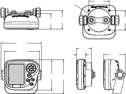
This handbook describes the DS400X and DS500X Digital Fishfinders. The DS400/500X feature state-of-the-art High Definition Fish Imaging (HDFI) technology. Constantly adjusting transmitter and receiver parameters throughout the water column, the DS400/500X intelligently analyzes fish and bottom echoes and automatically produces a crystal clear echo sounder display.
D6437-2
Figure 1-1: DS400X Digital Fishfinder
D6445-2
Figure 1-2: DS500X Digital Fishfinder

2 |
DS400X and DS500X Digital Fishfinders |
|
|
The DS400/500X employs a very high transmission repetition or “ping” rate which, along with the digital adaptive high sample rate receiver, ensures that fish and bottom structure are presented in superb detail and optimal color allocation. The DS400/500X digital bandwidth adaptation adjusts the receiver band width dynamically from very wide to very narrow, as required by the actual water conditions. This provides superior fish and bottom detection in all water conditions.
Features
•DS500X: 5" Transmissive High Brightness TFT Color LCD DS400X: 3.5" Transflective Daylight Viewable TFT Color LCD
•¼ VGA 76,800 Pixel Display Resolution
•Patented Digital HDFI Technology
•Hands-Off Adaptive Auto Adjustments
•Dual Frequency 200/50 kHz 500W RMS
•Depth/Temp/Speed transducer included with some models, which can measure water depth, water temperature and speed
•Speedometer-style digital data screen overlay
•NMEA 0183 compliant
•Easy Bracket or Flush mounting
•Waterproof to IPX7
1 - D6451
Fishfinder


 Transducer
Figure 1-3: Basic Fishfinder System using the DS400/500X
Chapter 1: Overview |
3 |
General
The DS400/500X system, illustrated below, is comprised of the digital fishfinder, transducer and associated cables.
The DS400/500X is waterproof to IPX7 and can be installed either above or below deck.
The unit includes connections to:
•Power/NMEA
•the transducer
Transducer
The DS400/500X requires a transducer for measuring water depth, water temperature, distance traveled, and speed. A transducer is included with some fishfinder models. It is important to position your transducer correctly. Details on your transducer, including location and installation instructions, are included in the transducer box.
4 |
DS400X and DS500X Digital Fishfinders |
|
|

Chapter 2: Installation |
5 |
Chapter 2: Installation
2.1 Introduction
This chapter provides installation instructions for your DS400/500X.
Note: If you wish to practice using the unit before installation, connect the power cable and use the simulator mode as described in Chapter 3. For power, connect a 12VDC power supply, attaching the red wire to positive and the black wire to negative. See Section 3.3 for details.
2.2 Unpacking and Inspecting the Components
Unpack your system carefully, to prevent damage to the equipment. Save the carton and packing, in case you need to return a unit for service.
Check that you have all the correct system components. These depend on your system package, as follows:
:
Table 2-1: Supplied Parts
Item |
Part No. |
|
|
One of the following units: |
|
DS400X Digital Fishfinder without Transducer, US version |
E63061 |
DS400X Digital Fishfinder without Transducer, CE version |
E63062 |
DS500X Digital Fishfinder without Transducer, US version |
E63063 |
DS500X Digital Fishfinder without Transducer, CE version |
E63064 |
|
|
Sun Cover, DS400X |
R69070 |
Sun Cover, DS500X |
R69071 |
|
|
Mounting Bracket, DS400X |
R69072 |
Mounting Bracket, DS500X |
R69075 |
|
|
Mounting Bracket Knobs, DS400X, DS500X |
R69073 |
|
|
Power/NMEA cable |
R69074 |
|
|
Handbook, DS400/500X |
81234 |
|
|
Mounting hardware |
N/A |
|
|

6 |
DS400X and DS500X Digital Fishfinders |
The following accessories are available for your A Series Fishfinder:
Table 2-2: Optional Accessories
Item |
Part No. |
|
|
Flush Mount Kit, DS400X |
E66067 |
Flush Mount Kit, DS500X |
E66068 |
|
|
Transducers are supplied with some models and optional with others. The following transducer options are available:
:
Table 2-3: Transducer Parts
Item |
Part No. |
|
|
Transducer Adapter Cable for L365/L470 Style Transducers |
E66070 |
|
|
Transducer Adapter Cable for hsb2/DSM250 Style Transducers |
E66066 |
|
|
Transom Mount Transducer for DS400X/DS500X/DS600X (P58)1 |
E66062 |
|
|
Bronze Thru-hull Transducer for DS400X/DS500X/DS600X (B744V)1 E66061
1supplied with some models
2.3 Selecting the Equipment Location
Mounting Location
The DS400/500X is waterproof to IPX7 is and designed to be mounted either above or below deck. The unit should be protected from physical damage and excessive vibration.
CAUTION:
Mount the DS400/500X in a protected area away from prolonged exposure to rain, salt spray, and direct sunlight, but well ventilated.
When planning the installation, the following should be considered to ensure reliable and trouble free operation:
•Access: There must be sufficient space below the unit to enable cable connections to the panel connectors, avoiding tight bends in the cable.
•Interference: The selected location should be far enough away from devices that may cause interference, such as motors, generators, and radio transmitter/receivers. (See the EMC guidelines in the Preface.)
•Magnetic compass: Mount the unit at least 3 ft (1m) away from a magnetic compass.

Chapter 2: Installation |
7 |
•Cable runs: The unit must be located near a DC power source. The power cable supplied is 5 ft (1.5 m), but a longer cable can be used if desired. Refer to Section 2.4.
The maximum length of cable between the fishfinder and the transducer unit should not normally exceed 25 ft (8 m).
•Environment: Good ventilation is required to prevent overheating.
WARNING:
Removing the transducer cable from the DS400/500X while power is turned on can cause sparks. As with any electronic device, be sure the fishfinder is mounted where it is well ventilated and free from gasoline fumes.
2.4 Cable Runs
Consider the following before installing the system cables:
•You will need to attach the power and transducer cables to the rear of the unit.
•All cables should be adequately secured, protected from physical damage and exposure to heat.
•Avoid running cables through bilges or doorways, or close to moving or hot objects.
•Avoid sharp bends.
•Where a cable passes through an exposed bulkhead or deckhead, use a watertight feed-through.
•Secure cables in place using tie-wraps or lacing twine. Coil any extra cable and tie it out of the way.
You will need to run the following cables:
•Power/NMEA cable, supplied with the unit. This 5 ft (1.5 m) cable has a connector plug at one end for connecting to the fishfinder, and 3 wires at the other end for connecting the power supply. The power cable may be extended by up to 60 ft (20 m) using a wire gauge of AWG 12 or greater. The DS400/500X is intended for use on the boat’s DC power systems rated from 10-18 Volts DC (13.8V nominal).
•Transducer cable, supplied with the transducer. This 25 ft (8 m) cable has a connector plug at one end for the display unit.
8 |
DS400X and DS500X Digital Fishfinders |
Cutting the transducer cable will severely reduce sonar performance:
•Do not cut the transducer cable or remove the connector.
•Do not shorten or splice the cable.
If the transducer cable is cut, it must be replaced—it cannot be repaired. Cutting the cable will also void the warranty.
2.99 in
(76 mm)
 3.46 in
(88 mm)
2.28 in |
2.70 in |
2.83 i |
(57.9 mm) |
(68.6 mm) |
(72 m |
5.88 in
(149.4 mm)
|
2.28 in |
5.12 in |
(57.9 mm) |
(130 mm) |
1.3 in |
3.17 in |
|
(80.5 mm) |
|
|
(33.2 mm) |
|
|
|
4.45 in |
5.0 in |
(113 mm) |
(127 mm) |
D6440-2
Figure 2-1: DS400X Unit Dimensions

Chapter 2: Installation |
9 |
5.88 in
(149.4 mm)
6.37 in
(161.8 mm)
Figure 2-2:
3.46 in
(88 mm)
3.08 in
(78.3 mm)
2.66 in
(67.6 mm)
2.66 in
(67.6 mm)
1.68 in
(42.7 mm)
6.22 in
(158 mm)
5.9 in
(150 mm)
2.99 in
(76 mm)
2.83
(72 m
3.81 in
(96.7 mm)
D6448-2
DS500X Unit Dimensions
10 |
DS400X and DS500X Digital Fishfinders |
2.5 Mounting the Fishfinder
The DS400/500X can be mounted on a dash, chart table, bulkhead or deckhead using the supplied hardware. The unit can also be flush mounted directly into the console.
Bracket Mounting
To mount the DS400/500X on the supplied bracket:
1.Loosen the knobs and remove the mounting bracket from the unit.
2.Mark the locations of the mounting bracket screw holes on the mounting surface.
3.Drill 5/16" (7 mm) holes through the mounting surface at the marked locations.
4.Align the mounting bracket holes with the holes on the mounting surface.
5.Use the screws and nuts supplied to attach the mounting bracket to the mounting surface at the marked locations.
6.Attach the unit to the mounting bracket, adjust the display angle, and tighten the knobs.
Console Mounting (optional)
The fishfinder may also be installed directly into the console. This requires the purchase of an optional Flush Mount kit, Raymarine part number E66067 (for DS400X) or E66068 (for DS500X).
To flush mount the unit directly into the console using the optional kit:
1.Make sure there are no hidden electrical wires or other items behind the location before proceeding. Make sure there is sufficient rear access for mounting and cabling.
2.Check the selected location for the unit. A clear, flat area is required. DS400X: allow at least 5½" (140 mm) wide by 4¾" in (120 mm) high, with at least 3½" (89 mm) of clearance behind the panel.
DS500X: allow at least 6¾" (171 mm) wide by 6¼" (159 mm) high, with at least 3½" (89mm) of clearance behind the panel.
3.Using the template supplied at the end of this handbook, trace out the unit opening and four mounting screw locations.
4.Use a 3-5/8" hole saw to cut the hole through which the circular rear of the unit will pass.
Chapter 2: Installation |
11 |
5.Remove the mounting bracket knobs, bracket and mounting frame from the unit. Make sure that the unit fits in the cut-out area.
6.Drill four 3/16" (5 mm) holes as indicated on the template.
7.Hand tighten the studs into the holes provided at the rear of the unit.
8.Place the gasket on the rear of the fishfinder.
9.Run the Power/NMEA cable and transducer cables through the back of the cutout and connect to the unit. Avoid tight bends in the cables.
10.Slide the unit into the panel cut-out.
11.Hand tighten the nuts to secure the unit to the console.
12.Alternatively, place a spacer over each of the four studs and secure with thumb nuts.
D6631-1 |
Figure 2-3: DS400/500X Flush Mounting Arrangement
12 |
DS400X and DS500X Digital Fishfinders |
2.6 System Connections
The rear of the fishfinder provides the following connection sockets:
•Power/NMEA
•Transducer
D6459-2
Transducer |
Power/NMEA |
Figure 2-4: DS400/500X Connector Panel
DC Power and NMEA Connection
The DS400/500X is intended for use on boat’s DC power systems rated from 10-18 Volts DC (13.8V nominal).
A 5 ft (1.5 m) cable is supplied for connecting the boat’s DC power and NMEA interface to the unit. This Power/NMEA cable can be extended by up to 60 ft (20 m) using a wire gauge of AWG 12 or greater.
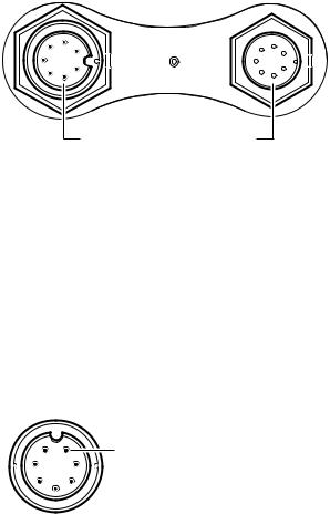
The cable’s molded end attaches to the seven-pin Power/NMEA connector on the unit’s connector panel.
The cable connector (viewed from the outside) is shown in the following drawing.
pin1
D6462-2
Figure 2-5: Power Cable Connector
The exposed wires on the open end of the cable should be connected as follows:
Chapter 2: Installation |
|
13 |
||
|
|
|
|
|
|
Pin No. |
Function |
Color |
|
|
|
|
|
|
1 |
Battery negative – |
Black |
||
|
|
|
|
|
2 |
Battery positive + (10.0VDC to 18.0VDC) |
Red |
||
|
|
|
|
|
3 |
NMEA Input + |
White |
||
|
|
|
|
|
4 |
NMEA Input – |
Green |
||
|
|
|
|
|
5 |
CGND |
Gray |
||
|
|
|
|
|
6 |
NMEA Output + |
Yellow |
||
|
|
|
|
|
7 |
NMEA Output – |
Brown |
||
|
|
|
|
|
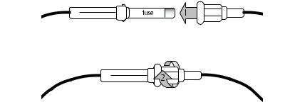
The red wire connects to the feed from the positive (+) battery terminal and the black wire connects to the feed from the negative (–) battery terminal. The shield wire (drain) connects to the boat’s RF ground. If your boat does not have an RF system, you can trim off the drain wire.
A fast blow 2 amp fuse is attached (in-line) to the red (positive) wire.
D6891-1
Figure 2-6: Installing the Fuse
CAUTION:
If the power connections are accidentally reversed the system will not work. Use a multimeter to ensure that the input power leads are connected for correct polarity.

14 |
DS400X and DS500X Digital Fishfinders |
Transducer Connection
A 25ft (8m) cable is supplied with the transducer. The transducer cable connector has a nut that has been removed to aid installation. To enable you to complete the installation without cutting the cable, ensure that any holes you drill are large enough to accept the connector, with the nut removed (approximately 13/16" or 21 mm).
Before attaching the transducer cable, you will need to attach the connector nut, which is included in the transducer packaging.
The transducer cable is attached to the 7 pin male TRANSDUCER connector on the connector panel of the DS400/500X. (See Figure 2-3 .)
CAUTION:
•Do not pull on the cable. This can damage the transducer wires.
•Do not cut the transducer cable or remove the connector.
•Do not try to shorten or splice the cable. Cutting the transducer cable will severely reduce sonar performance.
•If the cable is cut, it must be replaced—it cannot be repaired. Cutting the cable will also void the warranty.
WARNING:
Removing the transducer cable from the rear of the DS400/500X while the fishfinder is powered on can cause sparks. Only remove the transducer cable after power has been removed from the DS400/500X.
If the transducer cable is accidentally removed while the DS400/500X is powered on, remove power from the fishfinder, replace the transducer cable, and then restore power. As a safety feature, the DS400/500X only recognizes that the transducer is connected at power-up.

Chapter 3: Getting Started |
15 |
Chapter 3: Getting Started
3.1 Introduction
This chapter provides basic instructions to get you started using the DS400/ 500X Digital Fishfinder. It describes Simulator mode and can help you to become familiar with the basic functions of the fishfinder’s operation controls. More detailed information on using the menu items and display controls is provided in Chapter 4 and Chapter 5, respectively.
3.2 Powering on the Fishfinder
Connect the power cord to boat’s power source and plug into the power port PWR on the connector panel. Press the PWR button on the DS400/500X.
Details on setting up your DS400/500X and display are given in Chapter 6.
3.3 Simulator Mode
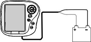
If you have not fully installed the fishfinder, you can still operate in Simulator mode by connecting the fishfinder to a 12VDC power supply.
Figure 3-1 demonstrates how to setup the DS400/500X for Simulator mode. Attach the red wire from the power lead to positive (+) and the black wire to negative (–).
When you power up the DS400/500X without connecting the transducer, the unit enters Demo mode. This provides a preprogrammed demonstration highlighting the fishfinder’s main features. This function enables you to practice operating the fishfinder without data from the transducer, using simulated data.
If the transducer is connected, you can enter Simulator Mode by following instructions outlined on page 62.
16 |
DS400X and DS500X Digital Fishfinders |
Fishfinder
Red |
Black |
DC Volts
D6638-1
Figure 3-1: Demo/Simulator Mode Setup
3.4 LCD Display
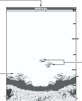
When you first switch on the fishfinder, the scrolling bottom graph, or Fishfinder Page, is displayed. This is a graphical representation of the echoes seen by the DS400/500X. As time passes, this display scrolls from right to left and becomes a record of the echoes seen. A typical display is shown in
Figure 3-2 .
The images at the right hand side of the display are the most recent echoes. Some echoes indicate fish, and others show the bottom. It can also indicate bottom structures, such as a reef or shipwreck. The upper and lower depth range limits are shown.
You can customize the sounder by choosing what is displayed and how it is displayed (including language and units). For example, you can set whether the bottom graph display scrolls and you can select the range to adjust the depth displayed.
You can view the cursor position and a variety of data (such as speed and depth) from the transducer and other equipment in user-selectable data boxes. These data boxes can be moved around the screen and they can be switched on or off.
Chapter 5 includes details on adjusting the display, other set up options are described in Chapter 6.
Chapter 3: Getting Started |
17 |
Frequency


 Bottom of
transducer
20 |
|
Depth markers |
|
|
|
|
|
34 |
36 |
|
|
|
|
|
|
|
|
|
|
|
|
|
|
Target images |
|
|
|
|
|
42 |
43 |
40 |
|
|
|
|
Target depth |
43 |
43 |
|
|
|
|
||||
|
|
44 |
44 |
|
|
|
|
Bottom |
||
|
|
|
|
47 |
47 |
|
|
|
|
|
|
|
|
|
|
|
|
|
|
||
Bottom depth |
|
|
43.9ft |
|
60 |
|
|
|
Range |
|
|
|
|
|
|
|
|||||
|
|
|
|
|
|
|
||||
|
|
|
|
|
|
D6637-2 |
|
|
|
|
Figure 3-2: Typical Fishfinder Display Screen
3.5 Interpreting the Sounder Image
The DS400/500X uses sound waves to find fish and show bottom structure. The transducer sends sound waves into the water; these sound waves strike fish, the bottom, or other objects in the water and return as echoes. The DS400/500X interprets these echoes to present an image of the fish and bottom.
The strength of echoes is indicated by different colors. You can use this information to determine the size of fish and the bottom structure. Other objects in the water, such as debris and air bubbles, also return echoes; these echoes are generally weaker than the fish or bottom echoes and produce background noise or clutter on the display. The digital sounder provides controls to reduce the background noise and to adjust the way in which echoes of different strengths are displayed.
18 |
DS400X and DS500X Digital Fishfinders |
Target Indications
When the sounder detects a target echo such as a fish, it displays a representative image on the LCD. The shape and size of this image is influenced by a combination of factors:
Boat speed
The shape of the target changes along with your speed. Slower speeds return flatter, more horizontal images. As your boat’s speed increases, the image will tend to thicken and arch slightly.
The depth of the target
The closer the target to the surface the larger the image on screen.
To display the depth of individual targets, switch on the TARGET DEPTH ID from the menu, as described on page 44.
The size of the target
The larger the target, the larger the return on the fishfinder display. The size of a fish target is however dependent upon the size of the fish’s swim bladder rather than its overall size. This swim bladder will vary in size between different breeds of fish.
The frequency of the transducer
The same target will appear differently when the transducer frequency is changed. Generally, the lower the frequency the broader the image.
Loading...