


 Loading...
A65
GPS Chartplotter
Owner’s Handbook
Document number: 81248-2
Date: March 2006
Trademarks and registered trademarks
Raymarine is a registered trademark of Raymarine plc. Navionics is a registered trademark of Navionics SpA. SanDisk is a registered trademark of SanDisk Corporation.
Microsoft and Windows are registered trademarks of Microsoft Corporation. Google is a trademark of Google, Inc.
All other product names are trademarks or registered trademarks of their respective owners.
Contents of this handbook © Raymarine 2006

|
|
3 |
Contents |
|
|
Important Information ....................................................................................... |
7 |
|
Intended Use .................................................................................................. |
7 |
|
Safety Notices ............................................................................................... |
7 |
|
Electronic Chart Cards .................................................................................... |
8 |
|
Technical Accuracy .......................................................................................... |
8 |
|
Chapter 1: Using the Display ............................................................................. |
9 |
|
1.1 |
System Overview ................................................................................. |
9 |
|
Powering the Display ON/OFF .............................................................. |
10 |
|
Adjusting the Display Lighting ............................................................. |
10 |
1.2 |
The Controls ....................................................................................... |
11 |
1.3 |
Selecting How the Applications are Displayed ..................................... |
12 |
|
Selecting a Page ................................................................................. |
12 |
|
Chart Page ......................................................................................... |
12 |
|
Fishfinder Page ..................................................................................... |
14 |
|
Data Pages ........................................................................................... |
15 |
1.4 |
The Simulator ..................................................................................... |
18 |
Chapter 2: General Operation and System Setup .......................................... |
21 |
|
2.1 |
Introduction ......................................................................................... |
21 |
2.2 |
Controls ............................................................................................... |
21 |
|
Keys ...................................................................................................... |
21 |
|
Soft Keys .............................................................................................. |
23 |
|
Cursor ................................................................................................ |
23 |
2.3 |
Status Bar ............................................................................................. |
24 |
2.4 |
Displaying Control Information on the Screen ...................................... |
25 |
|
Soft Keys .............................................................................................. |
25 |
|
Dialog Boxes ........................................................................................ |
25 |
|
Pop-up Messages ................................................................................. |
25 |
|
Database Lists ...................................................................................... |
26 |
2.5 |
Setting up the Display .......................................................................... |
26 |
2.6 |
Chart Setup Menu .............................................................................. |
27 |
|
Chart Setup ........................................................................................ |
29 |
2.7 |
Fishfinder Setup ............................................................................... |
32 |
2.8 |
System Setup ................................................................................... |
32 |
2.9 |
Alarm Setup Menu ........................................................................... |
35 |
|
Navigation Alarms Setup .................................................................. |
35 |
|
Fishfinder Alarms Setup ....................................................................... |
36 |
2.10 |
GPS Status ......................................................................................... |
36 |
2.11 |
Display Setup ..................................................................................... |
38 |
|
Brightness .......................................................................................... |
38 |
|
Data Items ......................................................................................... |
38 |
4 |
|
A65 GPS Chartplotter |
|
|
|
|
Key Beep ............................................................................................. |
39 |
|
Digital Compass ................................................................................. |
39 |
2.12 |
System Diagnostics ............................................................................ |
39 |
2.13 |
User Card Menu ................................................................................. |
40 |
|
User Card Manager... ............................................................................ |
40 |
|
Save Image to User Card... .................................................................... |
40 |
|
Remove User Card... ............................................................................. |
41 |
2.14 |
Inserting and Removing the CompactFlash Card .................................. |
41 |
|
Inserting a CF Card ............................................................................. |
42 |
|
Removing a CF Card ............................................................................. |
43 |
2.15 |
Saving and Retrieving Data ................................................................ |
43 |
|
Save Information to a CompactFlash Card ............................................ |
44 |
|
Retrieve Information from a CompactFlash Card .................................. |
44 |
|
Sending and Receiving Information using NMEA ................................. |
44 |
Chapter 3: Working with Waypoints .............................................................. |
45 |
|
3.1 |
Introduction .......................................................................................... |
45 |
|
Man Overboard (MOB) ....................................................................... |
46 |
3.2 |
Placing a Waypoint ............................................................................... |
47 |
3.3 |
Navigating to a Waypoint (GOTO) ...................................................... |
49 |
|
... using the cursor ................................................................................ |
49 |
|
... via the WPTS/MOB key ..................................................................... |
49 |
|
Navigating to a Waypoint Sent by NMEA ........................................... |
50 |
3.4 |
Viewing Waypoint Information .......................................................... |
51 |
3.5 |
Editing a Waypoint ............................................................................. |
53 |
|
Change the Default Symbol ............................................................... |
53 |
|
Changing the Waypoint Symbol ......................................................... |
53 |
|
Changing the Waypoint Details .......................................................... |
56 |
|
Moving a Waypoint .............................................................................. |
58 |
|
Erasing a Waypoint ............................................................................. |
59 |
3.6 |
Controlling How Waypoints are Displayed ........................................... |
60 |
Chapter 4: Using the Chartplotter .................................................................... |
61 |
|
4.1 |
Introduction .......................................................................................... |
61 |
|
Using your Chartplotter Safely .............................................................. |
61 |
4.2 |
Man Overboard (MOB) ....................................................................... |
62 |
4.3 |
What is Displayed ................................................................................. |
63 |
|
Electronic Charts .................................................................................. |
63 |
|
Chart Orientation and Relative Motion ................................................. |
63 |
4.4 |
The Chartplotter Display ....................................................................... |
64 |
|
Find Ship ............................................................................................. |
65 |
|
Chart Card ............................................................................................ |
65 |
|
Simplifying the Information on the Chart (Declutter) |
...........................66 |

|
|
5 |
4.5 |
Moving around the Chart ..................................................................... |
67 |
4.6 |
Navigating to a Specific Point ............................................................... |
68 |
4.7 |
Build and Follow a Route ................................................................... |
72 |
|
What is a Route? .................................................................................. |
72 |
|
Building a Route ................................................................................... |
72 |
|
Following a Route .............................................................................. |
76 |
4.8 |
Editing Routes ..................................................................................... |
79 |
|
Selecting a Route for Editing ................................................................ |
79 |
|
Reversing a Route ................................................................................ |
80 |
|
Changing the Course of a Route ......................................................... |
80 |
|
Changing the Name or Color of a Route ............................................... |
85 |
|
Erasing a Route ................................................................................... |
86 |
4.9 |
Monitoring Where You Are Going ........................................................ |
86 |
|
... using Chart Vectors .......................................................................... |
86 |
|
... using Cross Track Error (XTE) .......................................................... |
87 |
|
... using the Course Deviation Indicator (CDI) ..................................... |
87 |
4.10 |
Changing What is Displayed in the Chart Window ............................... |
88 |
|
Setting the Chart Orientation ............................................................ |
88 |
|
Relative Motion .................................................................................... |
89 |
|
Hiding the Chart Grid ........................................................................... |
90 |
|
Hiding Waypoints/Waypoint Information ........................................... |
90 |
|
Hiding a Route ..................................................................................... |
90 |
4.11 |
Port Services ....................................................................................... |
91 |
4.12 |
Tides .................................................................................................. |
92 |
Appendix: Glossary........................................................................................... |
93 |
|
Index ......................................................................................... |
97 |
|
6 |
A65 GPS Chartplotter |
|
|

7
Important Information
Intended Use
The A65 is a GPS Chartplotter display unit that can be upgraded to include optional Fishfinder functionality.
This handbook contains important information on the operation of your A65 GPS Chartplotter. To get the best results in operation and performance, please take the time to read it thoroughly.
For full details of installation and system integration, please refer to the Installation Manual supplied with the display.
Safety Notices
WARNING: Navigation Aid
This device is intended to be used as an aid to navigation. Its accuracy can be affected by many factors, including equipment failure or defects, environmental conditions and incorrect handling or use. It is the user’s responsibility to exercise common prudence and navigational judgement. This device should not be relied upon as a substitute for such prudence and judgement.
CAUTION: Water Ingress
To prevent the ingress of water and consequent damage to the display, ensure that the chart card door is firmly closed. This can be confirmed by an audible click.
CAUTION: CompactFlash (CF) Cards
•When installing CF cards ensure that the card is inserted in the correct orientation. Do not try to force the card into position as this may result in irreparable damage to the card and/or reader.
•Removing the CF card while information is being written to or read from it may cause damage to the card and loss of all data.
•Do not save data (waypoints, etc.) to a Navionics card as the charts may be overwritten. When archiving use a separate SanDisk CompactFlash card.
•Do not use a metallic instrument such as a screwdriver or pliers to help you remove a card. This can cause irreparable damage.
8 |
A65 GPS Chartplotter |
|
|
CAUTION: Global Positioning System Antenna
Do not connect or disconnect the GPS antenna from the display unit while power is switched on. Doing this may result in irreparable damage.
Electronic Chart Cards
To use your A65 display as a navigation aid, charts with the appropriate level of detail for the geographic area you wish to navigate are required. The charts are available an electronic format on Navionics® CompactFlash® (CF) Chart cards. The A65 is compatible with both Navionics Gold and Silver Chart cards.
To obtain Navionics Chart cards, contact your local dealer or visit www.navionics.com or www.navionics.it.
Anywhere in North America call Navionics toll-free at 1-800-848-5896. Outside of North America, contact your local dealer or Navionics SpA at (+39) 0584 961696.
When saving (archiving) data, Raymarine recommends that you only use SanDisk® CompactFlash cards. Other makes of cards may not work in your A65 display.
Technical Accuracy
The technical and graphical information contained in this handbook, to the best of our knowledge, was correct as it went to press. However, the Raymarine policy of continuous improvement and updating may change product specifications without prior notice. As a result, unavoidable differences between the product and handbook may occur from time to time.
For the latest version of this or any Raymarine document in PDF format, please click the Owner’s Manuals link on the Customer Support page at www.raymarine.com.

9
Chapter 1: Using the Display
The A65 is a GPS Chartplotter display unit that can be upgraded to include fishfinder capabilities. The A65 comes equipped with a 6.5" TFT 256 Color Sunlight Viewable Color LCD and RS12 GPS Sensor.
ENTER
CANCEL
RANGE
PAGE
ACTIVE
WPTS
MOB
DATA
PWR |
MENU |
-1 D7714
1.1 System Overview
The A65 features the following applications:
•Chartplotter for navigation information, waypoint entry and route-plan- ning. For full functionality, the display requires connection to the RS12 GPS sensor (included) for the acquisition of position data. This application also requires a relevant chart card to obtain detailed information for the area in which you are navigating. Optionally, you may connect a compass via the NMEA port for heading data.
•Fishfinder to build a picture of what is below your vessel, display bottom structure and to help find and identify targets such as fish and wrecks.
This application also requires an optional DSM25 Digital Sounder Module and a suitable transducer.
Also available are various data screens that are displayed in separate split screen windows alongside the Chart and Fishfinder applications:
•Nav Data for viewing position information as well as current time, date and depth information.

10 |
A65 GPS Chartplotter |
|
|
Note: The A65 sets its internal clock from the GPS.Therefore, time of day is not available until a GPS fix is acquired.After this initial fix, the A65 continues to update its internally stored time of day, even if GPS fix is lost.Upon power down, however, time of day is lost.
•Temp Graph for plotting water temperature readings from the transducer over the past 60 minutes, current water temperature, Speed Over Ground, battery voltage and a trip log.
•CDI for viewing the Course Deviation Indicator to help maintain your course using a ‘rolling road’ display.
A built-in simulator lets you practice using the display and its functions without connection to external devices (GPS antenna or a DSM).
Powering the Display ON/OFF
Power ON
Press the PWR key until the unit beeps. The unit starts up in the last-used display PWR configuration.
Power OFF
Press and hold the PWR key. The Power Down screen is displayed and the system counts down. When it reaches zero the display and key backlights are extinguished. If the PWR key is released within the countdown period, power off is cancelled.
Note: All non-sounder setting changes (except Brightness and Relative Motion) are retained when the unit is powered off using the PWR key.However, there is a one-minute delay from the time you make the setting change to when the A65 places it in memory.If power is removed from the unit without using the PWR key less than one minute after making a change, the setting is lost.
Adjusting the Display Lighting
|
You can manually adjust the backlight level: |
||
PWR |
1. |
Press and release the PWR key. The Brightness soft key appears. |
|
2. |
Use the left/right trackpad keys or rotary knob to adjust the backlight level. |
||
|
|||
|
|
Choose from 5 to 100%, in 5% increments. The level is adjusted immediately. |
|
|
3. |
Press CANCEL to return to the normal display screen. |
|
Note: The Brightness setting is returned to 100% at power-on.
Chapter 1: Using the Display |
|
11 |
|
1.2 The Controls |
|
||
Rotary Knob |
|
CANCEL |
Trackpad |
Use to scrollll throughr |
liststs or to |
Press to quit the selectedt |
Controlsls the on--screen cursorr.. |
edit alpha--numeric characterst rs.. |
on--screen option when |
Also used to scrollll through menu.. |
|
Rotatete to scrollll or to fine tune |
editing data.. |
Press the correspondingi edge of |
|
cursorr position on chart left/rightft/ri t |
Also used to returnt rn to the |
the trackpad to move the cursorr |
|
or up/down.. |
|
previousi soft key or menu |
horizontally,t ll , verticallylly or |
Press to accept displayedl |
value or |
levell.. |
diagonallylly.. |
to toggle cursor direction on chart.. |
|
ENTER |
|
|
|
|
|
|
|
|
Press to selectt an on--screen |
|
|
|
option or returnt rn to the previousi |
|
|
|
soft key or menu levell.. |
|
|
|
|
RANGE |
|
|
|
|
|
|
|
|
ENTERTER |
Changes the displayl |
scale.. |
|
|
||
|
|
|
|
Press |
to displayl a smallerr area |
||||
|
|
|
|
on the screen.. |
|
|
|
|
|
|
|
|
CANCEL |
Press |
to display a larger area.. |
||||
|
|
|
RANGEE |
PAGE |
|
|
|
|
|
|
|
|
|
|
|
|
|
|
|
|
|
|
|
Displaysl |
soft keys forr selectingti |
|
|
||
|
|
|
|
availablele pages forr Chart and |
|
||||
|
|
|
PAGEE |
Fishfinderfi |
r functionsti |
.. Pages can |
|
||
|
|
|
also be split intoto ttwo--window |
|
|||||
|
|
|
ACTIVE |
combinationsti .. |
|
|
|
|
|
|
|
|
WPTS |
WPTS//MOB |
|
|
|
|
|
|
|
|
MOB |
|
|
|
|
||
|
|
|
DATA |
|
|
|
|
||
PWRR |
|
|
Press and releasel |
to displayl |
the |
|
|||
|
|
MENU |
|
||||||
|
|
|
|
waypointt soft keys.. |
|
|
|
||
|
|
|
--21 |
Press again to place waypointt at |
|||||
|
|
|
D7717 |
your boat's position.. |
|
|
|
||
|
|
|
|
Press and hold to place a |
|
|
|||
|
|
|
|
Man Overboardrd ((MOB)) markerr |
|
||||
|
|
|
|
at your currentt position.. |
|
|
|||
Soft Keys |
|
|
|
MENU |
|
|
|
|
|
|
|
|
Press to access the Setup Menu.. |
||||||
Press to selectt the correspondingi |
|
||||||||
|
|
|
|
|
|
|
|||
function identifiedtifi |
by the on--screen |
DATA |
|
|
|
|
|
||
labell.. |
|
|
|
Displaysi l |
softft keys forf importingaccess |
/ |
|||
PWR |
|
|
|
exportingthe variouswaypointsdata functifromns,/ suchto a |
|
||||
|
|
|
CompactFlashas transmis ioncardof NMEAor fromdata/ to. |
|
|||||
Press and release to turnrn ON.. |
|
|
|
||||||
functionsti .. |
another instrument via NMEA. |
|
|||||||
Press again to access Displayl |
ACTIVE |
|
|
|
|
||||
Press and hold to turnrn the displayl |
OFF.. |
ACTIVESelects which of the two |
|
|
|||||
|
|
|
|
Selectssp it-windowswhich ofis theactivetwo.The |
|
|
|||
Chart Card slot |
|
|
|
splite ected-windowsscreenisisactiveoutlined.Thein |
|
||||
Open the cover to installt ll CompactFlashl |
srelectedand associatedscreenis outlinedsoft keyin |
|
|||||||
cards.. |
|
|
|
redlabelsandareassociateddisplayedsoft. key |
|
|
|||
|
|
|
|
labels are displayed. |
|
|
|
||

12 |
A65 GPS Chartplotter |
|
|
1.3 Selecting How the Applications are Displayed
Each A65 application (Chart, Fishfinder) is displayed in a separate page. In turn, these pages can be split into 2 side-by-side windows.The settings you choose are saved so that each time you open an application it is presented in the same way.
Selecting a Page
1. Press the PAGE key. The associated soft keys are displayed:
CHART


 FISHFINDER


D7895-1
2.Press the appropriate soft key to select the desired page set.
After you have selected the page set, the available page layout configurations are represented in the next set of soft keys.
3.Press the soft key for the page layout you want to view. The following example displays the soft keys that appear when the Chart page is selected:
FULL |
CHART/ |
CHART/ |
CHART/ |
CHART/ |
SCREEN |
FISHFINDER |
NAV DATA |
TEMP GRAPH |
CDI |
|
|
|
|
|
D7896-1
Chart Page
The chartplotter includes a small-scale world map enabling route plotting even when an electronic chart card is not installed. Detailed navigation information is displayed when a Navionics electronic chart card is installed. For more information and to obtain chart cards see “Electronic Chart Cards” at the front of this manual.
The full screen chartplotter page is displayed in the following figure:

Chapter 1: Using the Display |
|
|
13 |
|||
|
|
|
|
|
|
|
|
|
|
|
|
|
|
|
|
12nm |
North-Up |
(Relative Motion) |
|
|
|
|
Csr Pos |
N 25°18.160 W 080°19.397 |
250°T |
0.67nm |
|
|
|
|
|
|
|
|
|
FIND SHIP |
GOTO |
ROUTES |
TRACKS |
PRESENTATION |
|
|
|
|
|
|
D7931-3
Using the chartplotter you can carry out such functions as:
•Monitor the course of your vessel on the chart as you travel to a destination
•View detailed cartographic information including ports and tides (if available)
•Place, display and edit waypoints
•Navigate to a position using cursor position, waypoints and routes, manually or using an autopilot (if installed)
•Set up a route that can be followed

14 |
A65 GPS Chartplotter |
|
|
Fishfinder Page
This function requires that you have installed the optional DSM25 Digital Sounder Module.
The fishfinder application gives you a detailed view of what is below your vessel. This includes the seabed and its texture, fish, and other underwater objects. The fishfinder function is fully described in the DSM25 Owner’s Handbook. A typical fishfinder page is displayed full screen in the following figure:
200 kHz 0
12
20 20
|
|
42 |
40 |
|
|
40 |
|
368ft |
|
|
60 |
||
|
FISHFINDER |
ZOOM |
|
BOTTOM |
A-SCOPE |
PRESENTATION |
|
SETTINGS |
|
LOCK |
|||
|
|
|
|
|
||
|
|
|
|
|
|
|
Using the fishfinder application you can:
D7937-2
•Locate and distinguish different types of underwater objects
•Obtain information about water depth and temperature and sea bed texture
•Place waypoints to indicate places, such as a favorite fishing spot or an underwater object of interest

Chapter 1: Using the Display |
15 |
|
|
Data Pages
The A65 can also display various Data pages as split windows alongside the chart and fishfinder applications. The following soft keys appear when the Chart page is selected:
FULL |
CHART/ |
CHART/ |
CHART/ |
CHART/ |
SCREEN |
FISHFINDER |
NAV DATA |
TEMP GRAPH |
CDI |
|
|
|
|
|
D7896-1
Press the appropriate soft key to select the desired data split screen.
Nav Data
The Nav (Navigation) Data page displays position and active waypoint information as well as the current time, date and water depth. The Chart and Nav Data windows are shown in the following figure:
24nm |
|
N-UP |
(RM) |
Position |
|
SOG |
|
|
Csr Pos |
N |
26°42.618 |
W 078°31.961 |
N 26°38 618 |
|
4 6kts |
||
|
|
|
|
|
||||
|
|
|
|
W 078°34 961 |
|
|||
|
|
|
28 |
|
|
|
|
|
|
|
|
|
WPT 0009 |
|
|
TTG |
|
|
|
|
24 |
N 26°25:247 |
|
00h:16m |
||
|
|
|
W 076°03:864 |
|
|
|
||
|
|
|
|
|
|
|
||
|
|
|
|
COG |
WPT BRG |
WPT RNG |
||
|
|
|
|
102°T |
102° |
1.25 |
nm |
|
|
|
|
|
|
|
T |
|
|
|
|
|
|
Time 9:35:07AM |
Date 11/10/2005 |
|||
|
|
|
|
243 |
|
|||
|
|
|
|
|
|
|
ft |
|
FIND SHIP |
GOTO |
ROUTES |
TRACKS |
PRESENTATION |
-2 |
|
D7933 |
||||||
|
|
|
|
|
Note: The A65 sets its internal clock from the GPS.Therefore, time of day is not available until a GPS fix is acquired.After this initial fix, the A65 continues to update its internally stored time of day, even if GPS fix is lost.Upon power down, however, time of day is lost.
16 |
A65 GPS Chartplotter |
|
|
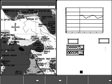
Temp Graph
The Temp Graph Page displays a graph plotting water temperature readings from the transducer over the past 60 minutes as well as current water temperature, boat (paddlewheel) speed, battery voltage and a trip log:
150nm |
|
N-UP |
(RM) |
Temperature |
71.5°F |
|||||
Csr Pos |
N |
26°16.618 |
W 078°44.961 |
74 |
|
|
|
|
|
74 |
|
|
|
|
|
|
|
|
|
||
|
|
|
|
73 |
|
|
|
|
|
73 |
|
|
|
|
72 |
|
|
|
|
|
72 |
|
|
|
|
71 |
|
|
|
|
|
71 |
|
|
|
|
70 |
|
|
|
|
|
70 |
|
|
|
|
69 |
|
|
|
|
|
69 |
|
|
|
|
68 |
|
|
|
|
|
68 |
|
|
|
|
60 |
50 |
40 |
30 |
20 |
10 |
0 |
|
|
|
|
|
|
|
Minutes |
- |
+ |
|
|
|
|
|
Speed |
4.6 kts |
|
13.5 V |
|||
|
|
|
|
Log |
|
|
nm |
|
|
71.5°F |
|
|
|
|
|
|
N |
25°30.000 |
|||
|
|
|
|
|
|
|
|
|||
|
|
|
|
Trip |
|
|
nm |
W 078°30.961 |
||
|
|
|
|
|
|
|
|
28.6ft |
||
|
|
|
|
|
|
|
|
|
|
|
|
|
|
|
286 |
9:35:08am |
|||||
|
|
|
|
|
|
|
|
ft |
|
|
FIND SHIP |
GOTO |
ROUTES |
TRACKS |
PRESENTATION |
-2 |
|
D8699 |
||||||
|
|
|
|
|
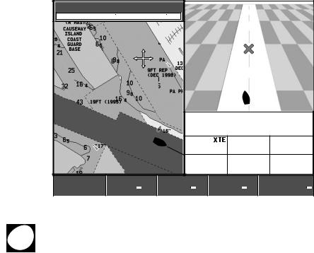
Course Deviation Indicator (CDI)
The Course Deviation Indicator (CDI) gives a graphical representation of your boat’s course in a ‘rolling road’ format.
As you travel towards the target waypoint, the checkered pattern and the waypoint will move down the screen at a rate proportional to your boat’s speed. The steering instructions below the rolling road tell you what correction is needed to maintain your course and arrive at the target waypoint.
Indication arrows are placed either side of the steering instruction, pointing towards the center line. The greater the error the more arrows that appear. Correct your course by steering in the direction indicated by the arrows. If your boat is off track to the degree that it would not be displayed within the rolling road, the boat icon flashes.
Chapter 1: Using the Display |
17 |
|
|
0.5nm |
|
N-UP |
(RM) |
|
|
|
Csr Pos |
N |
25°18.160 |
W 080°19.397 |
|
|
|
|
|
|
|
WPT 0003 |
|
|
|
|
|
>> |
STEER STARBOARD |
|
|
|
|
|
|
|
COG |
HEADING |
|
|
|
0.067nm |
220°T |
225°T |
|
|
|
|
|
WPT BRG |
WPT RNG |
VMG (WPT) |
|
|
|
|
250°T |
0.42nm |
3.1kts |
FIND SHIP |
GOTO |
ROUTES |
TRACKS |
PRESENTATION |
-2 |
|
D7892 |
||||||
|
|
|
|
|
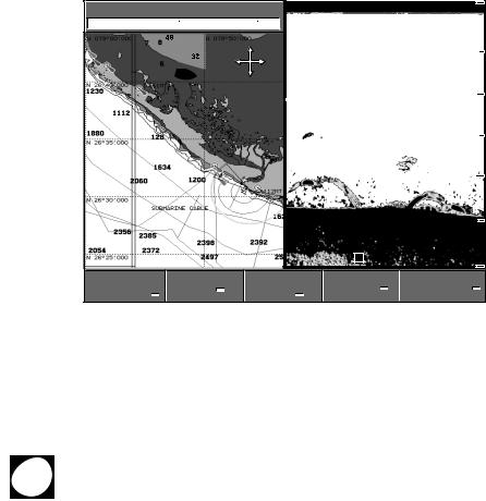
Selecting a Split Window
When the selected page has a split window, the window that is currently active is
ACTIVE bordered in red and the soft key options for that application are displayed.
Pressing the ACTIVE key changes this active highlight to the other window on that page and its associated soft key labels.
Note: When you switch from full chart screen to split screen chart, the split screen is centered at what was the center of the full screen, and the cursor is moved to the center of the split screen.
In the following figure, the fishfinder page is active, so soft keys for that application appear.
18 |
A65 GPS Chartplotter |
|
|
12nm |
|
|
N-UP |
(RM) |
200 kHz |
|
0 |
|
|
Csr Pos |
N |
26°42.618 |
W 078°31.961 |
|
|
|
|
|
|
|
|
|
|
|
ft |
|
|
|
|
|
|
|
|
|
|
|
|
20 |
|
|
|
|
|
|
|
|
|
40 |
|
|
|
|
|
|
|
|
47 |
|
|
|
|
|
|
|
48 8ft |
60 |
|
||
FISHFINDER |
ZOOM |
BOTTOM |
A-SCOPE |
PRESENTATION |
2 |
||||
|
|
|
|
|
- |
||||
SETTINGS |
|
|
LOCK |
|
|
|
D7938 |
||
|
|
|
|
|
|
|
|
|
|
1.4 The Simulator
The A65 display includes a simulator mode, with which you can practice operating your display without data from a GPS antenna or a DSM. Before installation, connect the display to a 12VDC power supply, fused at 4 amps by attaching the red wire from the power lead to positive (+) and the black lead to negative (–).
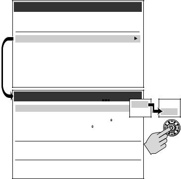
The simulator mode is switched on/off in the System Setup Menu.
1. Press MENU. The main Setup window is displayed.
MENU 2. Use the trackpad (up/down) or rotary knob to highlight System Setup.
3.Press the trackpad (right) to select.
4.Use the trackpad (up/down) or rotary knob to highlight Simulator.
5.Press the trackpad (right) to select.
6.Press the trackpad (up/down) to highlight ON.
7.Press ENTER to accept.
8.Press CANCEL twice to return to the display screen.
The SIMULATOR message flashes at the top of the screen and simulated data is displayed.
Chapter 1: Using the Display |
19 |
|
|
Setup
Chart Setup...
Fishfinder Setup...
System Setup...
Alarms Setup...
GPS Setup...
Compass Setup...
Display Setup...
Diagnostics Menu...
User Card Menu...
System Setup
Simulator |
OFF |
Bearing Mode |
TRUE |
Variation Source |
AUTO (05 E) |
Manual Variation |
00 E |
Language |
ENGLISH (US) |
Settings Reset...
Settings and Data Reset...
Units...
NMEA-Out Setup...
OFF OFF
ON ON
ENTER
D8526-3
To place your simulated boat at a specific geographic location on the chart in Simulation mode:
1.Make sure Simulator mode is set OFF.
2.Place your cursor at the desired location.
3.Switch Simulator mode ON.
20 |
A65 GPS Chartplotter |
|
|
21
Chapter 2: General Operation and
System Setup
2.1 Introduction
This chapter gives details of the general operation of the A65 display and covers the following subjects:
•Using the controls
•Setting up the display
•Presenting information
•Alarms
•Installing and removing CompactFlash (CF) cards
•Saving and retrieving information
•Sharing information using the NMEA protocol
2.2Controls
The controls for the display can be separated into two types:
•Keys
•Soft keys
Keys
Keys enable you to access various system functions or change what you see on the screen:
PWR
PWR Press and release to power ON the display.
After the unit is powered on, press and release as a shortcut to the Brightness setting.
Press and hold to turn the display OFF.
CANCEL
CANCEL Press this key to quit the selected on-screen option when editing data and return to the previous level of soft key labels or menu items.
PAGE
Press to bring up soft keys for selecting the available oneor two-win- dow combinations for Chart and Fishfinder pages.

22 |
A65 GPS Chartplotter |
|
|
ACTIVE
WPTS
MOB
DATA
MENU
ENTER
RANGE
ACTIVE
When a split window page is displayed, press to select which window you wish to work from. The selected window is outlined in red and associated soft key labels are displayed.
WPTS/MOB
Press to display the Waypoints soft keys.
Press again to place a waypoint at the vessel position.
Press and hold to place a Man Overboard (MOB) marker at your current position.
DATA
Press to display soft keys for implementing the various data functions, such as importing/exporting waypoints from/to a CompactFlash card. Also used for sending data to, or receiving data from another instrument or PC using NMEA.
MENU
Press to access the Setup Menu.
Trackpad (outer ring)
The trackpad controls the on-screen cursor and is used to scroll through menu items.
Press the corresponding edge to move the cursor horizontally, vertically or diagonally.
ENTER (middle key)
Press to select an on-screen option, or to return to the previous soft key label or menu level, similar to CANCEL.
RANGE
Press to change the area that is displayed on the screen. Press  to display a smaller area on the screen.
Press  to display a larger area on the screen.
Rotary Knob
Rotate to scroll up/down lists, similar to the trackpad.
Push in to accept a displayed value, similar to the ENTER key.
When editing alpha-numeric values, rotate clockwise to increase the value, rotate counter-clockwise to decrease the value, then push in to accept and move the cursor to the next character.
When a chart is displayed, use to fine tune cursor location. Rotate clockwise to move cursor up and counter-clockwise to move it down. Push in to toggle direction control. Now rotate clockwise to move cursor to the right and counter-clockwise to move it to the left.

Chapter 2: General Operation and System Setup |
23 |
|
|
Soft Keys
There are five soft keys in the bar below the display screen. When a system function key is pressed, the primary soft keys for that function are shown. Pressing a soft key will carry out one of the following functions:
•Select one of the options shown on the soft key label
•Display on-screen information, dialog boxes or menus with new soft keys
•Display additional soft key options
Soft keys sometimes interact with other on-screen controls, such as to edit names, in dialog boxes or to select options in options lists. Soft keys are displayed to control certain items. For example, when you place the cursor over a waypoint, the waypoint soft keys are displayed.
Cursor
The cursor appears on the screen as a white cross. You can move the cursor using the trackpad or rotary knob.
Using the Trackpad
Press the corresponding edge to move the cursor horizontally, vertically or diagonally.
Using the Rotary Knob
Rotate clockwise to move the cursor up and counter-clockwise to move it down. Push in to toggle direction control. Now rotate clockwise to move the cursor to the right and counter-clockwise to move it to the left.
Cursor Info
Cursor Info is a feature that displays the cursor’s position information in a floating data box. When you place the cursor over an object such as a waypoint or chart feature, the cursor turns red and information associated with that object is also displayed. The amount of detail displayed is determined by the Object Information setting in the Chart Setup Menu, which is described on page 31.
To display or hide Cursor Info:
1. Press DATA. The Data soft keys appear.
DATA 2. Press CURSOR INFO. The options toggle between the following selections:
•ON, object data and cursor position information is displayed
•TIMED, object data and cursor position information are displayed for three seconds and then disappear
•OFF, object data and cursor position information are not displayed
24 |
A65 GPS Chartplotter |
|
|
2.3 Status Bar
The Status Bar provides current information about the chart application.
Half Screen
|
12nm |
N-UP |
(RM) |
|
|
Csr Pos |
N 25°18.160 |
W 080°19.397 |
|
Full Screen |
|
|
|
|
|
12nm |
|
North-Up |
|
Csr Pos N 25°18.160 W 080°19.397
Top Line
(Relative Motion)
090°T |
0.67nm |
D8995-1
•Chart Range
This represents the distance from the top to the bottom of screen at the current zoom level (refer to “Zoom in/out“ on page 67). Range rings are drawn at intervals equal to 1/4 of this value.
•Orientation
This reports the orientation mode currently displayed: Head Up, North Up, or Course Up. When in split screens, these appear as H-UP, N-UP, and C-UP, respectively (see page 88).
•Relative Motion mode
This indicates that the chart is in Relative Motion mode, which is invoked at power-up or when you press FIND SHIP. When you move relocate the cursor, Relative Motion is broken and the indicator appears in amber text and enclosed in parentheses—(Relative Motion). When in split windows, these appear as RM and (RM), respectively. Relative Motion is described in more detail on page 89.
Bottom Line
•Position / Csr Pos
When in Relative Motion mode, this field displays the boat’s Position. When Relative Motion is suspended, the cursor position (Csr Pos) and bearing & range from the boat are shown.
Note: Measurements in the Status Bar are displayed in the Distance Units set in the Units parameter of the System Setup menu.When zooming in and the value becomes less than 0.5 mile or 0.5 kilometer, the distance unit converts to feet or meters, respectively.

Chapter 2: General Operation and System Setup |
25 |
|
|
2.4 Displaying Control Information on the Screen
Information connected with controls is shown on your screen in the following ways:
•Soft Keys
•Dialog boxes
•Pop-Up messages
•Database lists
Soft Keys
These are the primary means of control of the display. See “Soft Keys“ on page 23 for a detailed explanation.
Dialog Boxes
Dialog boxes enable editing of objects stored on the display, such as a waypoint. Objects can be selected on-screen or from the appropriate list. Dialog box information can be edited using the soft keys, the rotary knob or the trackpad. For details, see “Editing a Waypoint“ on page 53.
Edit Waypoint
Symbol:
Name: WPT 0005
Latitude: N 26 16.496
Longitude: W 080 03.907
Comment:
N 26 16.496
D8079-2
Pop-up Messages
Pop-up messages, can be of two types:
•Information. These messages appear for a set period of time and alert you to something which is happening, such as a function not being available. These messages cannot be edited, and some may be a prompt that require a response.
•Alarm messages. See “Alarm Setup Menu“ on page 35 for more information.

26 |
A65 GPS Chartplotter |
|
|
Database Lists
Database lists contain information that have been added to the display memory, such as lists provided for waypoints and routes. You can scroll through a database list using the trackpad to highlight a particular entry. Entries within a database list can be selected for editing (for example, erase or edit the name of a waypoint).
2.5 Setting up the Display
You can set up the display so that the applications being used are presented in the way that suits how you work. This section shows you how to access and change these settings.
Note: All non-sounder setting changes (except Brightness and Relative Motion) are retained when the unit is powered off using the PWR key.However, there is a one-minute delay from the time you make the setting change to when the A65 places it in memory.If power is removed from the unit without using the PWR key less than one minute after making a change, the setting is lost.
To access and edit the Setup menu:
1. Press MENU. The Setup menu is displayed.
Setup
Chart Setup...
Fishfinder Setup...
System Setup...
Alarms Setup...
GPS Setup...
Display Setup...
Diagnostics Menu...
User Card Menu...
The Setup Menu is contains the following sub-menus:
D7901-2
•Chart Setup
•Fishfinder Setup. For details please refer to the DSM25 Handbook.
•System Setup
•Alarms Setup
•GPS Status
•Display Setup
•System Diagnostics
•User Card Setup

Chapter 2: General Operation and System Setup |
27 |
|
|
2.Use the trackpad or the rotary knob to highlight the menu items you wish to access.
When you first power on your display the default values are used. The tables in following sections show the sub-menus, default settings and options available.
2.6 Chart Setup Menu
The setup for your chartplotter and its cartography can be changed from the standard configuration to suit your particular needs. Although you will probably only do this when you first use the chartplotter, you may decide to make subsequent adjustments after you become more familiar with the system. Any settings that you change are retained even when you power off.
To select the Chartplotter Setup menus, press MENU and then select Chart Setup.
1.Press the trackpad (right). The menu changes to show you the available options or shows a sub-menu.
|
Chart Setup |
|
ENTER |
Chart Display |
DETAILED |
|
Chart Grid |
ON |
|
Chart Text |
ON |
|
Chart Text Size |
LARGE |
|
Chart Boundaries |
ON |
|
Spot Soundings |
ON |
|
Safety Contour |
7ft |
|
Depth Contour |
ALL |
|
Nav. Marks |
ON |
|
Nav. Marks Symbols |
INTERNATIONAL |
|
Light Sectors |
ON |
|
Caution & Routing Data |
OFF |
|
Marine Features |
ON |
|
Land Features |
ON |
|
More... |
|
D8227-2
2. Press trackpad (down) or rotate the knob to highlight the desired option.

28 |
A65 GPS Chartplotter |
|
|
ENTER
O R
Chart Setup |
Chart Display |
DETAILED |
Chart Grid |
ON |
Chart Text |
ON |
Chart Text Size |
LARGE |
Chart Boundaries |
ON |
Spot Soundings |
ON |
|
|
Safety Contour |
7ft |
Depth Contour |
ALL |
Nav. Marks |
ON |
Nav. Marks Symbols |
INTERNATIONAL |
Light Sectors |
ON |
Caution & Routing Data |
OFF |
Marine Features |
ON |
Land Features |
ON |
More... |
|
D8228-2
3.Press the trackpad (right) to select this item. The menu changes to show you the available options.
4.Use the trackpad or the rotary knob to change the value of the field.
Chart Setup |
|
Chart Display |
DETAILED |
|
|
ENTER |
Chart Grid |
ON |
|
|
|
Chart Text |
ON |
|
|
|
Chart Text Size |
LARGE |
|
|
|
Chart Boundaries |
ON |
OFF |
OFF |
|
|
|||
|
Spot Soundings |
ON |
7ft |
7ft |
|
|
|||
|
Safety Contour |
7ft |
16ft |
16ft |
|
|
|||
|
Depth Contour |
ALL |
33ft |
33ft |
|
|
|||
|
Nav. Marks |
ON |
66ft |
66ft |
|
|
|||
|
Nav. Marks Symbols |
INTERNATIONAL |
|
|
|
Light Sectors |
ON |
|
|
|
Caution & Routing Data |
OFF |
|
ENTER |
|
|
|
||
|
Marine Features |
ON |
|
|
|
Land Features |
ON |
|
|
|
More... |
|
-2 |
|
|
|
|
D8229 |
|
5.Press ENTER to save your selection or CANCEL to retain the previous setting.
Chapter 2: General Operation and System Setup |
29 |
|
|
6.Repeat these steps until you have completed setting up the display with your preferences.
7.Press CANCEL to return to the default screen. This may require pressing the key more than once.
Depth Contour |
|
Safety Contours (shaded areas) |
||
|
|
|
|
|
|
|
|
|
|
D8822-2 |
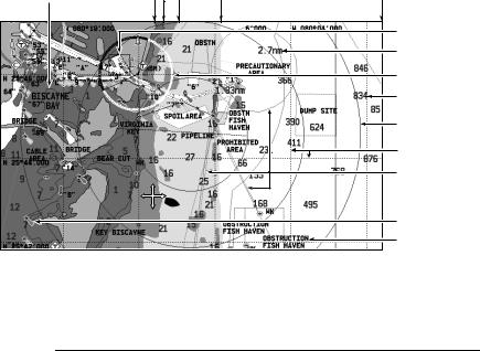
Chart Boundary
Range Ring Distance
Light Sector
Spot Sounding
Range Ring
Chart Grid
Caution and
Routing Data
Nav Mark
Chart Text
Chart Setup
The following describes the options found in the Chart Setup menu.
FUNCTION |
OPTIONS |
Description |
(Default in bold) |
|
|
Chart Display |
SIMPLE |
The level of detail shown on the chart. |
DETAILED |
|
EXTRA DETAILED |
|
|
Chart Grid |
OFF |
Grid lines of latitude and longitude. |
ON |
|
|
Chart Text |
OFF |
Text appearing on the chart, such as place names. |
ON |
|
|
Chart Text Size |
SMALL |
Size of text appearing on the chart. |
LARGE |
|
|
Chart Boundaries |
OFF |
The line indicating the boundary of the chart. |
ON |
|
|
30 |
|
A65 GPS Chartplotter |
|
|
|
|
|
|
|
|
|
|
FUNCTION |
OPTIONS |
|
|
Description |
(Default in bold) |
|
|
|
|
|
|
Spot Soundings |
OFF |
|
|
Number on the chart indicating depth. |
ON |
|
|
|
|
|
|
Safety Contour |
OFF |
|
|
Areas with depths shallower that the specified value are shaded |
7ft |
|
|
in a different color than those areas with depths greater than |
16ft |
|
|
the specified value. The contour is always drawn at or deeper |
33ft |
|
|
than the selected depth. |
66ft |
|
|
|
|
|
|
Depth Contour |
OFF |
|
|
Outlines an area that is located at the specified depth. |
16ft |
|
|
|
33ft |
|
|
|
66ft |
|
|
|
ALL |
|
|
|
|
|
|
Nav. Marks |
OFF |
|
|
Navigation marks. |
ON |
|
|
|
|
|
|
Nav. Marks Symbols |
INTERNATIONAL |
|
|
The set of symbology used for navigation marks. |
US |
|
|
Corresponds to paper charts. |
|
|
|
|
|
|
|
Light Sectors |
OFF |
|
|
The sector of light cast by a fixed beacon. |
ON |
|
|
|
|
|
|
Caution & Routing Data |
OFF |
|
|
Magenta-colored lines indicating route for safe passage and |
ON |
|
|
outlining areas to avoid. |
|
|
|
|
|
|
|
Marine Features |
OFF |
|
|
The cartographic features that are displayed on the water. |
ON |
|
|
|
|
|
|
Land Features |
OFF |
|
|
The cartographic features that are displayed on the land. |
ON |
|
|
|
|
|
Navigate to ‘More’ and right-press the trackpad to access additional selections.
Loading...