


 Loading...
Distributed by
Any reference to Raytheon or RTN in this manual should be interpreted as Raymarine. The names Raytheon and RTN are owned by the
Raytheon Company.
ST4000+
Wheel & Tiller
Autopilots
Owner’s
Handbook
Document number: 81131-6
Date: August 2001
ii |
ST4000+ Wheel & Tiller Autopilots: Owner’s Handbook |
Autohelm, HSB (High Speed Bus), SailPilot, SeaTalk and SportPilot are registered trademarks of Raymarine Ltd.
Raymarine, AST (Advanced Steering Technology), AutoAdapt, AutoLearn, AutoRelease, AutoSeastate, AutoTack, AutoTrim, FastTrim, GyroPlus, RayGyro, RayPilot and WindTrim are trademarks of Raymarine Ltd.
Handbook contents © Raymarine Ltd 2001.

Preface |
iii |
ST4000+ autopilot system layout |
|
|
Wheel drive |
|
OR |
Tiller drive |
|
|
Boat's electrical |
|
distribution panel |
|
ST4000+ |
Fluxgate compass |
control unit |
|
Rudder position sensor |
|
(optional fit for wheel pilot only) |
SeaTalk instrument |
|
|
NMEA |
|
instrument |
|
or navigator |
|
D5332-1 |
iv |
ST4000+ Wheel & Tiller Autopilots: Owner’s Handbook |

Preface |
|
v |
Contents |
|
|
About this handbook ........................................................... |
ix |
|
Important Information ......................................................... |
x |
|
Warranty ...................................................................................... |
x |
|
Safety notices .............................................................................. |
x |
|
EMC conformance ..................................................................... |
xi |
|
Handbook information ............................................................... |
xi |
|
Chapter 1: Introduction ............................................................ |
1 |
|
1.1 |
Features ..................................................................................... |
1 |
1.2 |
Extended systems ...................................................................... |
2 |
Chapter 2: Basic Operation ....................................................... |
3 |
|
2.1 |
Using the control unit ................................................................ |
4 |
|
Key functions ............................................................................ |
4 |
|
Display layout ........................................................................... |
5 |
2.2 |
Using Auto mode ...................................................................... |
6 |
|
Engaging the autopilot (Auto mode) ......................................... |
6 |
|
Disengaging the autopilot (Standby mode) .............................. |
7 |
|
Changing course in Auto mode ................................................. |
8 |
|
Dodging obstacles in Auto mode .............................................. |
8 |
|
Returning to the previous locked heading (LAST HDG) ......... |
9 |
|
Automatic tack (AutoTack) .................................................... |
10 |
|
Making major course changes ................................................ |
10 |
|
Gusting conditions .................................................................. |
11 |
2.3 |
Adjusting autopilot performance ............................................ |
12 |
|
Changing the response level (AutoSeastate) .......................... |
12 |
|
Changing the rudder gain ........................................................ |
13 |
2.4 |
Autopilot alarms ..................................................................... |
14 |
|
Responding to alarms .............................................................. |
14 |
2.5 |
Adjusting display and keypad lighting ................................... |
18 |
Chapter 3: Advanced Operation ............................................ |
19 |
|
3.1 |
Using Track mode ................................................................... |
20 |
|
Selecting Track mode ............................................................. |
20 |
|
Exiting Track mode ................................................................. |
22 |
|
Cross track error ...................................................................... |
22 |
|
Tidal stream compensation ..................................................... |
23 |
|
Waypoint arrival and advance ................................................. |
24 |
|
Dodges in Track mode ............................................................ |
25 |
|
Safety in Track mode .............................................................. |
25 |

vi |
ST4000+ Wheel & Tiller Autopilots: Owner’s Handbook |
|
3.2 |
Using Wind Vane mode .......................................................... |
27 |
|
Selecting Wind Vane mode ..................................................... |
27 |
|
Exiting Wind Vane mode ........................................................ |
28 |
|
Adjusting the locked wind angle ............................................. |
28 |
|
Returning to the previous apparent wind angle |
|
|
(LAST WND) ......................................................................... |
28 |
|
Dodges in Wind Vane mode .................................................... |
29 |
|
Wind shift alarm ...................................................................... |
29 |
|
Using AutoTack in Wind Vane mode ...................................... |
30 |
|
Operating hints for Wind Vane mode ...................................... |
30 |
3.3 |
Displaying data pages ............................................................. |
31 |
Chapter 4: Maintenance & Fault Finding .............................. |
33 |
|
4.1 |
Fault finding ............................................................................ |
34 |
4.2 |
General maintenance .............................................................. |
36 |
|
Wheel drive ............................................................................. |
36 |
|
Control unit ............................................................................. |
38 |
|
EMC advice ............................................................................ |
39 |
4.3 |
Product support ....................................................................... |
40 |
|
Software version ..................................................................... |
40 |
Chapter 5: Installing the ST4000+ .......................................... |
43 |
|
5.1 |
Planning the installation ......................................................... |
44 |
|
Tools required ......................................................................... |
44 |
|
EMC installation guidelines ................................................... |
46 |
5.2 |
Control unit ............................................................................. |
48 |
|
Location .................................................................................. |
48 |
|
Mounting procedure ............................................................... |
49 |
|
Cable connectors ..................................................................... |
51 |
|
Power supply connection ........................................................ |
51 |
|
SeaTalk connections ............................................................... |
52 |
|
NMEA connections ................................................................ |
53 |
5.3 |
Fluxgate compass ................................................................... |
55 |
|
Location .................................................................................. |
55 |
|
Mounting ................................................................................ |
57 |
|
Connecting to the control unit ................................................. |
58 |
5.4 |
Tiller drive (tiller pilots only) .................................................. |
59 |
|
Critical dimensions ................................................................. |
59 |
|
Basic installation ..................................................................... |
60 |
|
Installation accessories ........................................................... |
61 |
|
Connecting to the control unit ................................................. |
68 |

Preface |
vii |
5.5 Wheel drive (wheel pilots only) .............................................. |
70 |
Installation stages .................................................................... |
70 |
Drilling the spoke clamp holes ................................................ |
71 |
Securing the wheel drive to the wheel ..................................... |
74 |
Attaching the pedestal bracket ................................................ |
75 |
Connecting to the control unit ................................................. |
79 |
5.6 Rudder position sensor (wheel pilot option) ........................... |
81 |
Ensuring correct alignment ..................................................... |
81 |
Securing the sensor to the boat ................................................ |
83 |
Attaching the sensor to the tiller arm ....................................... |
83 |
Checking alignment ................................................................ |
84 |
Connecting to the control unit ................................................. |
84 |
Chapter 6: Setting-up the ST4000+ ........................................ |
85 |
6.1 Functional test ......................................................................... |
86 |
Switch on ................................................................................ |
86 |
Autopilot steering direction .................................................... |
86 |
Checking connections ............................................................. |
88 |
6.2 Check rudder sensor operation (if fitted) ................................ |
90 |
6.3 Initial sea trial .......................................................................... |
91 |
Overview ................................................................................ |
91 |
Correcting the compass deviation .......................................... |
92 |
Adjusting the heading alignment ............................................ |
95 |
Checking autopilot operation .................................................. |
95 |
Checking the rudder gain ........................................................ |
96 |
6.4 Autopilot calibration techniques ............................................. |
98 |
Step 1 - Switch on ancillary equipment ................................... |
98 |
Step 2 - Apply initial settings .................................................. |
98 |
Step 3 - Adjust the rudder damping ......................................... |
99 |
Step 4 - Adjust the rudder gain ................................................ |
99 |
Step 5 - Adjust the AutoTrim setting ....................................... |
99 |
Step 6 - Further adjustments .................................................... |
99 |
Chapter 7: Customizing the ST4000+ .................................. |
101 |
7.1 User setup .............................................................................. |
102 |
Compass deviation correction (SWING COMPASS) .......... |
102 |
Deviation display (DEVIATION) ........................................ |
102 |
Heading alignment (ALIGN HDG) ...................................... |
102 |
Heading mode (HDG MAG/TRU) ....................................... |
102 |
Bar selection (RUDD BAR/STEER BAR/NO BAR) .......... |
104 |
Data pages 1-7 (DATA PAGE) .............................................. |
104 |

viii |
ST4000+ Wheel & Tiller Autopilots: Owner’s Handbook |
|
|
7.2 Dealer setup .......................................................................... |
106 |
|
Calibration lock (CAL LOCK) ............................................. |
108 |
|
Pilot type (4000 WHL/TILL) ............................................... |
108 |
|
Rudder gain (RUDD GAIN) ................................................. |
108 |
|
Response level (RESPONSE) .............................................. |
108 |
|
Turn limit (TURN RATE) ..................................................... |
108 |
|
Rudder alignment (ALIGN RUD) ........................................ |
108 |
|
Rudder limit (RUD LIMIT) .................................................. |
109 |
|
Off course alarm (OFF COURSE) ........................................ |
109 |
|
AutoTack angle (AUTOTACK) ........................................... |
109 |
|
AutoTrim (AUTOTRIM) ..................................................... |
110 |
|
Drive type (DRIVE TYP) ..................................................... |
110 |
|
Magnetic variation (VARIATION) ....................................... |
110 |
|
AutoAdapt (AUTOADAPT) ................................................. |
111 |
|
Latitude (LATITUDE) ........................................................... |
111 |
|
Rudder damping (RUDD DAMP) ........................................ |
112 |
|
Cruise speed (CRUISE SP) .................................................. |
112 |
|
Specifications .................................................................... |
113 |
|
Glossary .............................................................................. |
115 |
|
Index ................................................................................... |
117 |
Preface |
ix |
About this handbook
Welcome to the handbook for the ST4000+ wheel and tiller autopilot systems. This handbook contains two main parts:
Part 1: Using the ST4000+ Autopilot
1 |
Chapter 1: Introduction |
page 1 |
|
Introduces the autopilot, its features and its use. |
|||
|
|
||
|
|
|
|
|
|
|
|
|
Chapter 2: Basic Operation |
|
|
2 |
Covers basic autopilot operation: using Auto mode, |
page 3 |
|
interpreting alarms, adjusting autopilot performance and |
|||
|
|
||
|
changing the control unit lighting. |
|
|
|
|
|
|
|
|
|
|
3 |
Chapter 3: Advanced Operation |
|
|
Explains how to use Track and Wind Vane modes, and |
page 19 |
||
|
display data pages. |
|
|
|
|
|
|
|
|
|
|
|
Chapter 4: Maintenance & Fault Finding |
|
|
4 |
Provides general maintenance procedures and |
page 33 |
|
information to help you resolve problems you may |
|||
|
|
||
|
encounter with the autopilot |
|
|
|
|
|
|
Part 2: Installing the ST4000+ Autopilot |
|
||
|
|
|
|
5 |
Chapter 5: Installing the ST4000+ |
page 43 |
|
Explains how to install your autopilot and its components. |
|||
|
|
||
|
|
|
|
|
|
|
|
6 |
Chapter 6: Setting-up the ST4000+ |
|
|
Covers functional testing and dockside procedures after |
page 85 |
||
|
installation, and initial sea trials. |
|
|
|
|
|
|
|
|
|
|
7 |
Chapter 7: Customizing the ST4000+ |
|
|
Provides details on adjusting the autopilot settings to suit |
page 101 |
||
|
your boat. |
|
|
|
|
|
|
At the end of this handbook we have included product specifications, a glossary and index, and templates for installing different parts of the system.
Note: This handbook contains important information about installing, using and maintaining your new Raymarine product. To get the best from the product, please read this handbook thoroughly.
x |
ST4000+ Wheel & Tiller Autopilots: Owner’s Handbook |
Important Information
Warranty
To register your new Raymarine product, please take a few minutes to fill out the warranty card. It is important that you complete the owner information and return the card to us to receive full warranty benefits.
Safety notices
WARNING: Product installation
This equipment must be installed and operated in accordance with the instructions contained in this handbook. Failure to do so could result in poor product performance, personal injury and/or damage to your boat.
WARNING: Electrical safety
Make sure the power supply is switched off before you make any electrical connections.
WARNING: Calibration
We supply this product calibrated to default settings that should provide stable performance for most boats. To ensure optimum performance on your boat, you must complete Chapter 6:
Setting-up the ST4000+ before use.
WARNING: Navigation aid
Although we have designed this product to be accurate and reliable, many factors can affect its performance. As a result, it should only be used as an aid to navigation and should never replace common sense and navigational judgement. Always maintain a permanent watch so you can respond to situations as they develop.
Your Raymarine autopilot will add a new dimension to your boating enjoyment. However, it is the skipper’s responsibility to ensure the safety of the boat at all times by following these basic rules:
•Ensure that someone is present at the helm AT ALL TIMES, to take manual control in an emergency.
Preface |
xi |
•Make sure that all members of crew know how to disengage the autopilot.
•Regularly check for other boats and any obstacles to navigation – no matter how clear the sea may appear, a dangerous situation can develop rapidly.
•Maintain an accurate record of the boat’s position by using either a navigation aid or visual bearings.
•Maintain a continuous plot of your boat’s position on a current chart. Ensure that the locked autopilot heading will steer the boat clear of all obstacles. Make proper allowance for tidal set – the autopilot cannot.
•Even when your autopilot is locked onto the desired track using a navigation aid, always maintain a log and make regular positional plots. Navigation signals can produce significant errors under some circumstances and the autopilot will not be able to detect these errors.
EMC conformance
All Raymarine equipment and accessories are designed to the best industry standards for use in the recreational marine environment. The design and manufacture of Raymarine equipment and accessories conform to the appropriate Electromagnetic Compatibility (EMC) standards, but correct installation is required to ensure that performance is not compromised.
Handbook information
To the best of our knowledge, the information in this handbook was correct when it went to press. However, Raymarine cannot accept liability for any inaccuracies or omissions it may contain. In addition, our policy of continuous product improvement may change specifications without notice. As a result, Raymarine cannot accept liability for any differences between the product and the handbook.
xii |
ST4000+ Wheel & Tiller Autopilots: Owner’s Handbook |

Part 1:
Using the
ST4000+
ST4000+ the Using 1: Part

Part 1: Using the ST4000+
Chapter 1: Introduction |
1 |
Chapter 1: Introduction
Introduction 1
-1 D5460
1.1 Features
The Raymarine ST4000 Plus (ST4000+) is a SeaTalk® compatible autopilot available in versions suitable for boats with either tiller or wheel steering systems. This autopilot system will steer your boat to a heading automatically, accurately and reliably.
The ST4000+ has four main operating modes:
1.Standby: autopilot off (see page 7)
2.Auto: autopilot engaged and locked onto a heading (see page 6)
3.Track: autopilot engaged and maintaining a track between two waypoints created using a navigation system (see page 20)
4.Wind Vane: autopilot engaged and maintaining a course relative to an apparent wind angle (see page 27)
The ST4000+ also provides the following features:
•automatic tack facility (AutoTack) in Auto and Wind Vane modes
•automatic compass deviation correction
•Northerly/Southerly heading compensation
•automatic heading deadband – seastate control
•waypoint advance feature
•setup and calibration options to optimize performance on your boat

1 Introduction
2 |
ST4000+ Wheel & Tiller Autopilots: Owner’s Handbook |
1.2 Extended systems
The ST4000+ is compatible with all other SeaTalk instruments. You can connect it to additional fixed or handheld SeaTalk autopilot control units located at secondary steering and control positions (see page 52).
You can also use the ST4000+ autopilot with any navigator (GPS, Decca, Loran) or wind instrument that transmits data in the internationally-accepted National Marine Electronics Association (NMEA) 0183 format.
The ST4000+ can display SeaTalk and NMEA instrument data in a user-defined selection of data pages. When you are using the ST4000+ to repeat instrument data, it shows a ‘pop-up’ pilot page for 5 seconds whenever you make a change in autopilot control.
The ST4000+ can share all data transmitted from SeaTalk instruments:
•it can use wind information from a SeaTalk wind instrument for wind trim steering in Wind Vane mode without the need for a separate vane
•it can use track information from a SeaTalk navigation instrument to provide waypoint control in Track mode
•it can use boat speed from a SeaTalk speed instrument to optimize track-keeping performance
Rudder position sensor (wheel drives only)
On wheel drive systems you can fit a rudder position sensor to improve the wheel pilot’s performance (see page 81). This is particularly advisable if your boat’s steering system has significant backlash, or you require optimum performance from a mechanical or cable steering system. By using the information from the rudder angle sensor, the ST4000+ will also be able to show the true rudder angle in Standby and Auto modes.
Note: You MUST add a rudder position sensor if fitting the ST4000+ to a hydraulic steering system.
Chapter 2: Basic Operation |
3 |
Chapter 2: Basic Operation
The sections in this chapter explain how to use the basic functions on your autopilot:
2.1 |
Using the control unit |
|
|
|
Summarizes the key functions and screen layout on the |
page 4 |
|
|
|
|
ST4000+ control unit. |
|
|
|
|
|
|
|
|
|
|
|
|
|
2.2 |
Using Auto mode |
|
|
|
Provides instructions for engaging/disengaging the |
page 6 |
|
|
|
|
||||
|
autopilot and using Auto mode. |
|
|
|
|
|
|
|
2 |
|
|
|
|
|
|
Adjusting autopilot performance |
|
|
|
2.3 |
|
|
Basic |
|
Making temporary adjustments to response level and |
page 12 |
|
||
|
rudder gain to enhance autopilot performance. |
|
|
Operation |
|
|
|
|
|
|
|
|
|
|
2.4 |
Describes how to recognize and respond to the |
page 14 |
|
|
|
Autopilot alarms |
|
|
|
|
autopilot alarms. |
|
|
|
|
|
|
|
|
|
|
|
|
|
2.5 |
Adjusting display and keypad lighting |
|
|
|
|
|
|
||
Explains how to change the lighting on the control unit |
page 18 |
|
|
|
|
display and keypad. |
|
|
|
|
|
|
|
|
CAUTION: Important note for wheel drive systems
After each trip, flush inside the drive unit by inserting a hose pipe in the free slot on the back cover. This will prevent any build-up of salt on the drive ring and bearings.

4 ST4000+ Wheel & Tiller Autopilots: Owner’s Handbook
2.1 Using the control unit
Key functions
|
• The autopilot always powers up in Standby mode. |
|||
|
• You control the autopilot by pressing the buttons on the control |
|||
|
unit. The control unit confirms each button press with a short |
|||
|
beep. |
|
|
|
|
• You access the main functions by pressing a single key: |
|||
|
• for example, when the autopilot is operating you can make |
|||
|
course changes using the -1, +1, -10 and +10 keys |
|||
|
||||
|
• To access other functions you need to press two keys together: |
|||
Operation |
• for example, when the autopilot is operating you make an |
|||
AutoTack to port by pressing the -1 and -10 keys together |
||||
|
||||
|
• You can return to manual steering at any time by pressing |
|||
2 Basic |
standby and disengaging the autopilot (see page 7). |
|||
|
|
|
||
|
|
|
|
|
|
|
-1 plus +1 |
|
|
|
|
Press for Response level |
|
|
|
-1 plus -10 |
Press for 1 second |
+1 plus +10 |
|
|
Press together |
for Rudder Gain |
Press together |
|
|
for AutoTack |
|
for AutoTack |
|
|
to port |
|
to starboard |
|
|
DISP |
|
TRACK |
|
|
Press for |
|
Press for Track |
|
|
Data Page |
|
mode from Auto |
|
|
Press for 1 second |
|
Press to accept |
|
|
for lamp control |
|
waypoint advance |
|
Press for 1 second to skip waypoint
STANDBY
Press for Standby mode
Press and hold for User and Dealer setup modes
Course change keys
Port 1˚ Starboard 1˚
Port 10˚ Starboard 10˚
STANDBY plus AUTO
Press for Wind Vane mode Press for 1 second for Last Wind Press again to accept Last Wind
AUTO
Press for Auto mode
Press for 1 second for Last Heading
Press again to accept Last Heading
D3447-2

Chapter 2: Basic Operation |
5 |
Display layout
The ST4000+ autopilot display provides the following information:
Variable text region (up to 9 characters/digits)
Heading indicators
Distance units
Response level indicator
Autopilot mode indicators
Port and Starboard direction-to-steer indicators
Calibration mode indicator
Rudder or Steer direction indicator
(bar graph in 2˚ increments)
D3316-2
•If the display shows no distance unit all distances are in kilometres (Km), otherwise distances are in nautical miles (nm) or statute/land miles (SM).
•The bar graph at the bottom of the screen is normally a direction-to-steer indicator (you can change this in User setup, see page 104). The information displayed on the bar graph varies according to the autopilot mode:
Autopilot mode |
Information displayed on bar graph |
|
|
Standby |
Rudder bar (only if a rudder position sensor is fitted) |
|
|
Auto |
Heading error bar |
|
|
Track |
Cross track error (XTE) bar, in 0.02 nm increments |
|
|
Wind Vane |
Wind angle error bar |
|
|
Operation Basic 2
2 Basic Operation
6 |
ST4000+ Wheel & Tiller Autopilots: Owner’s Handbook |
2.2Using Auto mode
Engaging the autopilot (Auto mode)
1.Steady the boat on the required heading.
2.Wheel Pilot: Engage the wheel drive clutch by rotating the clutch lever clockwise (so the lever engages fully onto the locating pip). Tiller Pilot: Place the pushrod end over the tiller pin. If necessary, extend or retract the pushrod using the -1, +1, -10 and +10 keys.
WARNING: Wheel drive clutch
Always reach AROUND (not through) the wheel to operate the wheel drive clutch lever.
.
Wheel pilot
Engage the clutch on the wheel pilot
Tiller pilot
a
 b
b
Use these keys to |
|
extend or retract the pushrod |
D5341-1 |
3.Press auto:
• in Auto mode, the display shows the locked autopilot heading
D3560-2

Chapter 2: Basic Operation |
7 |
CAUTION:
Autopilot course control makes it easier to sail a boat, but it is NOT a substitute for good seamanship. ALWAYS maintain a permanent watch, no matter how clear the sea appears to be.
Disengaging the autopilot (Standby mode)
1.Press standby.
•in Standby mode, the display shows the boat’s current compass heading.
D3561-2
2.Disengage the autopilot to return to hand steering:
•Wheel Pilot: Disengage the wheel drive clutch by rotating the clutch lever anti-clockwise (so the lever engages fully onto the locating pip).
•Tiller Pilot: Remove the drive unit from the tiller pin. If required, retract the push rod using -1, +1, -10 and +10 keys.
3.The last heading is memorized and can be recalled (see page 9).
CAUTION: Wheel drive systems
On wheel drive systems, always make sure that the clutch is
FULLY DISENGAGED before you leave the boat.
Operation Basic 2
8 |
ST4000+ Wheel & Tiller Autopilots: Owner’s Handbook |
Changing course in Auto mode
In Auto mode, use the -1 and -10 (port) and +1 and +10 (starboard) keys to change the locked heading in steps of 1° or 10°. For example: press -10 three times for a 30° course change to port.
2 Basic Operation
Port |
Starboard |
or |
or |
D3320-2
Dodging obstacles in Auto mode
To avoid an obstacle when your boat is under autopilot control:
1.Select a course change in the appropriate direction. For example, press -10 three times for a 30° dodge to port.
Obstacle
Original
course
Dodge
D3303-2
2.When safely clear of the obstacle, you can either:
•reverse the previous course change (for example, press +10 three times), or
•return to the previous locked heading (LAST HDG)

Chapter 2: Basic Operation |
9 |
Returning to the previous locked heading (LAST HDG)
If you have steered the boat away from the selected locked heading for any reason (for example, executing a dodge maneuver or selecting Standby), you can return to the previous locked heading as follows:
1.Press auto for 1 second. The display shows the previous locked heading (LAST HDG?) for 7 seconds.
SECOND
D3562-2
Note: The direction-to-steer indicator shows the direction the boat will turn.
2.To accept the previous heading, and resume this course, press auto within this 7 second period.
Obstacle
Resumed
course
Original
course
Dodge
D5431-1
Operation Basic 2
Note: If you do not press auto while the display is flashing, the autopilot will maintain the current heading.
2 Basic Operation
10 |
ST4000+ Wheel & Tiller Autopilots: Owner’s Handbook |
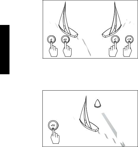
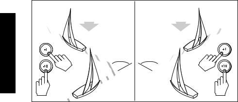
Automatic tack (AutoTack)
The ST4000+ has a built in automatic tack facility (AutoTack) that turns the boat through a pre-determined angle in the required direction. The default AutoTack angle is 100°, but you can adjust this in Dealer setup (see page 109).
•to AutoTack to port: press the -1 and -10 keys together
•to AutoTack to starboard: press the +1 and +10 keys together
AutoTack - Port |
AutoTack - Starboard |
|
|
Wind |
Wind |
|
|
|
AutoTack |
AutoTack |
angle |
angle |
D5399-1
Making major course changes
CAUTION:
Only make major course changes when steering MANUALLY. This ensures that the boat will safely clear any obstructions or other boats, and you can take into account the changed wind and sea conditions on the new heading before engaging the autopilot.
Large course changes which change the apparent wind direction can produce large trim changes. When a sudden trim change occurs (for example due to weather helm or sail imbalance) there will be a delay of up to one minute before the automatic trim applies rudder to restore the locked heading.
In these situations, the autopilot will not immediately assume the new automatic heading, and will only settle onto course when the automatic trim has been fully established. To eliminate this problem, use the following procedure to make major course changes:

Chapter 2: Basic Operation |
11 |
1.Note the required new heading.
2.Select standby for manual steering, so you can bring the boat to the new heading MANUALLY.
3.Select auto: allow the boat to settle onto course, then bring the boat to the final course in 1° steps using the -1 or +1 keys
Gusting conditions
In gusting conditions, the course may tend to wander slightly, particularly if the sails are badly balanced. If you take the following precautions, the autopilot will be able to maintain competent control even in gale force conditions:
•You can significantly improve course keeping by improving the sail balance:
•do not allow the boat to heel over excessively
•ease the mainsheet traveller to leeward to reduce heeling and weather helm
•if necessary, reef the mainsail a little early
•In very strong winds and large seas, you should avoid sailing with the wind dead astern:
•ideally, bring the wind at least 30° away from a dead run
•in severe conditions, you may also need to remove the mainsail and sail under headsail only
Operation Basic 2
2 Basic Operation
12 |
ST4000+ Wheel & Tiller Autopilots: Owner’s Handbook |
2.3 Adjusting autopilot performance
During normal autopilot operation in any mode you can make temporary adjustments to:
•response level
•rudder gain
Note: You will lose these temporary changes to response level and rudder gain whenever the system is powered off then on again. You can make permanent adjustments in Dealer setup (see page 108).
Changing the response level (AutoSeastate)
The response level controls the relationship between the autopilot’s course keeping accuracy and the amount of helm/drive activity.
•Response Level 1: AutoSeastate on (Automatic deadband)
This setting causes the autopilot to gradually ignore repetitive boat movements and only react to true variations in course. This provides the best compromise between power consumption and course keeping accuracy, and is the default calibration setting.
•Response Level 2: AutoSeastate off (Minimum deadband)
This setting provides the tightest course keeping possible. However, tighter course keeping results in increased power consumption and drive unit activity.
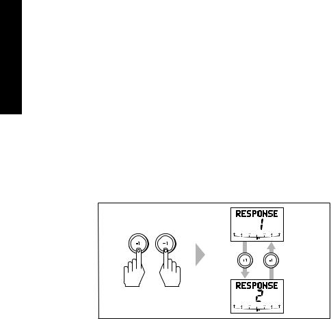
To make a temporary change to the response setting:
1.Display the RESPONSE screen by pressing the -1 and +1 keys together momentarily.
D3310-4
Chapter 2: Basic Operation |
13 |
Note: If you have set up the RESPONSE screen as a default data page (see page 104) you can also access it by pressing disp and then scrolling through the data pages.
2.Press -1 or +1 to change the response level.
3.Press disp or wait for 5 seconds to return to the previous display.
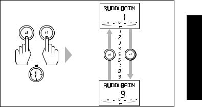
Changing the rudder gain
Decrease |
Increase |
rudder gain |
rudder gain |
SECOND
D5400-1
To make a temporary change to the rudder gain:
1.Press the -1 and +1 keys together for 1 second to display the rudder gain (RUDD GAIN) screen
Note: If you have set up the RUDD GAIN screen as a default data page (see page 104) you can also access it by pressing disp and then scrolling through the data pages.
2.Press -1 or +1 to change the rudder gain.
3.Press disp or wait for 5 seconds to return to the previous display.
Note: See page 96 for instructions on how to check that the rudder gain is set correctly.
Operation Basic 2

2 Basic Operation
14 |
ST4000+ Wheel & Tiller Autopilots: Owner’s Handbook |
2.4Autopilot alarms
Responding to alarms
The ST4000+ activates the alarms listed on the following pages:
•Unless otherwise stated, you should deal with alarms by pressing standby to clear the alarm and return to hand steering.
•In some situations, the autopilot will raise more than one alarm. When you have dealt with the first alarm, the autopilot will display the next alarm.
SeaTalk Failure alarm (STLK FAIL)
The ST4000+ displays the SeaTalk failure message if there is a wiring fault in the SeaTalk connection.
Off Course alarm (OFFCOURSE)
= deviation to port

 = deviation to starboard
D3315-2
The ST4000+ activates this alarm when the boat has been off course from the locked heading by more than the specified angle* for longer than 20seconds. It shows whether the deviation is to port or starboard.
Note: * You can adjust this specified alarm angle in Dealer setup (see page 109).
1.To cancel the off course alarm, press standby to return to hand steering.
2.Check whether your boat is carrying too much sail, or whether the sails are badly balanced. You can usually significantly improve course keeping by improving the sail balance.
Note: The ST4000+ also clears the alarm if the heading recovers, if you change the course, or if you change the operating mode.

Chapter 2: Basic Operation |
15 |
Wind Shift alarm (WINDSHIFT)
The ST4000+ activates the Windshift alarm when it detects a change in the apparent wind angle of more than 15° (see page 29).
Large Cross Track Error alarm (LARGE XTE)
The ST4000+ activates this alarm when the cross track error exceeds 0.3 nm (see page 22).The alarm clears if the heading recovers, if you change the course, or if you change the operating mode.
Drive Stopped alarm (DRIVESTOP)
The ST4000+ activates this alarm if:
•the rudder position sensor fails, or
•the autopilot is unable to turn the rudder (this occurs if the weather load on helm is too high, or if the rudder position sensor has passed beyond the preset rudder limits or rudder end-stops)
Data Not Received alarm (NO DATA)
The ST4000+ activates this alarm in any of the following situations:
•the compass is not connected
•the autopilot is in Wind Vane mode and it has not received wind angle data for 30 seconds
•the autopilot is in Track mode and:
•the boat has arrived at the last waypoint in the track, or
•the autopilot is not receiving SeaTalk navigation data, or
•the position sensor (GPS, Loran, Decca) is receiving a low strength signal – this will clear as soon as the signal strength improves
The autopilot stops adjusting the heading as soon as it loses data.
Waypoint Advance alarm (NEXT WPT?)
The ST4000+ activates the Waypoint Advance alarm whenever the target waypoint number changes. This occurs when:
•you select automatic acquisition by pressing track from Auto
•you request waypoint advance by pressing track for 1 second in Track mode (with SeaTalk navigators only)
Operation Basic 2
Loading...